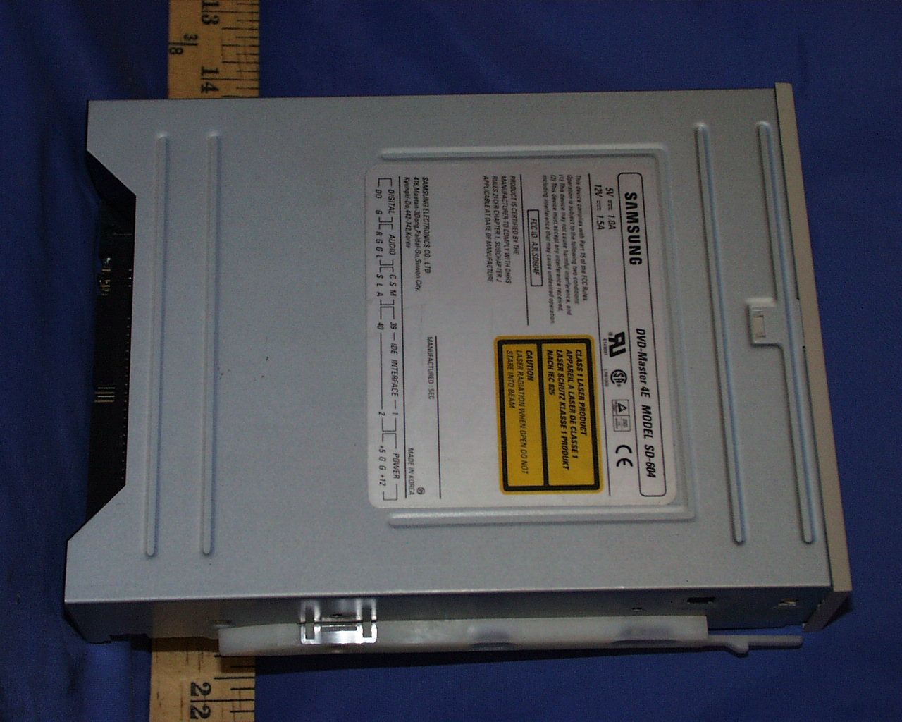
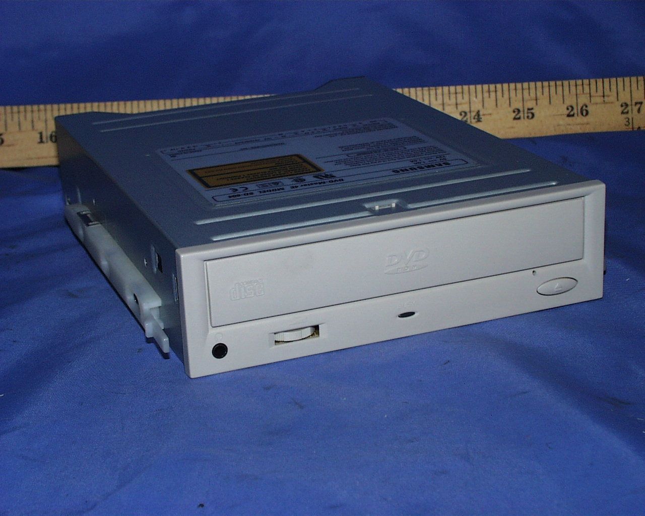
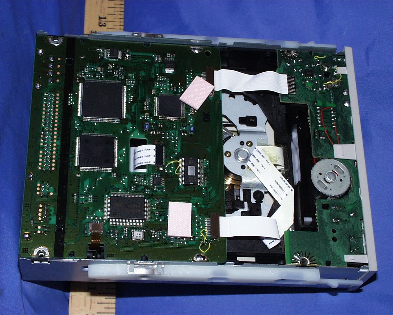
A3LSD604FDVD ROM DRIVE
Samsung Electronics Co Ltd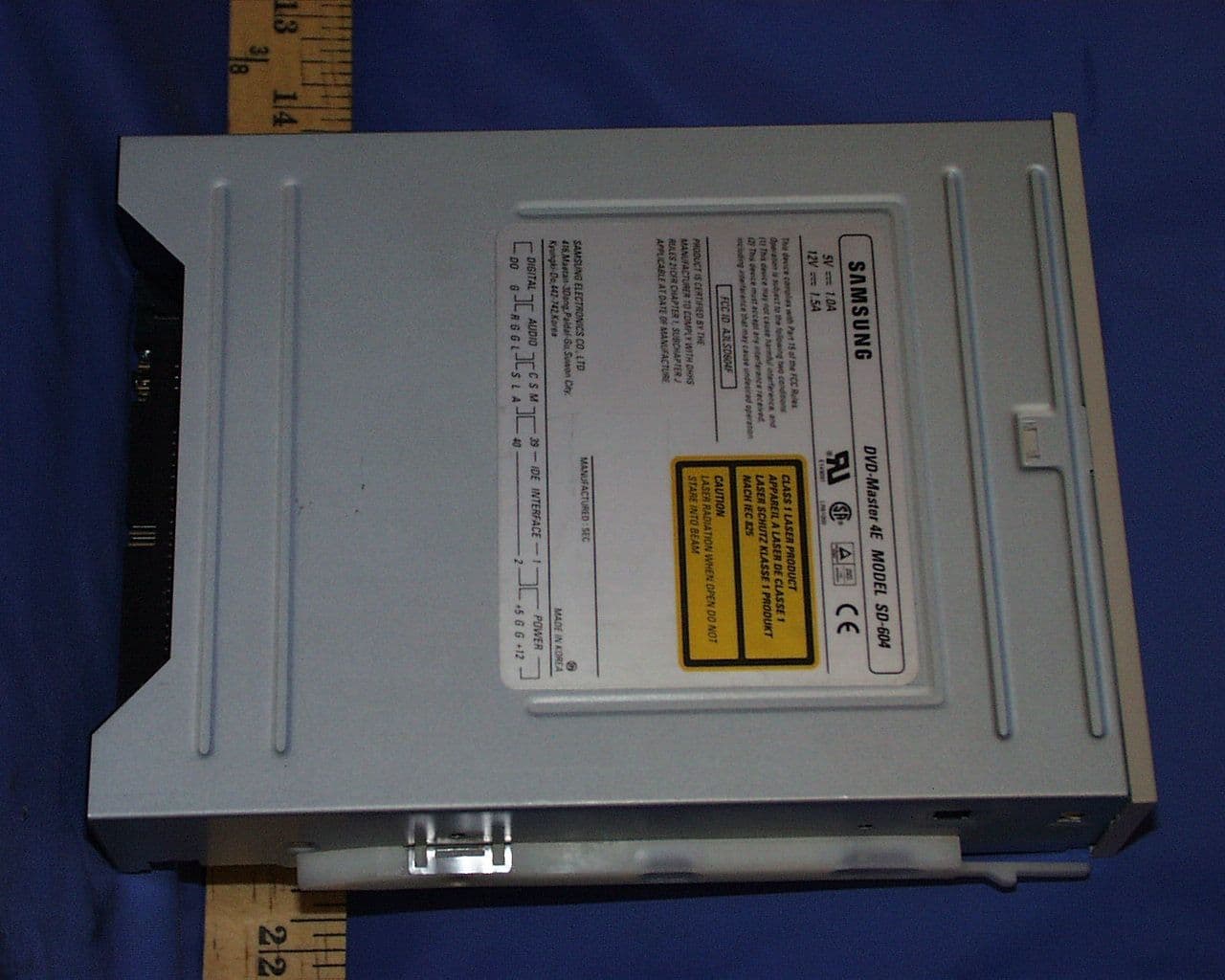
Click to zoom
Application Details
- Equipment Class
- JBP - Part 15 Class B Computing Device Peripheral
- Date of Grant
- Mar 10, 1999
- Application Purpose
- Original Equipment
- Date of Application
- Jan 21, 1999
- Equipment Note
- DVD ROM DRIVE
- Company
- Samsung Electronics Co Ltd
- Country
- United States
Documents & Files
Document Text
Text extracted from the exhibit documents filed with the FCC. Open a document above to read the original.
Users Manual
1 Internal DVD-ROM DRIVE SD-604 User’s Manual English Safety Warnings The following diagrams illustrate the precautions to be taken when using your DVD-ROM drive. You must not use the drive in any manner other than that specified in this guide. CAUTION Do not attempt to repair the DVD-ROM drive yourself. Contact your dealer or local SAMSUNG representative for all repairs. Use of controls or adjustments or performance of procedures other than those specified here in may result in hazardous radiation exposure. WARRANTY Please refer to the Samsung limited warranty statements. To reduce the risk of fire or electric shock, do not expose this appliance to rain or moisture. As SD-604 has a steel ball installed in the turntable for the purpose of reducing the vibration and noises to be generated while the disc shaft rotates, you may hear the ball clicking sounds when the driver is handled manually or when it rotates at a low speed. But it is not a problem. SDR(Eng) 11/12/98 8:11 AM Page 1 2 3 English Front View of the DVD-ROM Drive Rear View of the DVD-ROM Drive COMPACT 1 2 3 4 5 6 1 Headphone Connector The audio output connector enables you to plug stereo headphones into the drive. It requires a 3.6 mm stereo mini-jack. 2 V olume Control Dial This control dial adjusts the volume for your headphones.Y ou can only use the headphone jack and volume control when you have installed the required software utilities. For example, the Microsoft W indows Media player can be used. 3 LED It lights when a DVD/CD disc is loaded or is worked. 4 Disc T ray The disc tray opens and closes automatically when you press the Open/Close button. * When you place a disc in the tray , make sure that the label on the disc is facing upwards. If you are not loading or unloading a disc, the tray should remain closed. 5 Emergency hole If the tray does not open when you press the Open/Close button, insert a small, metal rod (for example, an unwound paper clip) into this hole to eject the disc. * This function should only be performed when the computer is powered OFF . 6 Stop(Open/Close) Button When in play , press the stop key and when in stop, press open/close key . 2 1 3 4 5 1 Digital Output T erminal Connect an audio cable of the board that supports digital output to this terminal. 2 Audio Output Connector Y ou can connect a sound card to your drive using this four-pin connector . â This function is not covered in detail in this guide. Refer to the documentation supplied with your sound card. 3 Device Configuration Jumper Usually , this is a pre-set configuration as illustrated below: * V erify that the setting is as illustrated. If it is not, simply remove the jumper and place it in the correct position. 4 Host IDE Interface Connector This input/output interface connector is used to connect the 40-pin flat cable from the IDE interface to the drive. 5 Power Connector The power connector is a four-conductor male plug. CS SL MA SDR(Eng) 11/12/98 8:11 AM Page 2 4 5 English Before you install the DVD-ROM drive, we strongly recommend that you make certain thatyour set-up meets the system requirements listed below . System RequirementsInstall the drive in your computer horizontally , making sure that the Open/Close button is on the right. Installing the DVD-ROM Drive 1 T urn OFF your computer . Remember to verify the configuration jumper on the rear of the DVD-ROM drive. T o install the drive, pr oceed as follows. 2 Remove the cover of your PC(main unit of the computer). 3 Remove the blank cover panel for the 5.25 inch unit in which the DVD-ROM drive is to be installed. 4 Connect the DVD-ROM drive to the IDE interface and power cables located inside your computer . * Connectors are keyed so it is impossible to put them in an incorrect position. Do not force the connectors, if they do not seem to fit. 5 Install the DVD-ROM drive into the unit and secure it with mounting screws (recommended standard M3x6x4). u Depending on your PC model, you may need to attach guide rails to the drive, so that the drive is held firmly in place.On the ground that the guide rails are parts of the computer , if you don’t have these, please purchase separately . u If you use screws that are longer than the recommended standard, you may damage the drive. 6 Put the cover back on your PC. Item Description T ype of computer Intel Pentium 166MHz, RAM 16MB(or higher) with anIDE interface (or a 100% IBM-compatible computer) Free expansion unit 5.25 inch Disk space 100 MB minimum W indows version 95 OSR2 (or higher) Playback of DVD V ideo PC with W indow95 OSR2 DVD-V ideo playback software and appropriate hardware (MPEG2 card etc.) i For further details, refer to the documentation that comes with DVD-V ideo playback software Installing the SoftwareY ou can install the device driver for DOS or for W indows. 1 T urn on your computer and wait for it to boot. 7 Reboot your system. Result : u The computer restarts u Both the device driver and MSCDEX are loaded. 6 When the Setup Completed screen is displayed, remove the installation floppy disk from the drive. 2 Insert the driver disk into a floppy disk drive (usually the A drive). 4 Run the program: 5 T o... Then enter ... Confirm the installation Y Exit without installing N Result : If you answer Y (Y es), the installation program automatically u Creates a SAMSUNG directory on your hard disk, u Copies the required softwares, u Modifies the CONFIG.SYS and AUT OEXEC.BA T files. 3 If you are a... Then... DOS user u T ype a: at the DOS prompt. u Press the RETURN key . W indows user u Access the File Manager . u Click on the A icon. W indows 95 user u When you are in W indows 95, it is not necessary to install Device Driver . Whereas, when you are in Dos Mode of W indows 95, then install as follows. W indows 95 user u Click on MY COMPUTER icon. W indows 95 user u Click on the A icon. If you are a... Then... DOS user u T ype CDSETUP after the a: prompt. u Press RETURN. W indows user Double-click CDSETUP .EXE from the W…
Text truncated - open the document above for the full version.
Block Diagram
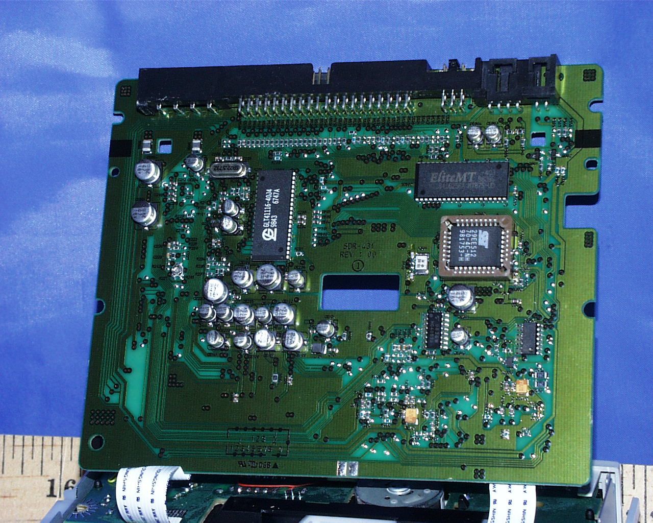
SD-604BLOCKDIAGRAM SPINDLE MOTOR PICK-UP SPINDLE DRIVE BA6849FP ACTURATOR & STEP DRIVE M56788FP LOADINGMOTOR RF-AMP TA1293F SERVO/DSP TC9453F SYSTEM CONTROL KS88C4504 (SAMSUNG) INTERFACE TC9469F (TOSHIBA) HOST INTERFACE (IDE) HEADPHONE FLASHROM 512KB STEPMOTOR 4MDRAM 1MDRAM BH3541F 22.5792MHz 50MHz 18MHz
ID Label/Location Info
PROPOSED FCC ID LABEL LOCATION APPLICANT:SAMSUNG ELECTRONICS CO., LTD. FCC ID:A3LSD604F FCC ID LABEL AREA
Test Report
FCC CFR47 PART 15 DIGITAL DEVICE TEST REPORT FOR DVD ROM DRIVE MODEL : SD-604 FCC ID: A3LSD604F REPORT NUMBER: 98U0117-1 ISSUE DATE: DECEMBER 17, 1998 Prepared for SAMSUNG ELECTRONICS CO., LTD. 416 MAETAN DONG, PALDAL GU SUWON SHI, KOREA Prepared by COMPLIANCE ENGINEERING SERVICES, INC. d.b.a. COMPLIANCE CERTIFICATION SERVICES 1366 BORDEAUX DRIVE SUNNYVALE, CA 94089, USA TEL: (408) 752-8166 FAX: (408) 752-8168 REPORT NO:98U0117-1 FCC ID: A3LSD604F DATE:DECEMBER 17, 1998 EUT: DVD ROM DRIVE COMPLIANCE CONSULTING SERVICESDOCUMENT NO:CCSUP4002C 1366 BORDEAUX DRIVE SUNNYVALE, CA 94089 USA TEL:(408) 752-8166 FAX:(408) 752-8168 This report shall not be reproduced except in full, without the written approval of CCS. TABLE OF CONTENTS PAGE 1. VERIFICATION OF COMPLIANCE ..............................................1 2. PRODUCT DESCRIPTION. ....................................................2 3. TESTED SYSTEM DETAILS ...................................................2 4. TEST FACILITY ...........................................................3 5. ACCREDITATION AND LISTING... ............................................3 6. MEASUREMENT INSTRUMENTATION .............................................3 7. MEASURING INSTRUMENT CALIBRATION ........................................3 8. UNITS OF MEASUREMENT... .................................................4 9. ANTENNAS.................... ............................................4 10. CLASSIFICATION OF DIGITAL DEVICE. .......................................5 11. RADIATED EMISSION LIMITS ................................................5 12. CONDUCTED EMISSION LIMITS ...............................................6 13. CONDUCTED EMISSION TEST PROCEDURE .......................................8 14. RADIATED EMISSION TEST PROCEDURE ........................................8 15. AMBIENT CONDITIONS... ...................................................9 16. SYSTEM TEST CONFIGURATION ...............................................9 17. EQUIPMENT MODIFICATIONS...... ..........................................10 18. EUT SETUP PHOTOS..... ..................................................11 19. TEST EQUIPMENT LIST ....................................................12 20. TEST RESULT SUMMARY ....................................................13 APPENDICES ..................................................................15 .EXTERNAL I/O CABLE CONSTRUCTION DESCRIPTION .CONFIGURATION BLOCK DIAGRAM .EUT PHOTOGRAPHS REPORT NO:98U0117-1 FCC ID: A3LSD604F DATE:DECEMBER 17, 1998 EUT: DVD ROM DRIVE 1 OF 19 COMPLIANCE CERTIFICATION SERVICESDOCUMENT NO:CCSUP4002D 1366 BORDEAUX DRIVE SUNNYVALE, CA 94089 USA TEL:(408) 752-8166 FAX:(408) 752-8168 This report shall not be reproduced except in full, without the written approval of CCS. 1. VERIFICATION OF COMPLIANCE COMPANY NAME: SAMSUNG ELECTRONICS CO., LTD. 416 MAETAN DONG, PALDAL GU SUWON SHI, KOREA CONTACT PERSON: BEN KIM / MANAGER TELEPHONE NO: 408-544-5124 MODEL NO/NAME: SD-604 SERIAL NO: N/A DATE TESTED: DECEMBER 17, 1998 TYPE OF EQUIPMENT: INFORMATION TECHNOLOGY EQUIPMENT (ITE) MEASUREMENT DISTANCE: (X) 3 METER ( ) 10 METER TECHNICAL LIMIT: CLASS B FCC RULES: PART 15 MEASUREMENT PROCEDURE ANSI C63.4:92 EQUIPMENT AUTHORIZATION PROCEDURE CERTIFICATION MODIFICATIONS MADE ON EUT YES NO DEVIATIONS FROM MEASUREMENT PROCEDURE YES (refer to section 20 for comments) NO RADIATED EMISSION TEST RESULT -9.5 dB @ 124.99 MHz/HORIZONTAL CONDUCTED EMISSION TEST RESULT -7.0 dB @ 15.915 MHz/L1 The above equipment was tested by Compliance Certification Services for compliance with the requirements set forth in the FCC CFR 47, PART 15. The results of testing in this report apply to the product/system which was tested only. Other similar equipment will not necessarily produce the same results due to production tolerance and measurement uncertainties. Approved By MIKE C.I. KUO / VICE PRESIDENT COMPLIANCE CERTIFICATION SERVICES REPORT NO:98U0117-1 FCC ID: A3LSD604F DATE:DECEMBER 17, 1998 EUT: DVD ROM DRIVE 2 OF 19 COMPLIANCE CERTIFICATION SERVICESDOCUMENT NO:CCSUP4002D 1366 BORDEAUX DRIVE SUNNYVALE, CA 94089 USA TEL:(408) 752-8166 FAX:(408) 752-8168 This report shall not be reproduced except in full, without the written approval of CCS. 2. PRODUCT DESCRIPTION CHASSIS TYPE METAL LIST OF EACH OSC. OR XTAL. FREQ. (FREQ.>=1 MHz) 20, 20.05, 50 MHz NUMBER OF PCB LAYERS 4 BOARD REVISION NO 02 NO. OF EXTERNAL I/O CONNECTORS 1 X PHONE JACK 3. TESTED SYSTEM DETAILS The Model names for all equipment, plus descriptions of all cables used in the tested system (including inserted cards) are: External Peripheral Devices Device Type ManufacturerModel NumberSerial No.FCC ID / DoC MONITOR SUN MICROSYSTEM CHB7727L N/A DoC KEYBOARD UNISYS ACK-101-KBD N/A EW4KPQ24790 MOUSE MICROSOFT MOUSE 2.0A N/A C3KSMP1 MODEM SMARTEAM 103/212A A038329 EF56A5103/212A PRINTER HP 2225C 2511S41679 BS46XU2225C COMPUTER AST ADVANTAGE 812 445ATB004828 DJKMORRIS-MT-P SPEAKER MLI CP55 N/A N/A REPORT NO:98U0117-1 FCC ID: A3LSD604F DATE:DECEMBER 17, 1998 EUT: DVD ROM DRIVE 3 OF 19 COMPLIANCE CERTIFICATION SERVICESDOCUMENT NO:CCSUP4002D 1366 BORDEAUX DRIVE SUNNYVALE, CA 94089 USA TEL:(408) 752-8166 FAX:(408) 752-8168 This report shall not be reproduced except in full, without the written approval of CCS. 4. TEST FACILITY The open area test sites and conducted measurement facilities used to collect the radiated data are located at 561F Monterey Road, Morgan Hill, California, USA. The sites are constructed in conformance with the requirements of ANSI C63.7, ANSI C63.4 and CISPR Publication 22. 5. ACCREDITATION AND LISTING The test facilities used to perform radiated and conducted emissions tests are accredited by National Voluntary Laboratory Accreditation Program for the specific scope of accreditation under Lab Code:200065-0 to perform Electromagnetic Interference tests according to FCC PART 15 AND CISPR 22 requirements. No part of this report may be used to claim or imply product endorsem…
Text truncated - open the document above for the full version.
Contact Information
Applicant
Jenni Chun(General Manager)
Technical Contact
COMPLIANCE ENGINEERING SERVICES, INC.MIKE KUO
[email protected]408-752-8166
1366 BORDEAUX DRIVE · SUNNYVALE, California · United States
Non-Technical Contact
COMPLIANCE ENGINEERING SERVICES, INC.MIKE KUO
[email protected]408-752-8166
Test Firm
Compliance Certification Services IncSteve Cheng
Technical Specifications
| # | Rule Parts | Frequency Range | Power Output |
|---|---|---|---|
| 1 | 15B | - | - |
Other Applications from Samsung Electronics Co Ltd
A3LSMS741B
Aug 05, 2026Portable Handset
Equipment Class
6VL - 15E 6 GHZ Very Low Power DeviceA3LSMX940
Jul 31, 2026BT,BLE Tablet DTS,UNII a,b,g,n,ac,ax,be and digitizer
Equipment Class
DTS - Digital Transmission SystemA3LSMS741U
Jul 30, 2026Portable Handset
Equipment Class
6CD - 15E 6 GHz Low Power Dual ClientA3LSMX840
Jul 27, 2026BT,BLE Tablet DTS,UNII a,b,g,n,ac,ax and Digitizer
Equipment Class
DSS - Part 15 Spread Spectrum TransmitterA3LSMX848U
Jul 27, 2026WCDMA, LTE, 5G NR Tablet BT,BLE, DTS,UNII a b g n ac ax and Digitizer
Equipment Class
JBP - Part 15 Class B Computing Device Peripheral