A3LSGHM140LCellular/PCS GSM Phone
Samsung Electronics Co Ltd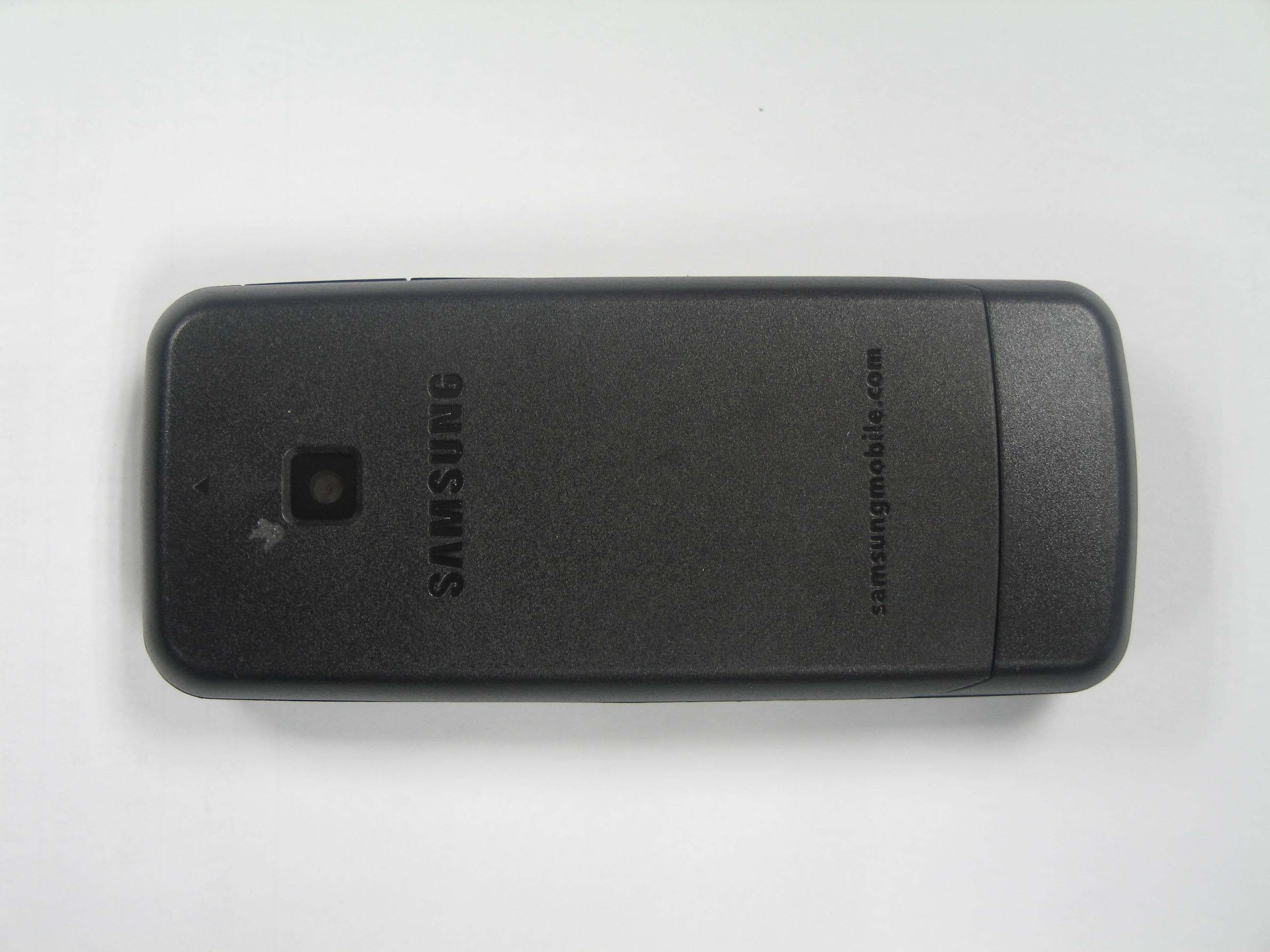
Click to zoom
Application Details
- Equipment Class
- PCE - PCS Licensed Transmitter held to ear
- Date of Grant
- Mar 05, 2008
- Application Purpose
- Original Equipment
- Date of Application
- Mar 05, 2008
- Equipment Note
- Cellular/PCS GSM Phone
- Frequency Range
- 1850.20000000 - 1909.80000000
- Company
- Samsung Electronics Co Ltd
- Country
- United States
Documents & Files
Document Text
Text extracted from the exhibit documents filed with the FCC. Open a document above to read the original.
Users Manual
Printed in Korea Code No.: GH68- xxxxx A English (LTN). 0 1/2008. Rev. 1.0 World Wide Web http://www.samsungmobile.com SGH-M1 4 0L User’s Guide • Depending on the software installed or your service provider or country, some of the descriptions in this guide may not match your phone exactly. • Depending on your country, your phone and accessories may appear different from the illustrations in this guide. Installing the SIM card and battery 1. Remove the battery cover and insert the SIM card. 2. Install the battery and reattach the cover. Battery cover Battery Charging the battery 1. Plug the supplied travel adapter into the phone and a power outlet. 2. When charging is finished, unplug the adapter. Note : Do not remove the battery from the phone without unplugging the adapter first. Otherwise, the phone may be damaged. With the triangle facing the front of your phone Phone layout and key functions Web access/ Confirm key In Idle mode, accesses the web browser. In Menu mode, selects the highlighted option or confirms input. Voicemail server key In Idle mode, accesses your voicemail server when held down. Soft keys Perform functions indicated by the text above the key. 4-way navigation keysIn Idle mode, access your favorite menus directly or adjust the volume level.In Menu mode, scroll through menu options.Power/End keyTurns the phone on or off when held down. Also ends a call.Silent mode key X Silent mode Dial key Makes and answers a call. In Idle mode, retrieves the most recent calls. Cancel/Clear keyDeletes characters from the display. Returns the display to the previous menu level. Sends an SOS message when pressed four times with the key locked.X SOS mode Keypad lock key X Keypad lock mode Alphanumeric keys Display Your phone is in Idle mode when you are not on a call or using a menu. You must be in Idle mode to dial a phone number. Silentmode Press and hold in Idle mode to disable all sounds on the phone. To exit, press and hold this key again. Keypad lock mode Press and hold in Idle mode and then press the Yes soft key to lock the keypad and ignore accidental key pressing. To unlock, press the Unlock soft key and then . SOSmode Press C four times in Idle mode with the key locked to send an SOS message to preset numbers. Once the SOS message is sent, the phone will change to SOS mode and will receive calls only from the registered recipients. Upon receiving a call from the SOS message recipients, th e phone will automatically answer the call. Press to exit SOS mode. Text and graphicsSoft key function indicators Menu Phonebook Icons Your phone displays the following status indicators on the top of the screen: Icon Description Signal strengthCall in progressOut of your service area or Offline mode; you cannot make or receive calls except for emergency callsSOS message feature activeGPRS networkAlarm setSilent modeRinger type•None: Melody•: Vibration• : Vibration then melody Call diverting feature activeNew text messageNew multimedia messageNew voicemail messageBattery power level Switching on or off the phone 1. Press and hold for more than on e second to switch on the phone. 2. If the time & date message appears, press the Yes soft key and set the time and date by following the onscreen instructions. 3. Press and hold for more than tw o seconds to switch off the phone. Changing the display language 1. In Idle mode, press the Menu soft key. 2. Select Phone settings → Language → Text language . 3. Select a language. Making a call 1. In Idle mode, enter an area code and phone number, and press . 2. Press to end the call. Answering a call 1. When the phone rings, press the Accept soft key or to answer a call. Press to reject the call. 2. Press to end the call. Adjusting the volume 1. In Idle mode, press the Menu soft key. 2. Select Sound settings → Incoming calls → Ring volume . 3. Press the Navigation keys to adjust the volume level.4. Press the Save soft key. While a call is in progress, press Up or Down to adjust the earpiece volume. Changing a ringtone for calls 1. In Idle mode, press the Menu soft key. 2. Select Sound settings → Incoming calls → Default ringtones or My sounds . 3. Select a ringtone and press the Yes soft key. Redialing recent numbers 1. In Idle mode, press . 2. Press Up or Down to scroll to the number you want. 3. Press to dial the number. Using the menus In Idle mode, press the Menu soft key to enter the main menu. Use the 4-way navigation keys to scroll up, down, left, or right through the menu system, highlight menu items, change feature settings, and play games. To exit the menu without changing the menu settings, press this key. Labels at the bottom corners of the display show the current soft key functions. Press the left soft key or right soft key to perform the function indicated. To return to the previous menu level, press the Back soft key or C . To select or modify a menu or feature:1. In Idle mode, press the Menu soft key. 2. Press the Navigation keys to reach a desired menu and then press the Select soft key or . 3. If the menu contains any submenus, locate the one you want by pressing the Navigation keys. Press the Select soft key or to enter the submenu.If the selected menu contains additi onal submenus, repeat this step. 4. Press the Navigation keys to find the setting of your choice.5. Press the Select soft key or to confirm your chosen setting. Shortcut numbersYou can quickly access the menu you want by using shortcut numbers. The shortcut number displays in front of the menu name in Menu mode. Menu map 1. Call log1.1 Missed calls1.2 Received calls1.3 Dialled calls1.4 Delete all1.5 Call time1.6 Call costs*2. Network services2.1 Call diverting2.2 Call barring2.3 Call waiting2.4 Network selection2.5 Caller ID2.6 Band selection3. Applications3.1 Voice recorder3.2 SIM-AT*4. Sound settings4.1 Incoming calls4.2 Messages4.3 Power on/off4.4 Connection tone4.5 Keypad tone 4.6 Minute minder 4.7 Silent mode4.8 Alerts on call 5. Messages5.1 Text messages5.2 Mult…
Text truncated - open the document above for the full version.
Cover Letter(s)
SAMSUNG ELECTRONICS AMERICA, INC. American QA Lab 18600 Broadwick St. Rancho Dominguez, CA 90220 Date: March 5, 2008 Federal Communications Commission Authorization and Evaluation Division 7435 Oakland Mills Road, http Columbia, MD 21046 RE: Request of Confidentiality for FCC ID: A3LSGHM140L To Whom It May Concern: Pursuant to Sections 0.457 and 0.459 of the Commission’s Rules (CFR 47), and Section 552 (b) (4) of the Freedom of Information Act, SAMSUNG ELECTRONICS CO.,LTD. hereby requests confidentiality and treatment of certain information accompanying this application. The materials contain trade secrets and proprietary information not customarily released to the public. The public disclosure of these matters might be harmful to the Applicant and provide unjustified benefits to its competitors. We are also hereby request Short-Term Confidentiality for 180 days after the grant as outlined in Public Notice DA 04-1705. This provision will give SAMSUNG ELECTRONICS CO.,LTD. temporary confidentiality of commercially sensitive information prior to product release. The requested Permanent and Short-Term Confidential exhibits are listed as follows: PERMANENT AND SHORT-TERM CONFIDENTIAL LIST Exhibit Description 1 Block Diagram 2 Operational Description 3 Schematics PERMANENT 4 Parts List & Tune-Up Procedure 5 External Photos 6 Internal Photos 7 Test-Setup Photos SHORT-TERM 8 Users Manual The Applicant understands that pursuant to Rule 0.457, disclosure of this application and all accompanying documentations, where applicable, will not be made public before the date of the Grant for this application. Sincerely, Steve Kim General Manager American QA Lab SAMSUNG Electronics America INC.
ID Label/Location Info
박태산 SGH-M140L(LTN) PP + OPP(T=0.08) 한성 080214 080214 IMEI: SGH-M140L A3LSGHM140L -M140LGSMH 600 mA WHITE 박태산 SGH-M140 PP + OPP(T=0.08) 한성 080214 080214 IMEI: SGH-M140 A3LSGHM140 -M140GSMH 600 mA WHITE IMEI: SGH-M140 A3LSGHM140 -M140GSMH 600 mA
RF Exposure Info
of 32 SAMSUNG ELECTRONICS Co., Ltd., Regulatory Compliance Group IT R&D Center 416, Maetan-3dong, Yeongtong-gu, Suwon-si, Gyeonggi-do, Korea 443-742 TEST REPORT ON SAR Model Tested: SGH-M140L Additional Model: SGH-M140 FCC ID (Requested): A3LSGHM140L Job No: FF-029 Report No: FF-029-S1 Date issued: Mar.04, 2008 - Abstract – This document reports on SAR Tests carried out in accordance with FCC/OET Bulletin 65, Supplement C(July 2001). Prepared By YB KIM - Test Engineer Authorized By JH NAM - Technical Manager Report Number: FF-029-S1 2 of 32 Contents 1. GENERAL INFORMATION............................................................................................................. 3 2. DESCRIPTION OF DEVICE ........................................................................................................... 3 3. DESCRIPTION OF TEST EQUIPMENT ......................................................................................... 4 3.1 SAR Measurement Setup ......................................................................................................4 3.2 E-field Probe .......................................................................................................................... 6 3.3 SAM Phantom ........................................................................................................................ 8 3.4 Brain & Muscle Simulating Mixture Characterization ............................................................. 8 3.5 Device Holder for Transmitters ..............................................................................................9 3.6 Validation Dipole .................................................................................................................... 9 3.7 Equipment Calibration.......................................................................................................... 10 4. SAR MEASUREMENT PROCEDURE ......................................................................................... 11 5. DESCRIPTION OF TEST POSITION ........................................................................................... 12 5.1 SAM Phantom Shape...........................................................................................................12 5.2 Cheek/Touch Position .......................................................................................................... 12 5.3 EAR/Tilt 15° Position ............................................................................................................ 14 5.4 Body Holster/Belt Clip Configurations.................................................................................. 15 6. MEASUREMENT UNCERTAINTY................................................................................................ 17 7. SYSTEM VERIFICATION ............................................................................................................. 19 7.1 Tissue Verification ................................................................................................................ 19 7.2 Test System Validation ......................................................................................................... 19 8. SAR MEASUREMENT RESULTS ................................................................................................ 20 8.1 Measurement Results(GSM850 Right Head SAR - Touch) ................................................. 21 8.2 Measurement Results(GSM850 Right Head SAR - Tilt) ...................................................... 22 8.3 Measurement Results(GSM850 Left Head SAR - Touch).................................................... 23 8.4 Measurement Results(GSM850 Left Head SAR - Tilt)......................................................... 24 8.5 Measurement Results(GPRS850 Body SAR without Holster) ............................................. 25 8.6 Measurement Results(GSM1900 Right Head SAR - Touch) ............................................... 26 8.7 Measurement Results(GSM1900 Right Head SAR - Tilt) .................................................... 27 8.8 Measurement Results(GSM1900 Left Head SAR - Touch).................................................. 28 8.9 Measurement Results(GSM1900 Left Head SAR - Tilt)....................................................... 29 8.10 Measurement Results(GPRS1900 Body SAR without Holster)......................................... 30 9. CONCLUSION .............................................................................................................................. 31 10. REFERENCES ............................................................................................................................ 32 Report Number: FF-029-S1 3 of 32 1. GENERAL INFORMATION Test Sample : Dual-Band GSM850/1900 Phone Model Number : SGH-M140L Serial Number : Identical prototype (S/N : # FF-029-C) Manufacturer : SAMSUNG ELECTRONICS Co., Ltd. Contact : DK LEE Phone : +82-31-301-7450 Fax : +82-31-279-7621 Test Standard : §2.1093; FCC/OET Bulletin 65, Supplement C(July 2001) FCC Classification : Licensed Portable Transmitter Held to Ear (PCE) Test Dates : Feb.21, 2008 ~ Feb.22, 2008 Tested for : FCC/TCB Certification 2. DESCRIPTION OF DEVICE Tx Freq. Range : 824.2 ~ 848.8 MHz (GSM850) 1850.20 ~ 1909.80 MHz (GSM1900) Rx Freq. Range : 869.2 ~ 893.8 MHz (GSM850) 1930.20 ~ 1989.80 MHz (GSM1900) Antenna Manufacturer : Partron Model No.: SGH-M140L Antenna Dimensions : 39.4mm × 10.7mm GPRS Class 10 Report Number: FF-029-S1 4 of 32 3. DESCRIPTION OF TEST EQUIPMENT 3.1 SAR Measurement Setup Robotic System Measurements are performed using the DASY4(or DASY5) automated dosimetric assessment system. Which is made by Schmid & Partner Engineering AG (SPEAG) in Zurich, Switzerland and consists of high precision robotics system (Stäubli), robot controller, measurement server, Samsung computer, near-field probe, probe alignment sensor, and the SAM twin phantom containing the brain equivalent material. The r…
Text truncated - open the document above for the full version.
Test Report
SAMSUNG ELECTRONICS Co., Ltd., Regulatory Compliance Group IT R&D Center 416 Maetan3-Dong, Yeongtong-gu, Suwon city, Gyeonggi-Do, Korea 443-742 FCC CFR47 PART 22 & 24 SUBPART CERTIFICATION REPORT Model Tested : SGH-M140L Additional Model : SGH-M140 FCC ID(Requested) : A3LSGHM140L Report No : FF-029-R1 Job No : FF-029 Date issued : March 03 , 2008 - Abstract - All measurement reported herein accordance with FCC Rules, 47CFR Part2, Part22, Part24. Prepared By JH WOO – Test Engineer Authorized By WW JANG - Technical Manager Report Number : FF-029-R1 TABLE OF CONTENT MEASUREMENT REPORT Page 1. FCC CERTIFICATION INFORMATION .....................................................................3 1.1. §2.1033 General Information .........................................................................3 2. INTRODUCTION .......................................................................................................4 2.1. General..........................................................................................................4 3. MEASURING INSTRUMENT CALIBRATION ...........................................................4 4. TEST EQUIPMENT LIST...........................................................................................4 5. DESCRIPTION OF TESTS ........................................................................................4 5.1. Effective Radiated Power / Equivalent Isotropic Radiated Power ..................4 5.2. Radiated Spurious & Harmonic Emission ......................................................4 5.3. Occupied Bandwidth ......................................................................................4 5.4. Spurious and Harmonic Emission at Antenna Terminal..................................4 5.4.1. Occupied Bandwidth Emission Limits ................................................4 5.4.2. Conducted Spurious Emission ...........................................................4 5.5. Frequency Stability / Temperature Variation ...................................................4 6. TEST DATA ...............................................................................................................4 6.1. Effective Radiated Power (E.R.P.)..................................................................4 6.2. Equivalent Isotropic Radiated Power (E.I.R.P.) ..............................................4 6.3. GSM850 Radiated Spurious & Harmonic measurement ................................4 6.4. GSM1900 Radiated Spurious & Harmonic measurement ..............................4 6.5. GSM850 Radiated Spurious & Harmonic Conversion Table ..........................4 6.6. GSM1900 Radiated Spurious & Harmonic Conversion Table ........................4 6.7. Frequency Stability.........................................................................................4 6.7.1. GSM850 Frequency Stability Table ....................................................4 6.7.2. GSM850 Frequency Stability Graph...................................................4 6.7.3. GSM1900 Frequency Stability Table ..................................................4 6.7.4. GSM1900 Frequency Stability Graph.................................................4 7. CONCLUSION...........................................................................................................4 8. TEST PLOTS.............................................................................................................4 Report Number : FF-029-R1 MEASUREMENT REPORT 1. FCC Certification Information The following information is in accordance with FCC Rules, 47CFR Part2, Subpart J, Sections 2.1033 – 2.1055. 1.1. §2.1033 General Information • Applicant Name : SAMSUNG ELECRONICS CO., LTD. • Address : 416 Maetan3-Dong, Yeongtong-gu, Suwon City Gyeonggi-Do, Korea 443-742 • Attention : SungJoo KIM, Engineering Manager (QA Lab) • FCC ID : A3LSGHM140L • Additional Model : SGH-M140 • Quantity : Quantity production is planned • Emission Designators : 251KGXW(GSM850) 247KGXW(GSM1900) • Tx Freq. Range : 824.2 - 848.8MHz (GSM850) 1850.2MHz - 1909.8MHz (GSM1900) • Rx Freq. Range : 869.2 - 893.8 MHz (GSM850) 1930.2MHz - 1989.8MHz (GSM1900) • Max. Power Rating : 0.998 W ERP GSM850 (29.99dBm) 0.910 W EIRP GSM1900 (29.59dBm) • FCC Classification(s) : Licensed Portable Tx Held to Ear (PCE) • Equipment (EUT) Type : Dual-Band GSM850/1900 Phone • Frequency Tolerance : ±0.00025% (2.5ppm) • FCC Rule Part(s) : §24(E), §22(H), §2. • Dates of Test : February 19-20, 2008 • Place of Test : SAMSUNG Lab, • Test Report S/N : FF-029-R1 Report Number : FF-029-R1 2. INTRODUCTION 2.1. General These measurement test were conducted at SAMSUNG ELECTRONICS CO., LTD(SUWON). The site address is 416 Maetan3-Dong, Yeongtong-gu, Suwon City, Gyeonggi-Do, Korea 443-742 The site have 1 Fully-anechoic chamber and measurement facility. Measurement Procedure The radiated and spurious measurements were made Fully-anechoic chamber at a 3-meter test range (see Figure2). The equipment under testing was placed on the rotating device at the same height and at a distance of 3-meters from the receive antenna. The rotating device which can rotate horizontal axis was mounted on the turn unit to facilitate rotation around a vertical axis. The measurement was made for each horizontal/vertical position combination with receive antenna horizontally polarized. This measurement was repeated with receive antenna vertically polarized. The substitution antenna will replace the EUT antenna it the same position and in vertical polarization. The frequency of the signal generator shall be set to the frequencies that were measured on the EUT. The signal generator, output level, shall be adjusted until an equal or a known related level to what was measured from the EUT is obtained in the spectrum analyzer. This level was recorded. For readings above 1 GHz, the above procedure is repeated using horn antennas and the difference between the gain of the horn and an isotropic antenna are taken…
Text truncated - open the document above for the full version.
Test Setup Photos
© 2008 SAMSUNG ELECTRONICS Co., Ltd. SAMSUNG FCC ID: A3LSGHM140L Dual-Band GSM 850/1900 Phone
Test Setup Photos
© 2008 SAMSUNG ELECTRONICS Co., Ltd SAMSUNG FCC ID:A3LSGHM140L Dual-Band GSM850/1900 Phone © 2008 SAMSUNG ELECTRONICS Co., Ltd SAMSUNG FCC ID:A3LSGHM140L Dual-Band GSM850/1900 Phone © 2008 SAMSUNG ELECTRONICS Co., Ltd SAMSUNG FCC ID:A3LSGHM140L Dual-Band GSM850/1900 Phone 1.5Cm © 2008 SAMSUNG ELECTRONICS Co., Ltd SAMSUNG FCC ID:A3LSGHM140L Dual-Band GSM850/1900 Phone © 2008 SAMSUNG ELECTRONICS Co., Ltd SAMSUNG FCC ID:A3LSGHM140L Dual-Band GSM850/1900 Phone © 2008 SAMSUNG ELECTRONICS Co., Ltd SAMSUNG FCC ID:A3LSGHM140L Dual-Band GSM850/1900 Phone © 2008 SAMSUNG ELECTRONICS Co., Ltd SAMSUNG FCC ID:A3LSGHM140L Dual-Band GSM850/1900 Phone © 2008 SAMSUNG ELECTRONICS Co., Ltd SAMSUNG FCC ID:A3LSGHM140L Dual-Band GSM850/1900 Phone © 2008 SAMSUNG ELECTRONICS Co., Ltd SAMSUNG FCC ID:A3LSGHM140L Dual-Band GSM850/1900 Phone © 2008 SAMSUNG ELECTRONICS Co., Ltd SAMSUNG FCC ID:A3LSGHM140L Dual-Band GSM850/1900 Phone © 2008 SAMSUNG ELECTRONICS Co., Ltd SAMSUNG FCC ID:A3LSGHM140L Dual-Band GSM850/1900 Phone © 2008 SAMSUNG ELECTRONICS Co., Ltd SAMSUNG FCC ID:A3LSGHM140L Dual-Band GSM850/1900 Phone
Contact Information
Applicant
Jenni Chun(General Manager)
Technical Contact
PCTEST Engineering Lab., Inc.Randy Ortanez
[email protected]410-290-6652
6660-B Dobbin Road · Columbia, Maryland · United States
Test Firm
Samsung Electronics Co., Ltd. Global CS CenterPark No cheon
Technical Specifications
| # | Rule Parts | Frequency Range | Power Output | Emission | Tolerance |
|---|---|---|---|---|---|
| 2 | 24E | 1.85 GHz - 1.91 GHz | 910.00 mW | 247KGXW | 2.5 ppm |
Other Applications from Samsung Electronics Co Ltd
A3LSMS741B
Aug 05, 2026Portable Handset
Equipment Class
6VL - 15E 6 GHZ Very Low Power DeviceA3LSMX940
Jul 31, 2026BT,BLE Tablet DTS,UNII a,b,g,n,ac,ax,be and digitizer
Equipment Class
DTS - Digital Transmission SystemA3LSMS741U
Jul 30, 2026Portable Handset
Equipment Class
6CD - 15E 6 GHz Low Power Dual ClientA3LSMX840
Jul 27, 2026BT,BLE Tablet DTS,UNII a,b,g,n,ac,ax and Digitizer
Equipment Class
DSS - Part 15 Spread Spectrum TransmitterA3LSMX848U
Jul 27, 2026WCDMA, LTE, 5G NR Tablet BT,BLE, DTS,UNII a b g n ac ax and Digitizer
Equipment Class
JBP - Part 15 Class B Computing Device Peripheral