A3LSHWA350KPCS GSM Phone with Bluetooth
Samsung Electronics Co Ltd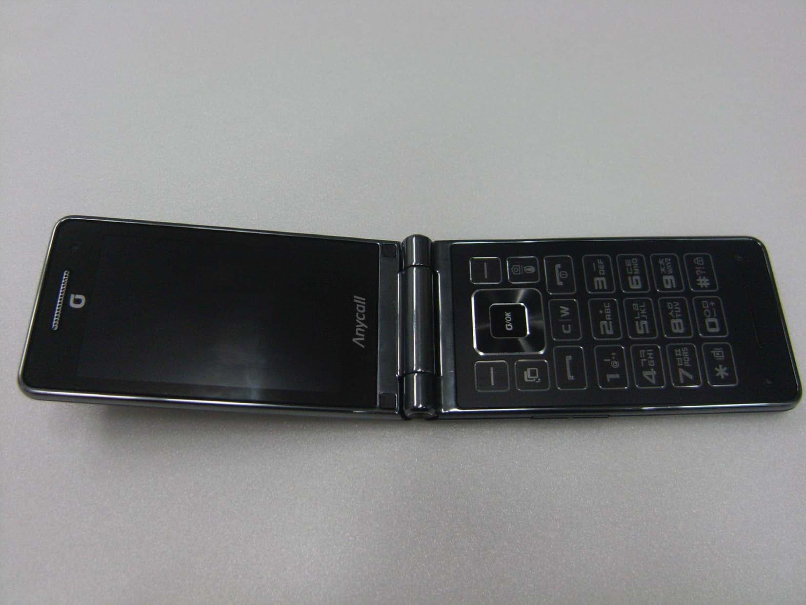
Click to zoom
Application Details
- Equipment Class
- PCE - PCS Licensed Transmitter held to ear
- Date of Grant
- May 08, 2012
- Application Purpose
- Original Equipment
- Date of Application
- May 07, 2012
- Equipment Note
- PCS GSM Phone with Bluetooth
- Frequency Range
- 1850.20000000 - 1909.80000000
- Company
- Samsung Electronics Co Ltd
- Country
- United States
Documents & Files
Document Text
Text extracted from the exhibit documents filed with the FCC. Open a document above to read the original.
Users Manual
User manual SHW-A350K using this manual Draft 6 2011-12-23 Only for Marketing This user manual has been specially designed to guide you through the functions and features of your mobile phone. To get started quickly, refer to “introducing your mobile phone, Instructional icons Before you start, familiarise yourself with the icons you will see in this manual: Warning—situations that could cause injury to yourself or others Caution—situations that could cause damage to your phone or other equipment Note—notes, usage tips, or additional information Refer to—pages with related information; for example: p. 12 (represents “see page 12”) Õ Followed by—the order of options or menus you must select to perform a step; for example: In Menu mode, select Messages Õ Create new message (represents Messages, followed by Create new message) [ ] Square brackets—phone keys; for example: [](represents the Power/ Menu exit key) < > Angled brackets—softkeys that control different functions at each screen; for example: <OK> (represents the OK softkey) Copyright information Rights to all technologies and products that comprise this device are the property of their respective owners: Bluetooth ® is a registered trademark of the Bluetooth SIG, Inc. worldwide Java™ is a trademark of Sun Microsystems, Inc. Windows Media Player ® is a registered trademark of Microsoft Corporation. contents safety and usage information Safety warnings Safety precautions Important usage information introducing your mobile phone Unpack .. Phone layout Keys Display Icons assembling and preparing your mobile phone Install the SIM card and battery Charge the battery using basic functions Turn your phone on and off Access menus Customise your phone Use basic call functions Send and view messages Add and find contacts troubleshooting safety and usage information Comply with the following precautions to avoid dangerous or illegal situations and ensure peak performance of your mobile phone. Safety warnings Keep your phone away from small children and pets Keep your phone and all accessories out of the reach of small children or animals. Small parts may cause choking or serious injury if swallowed. Protect your hearing Excessive exposure to sound at high volumes can cause hearing damage. Always turn the volume down before plugging the earphones into an audio source and use only the minimum volume setting necessary to hear your conversation or music. Install mobile phones and equipment with caution Ensure that any mobile phones or related equipment installed in your vehicle are securely mounted. Avoid placing your phone and accessories near or in an air bag deployment area. Improperly installed wireless equipment can cause serious injury when air bags inflate rapidly. Handle and dispose of batteries and chargers with care Use only Samsung-approved batteries and chargers specifically designed for your phone. Incompatible batteries and chargers can cause serious injuries or damage to your phone. Never dispose of batteries or phones in a fire. Follow all local regulations when disposing used batteries or phones. Never place batteries or phones on or in heating devices, such as microwave ovens, stoves, or radiators. Batteries may explode when overheated. Never crush or puncture the battery. Avoid exposing the battery to high external pressure, which can lead to an internal short circuit and overheating. Avoid interference with pacemakers Maintain a minimum of 15 cm (6 inches) between mobile phones and pacemakers to avoid potential interference, as recommended by manufacturers and the independent research group, Wireless Technology Research. If you have any reason to suspect that your phone is interfering with a pacemaker or other medical device, turn off the phone immediately and contact the manufacturer of the pacemaker or medical device for guidance. Turn off the phone in potentially explosive environments Do not use your phone at refuelling points (service stations) or near fuels or chemicals. Turn off your phone whenever directed by warning signs or instructions. Your phone could cause explosions or fire in and around fuel or chemical storage and transfer areas or blasting areas. Do not store or carry flammable liquids, gases, or explosive materials in the same compartment as the phone, its parts, or accessories. Reduce the risk of repetitive motion injuries When sending text messages or playing games on your phone, hold the phone with a relaxed grip, press the keys lightly, use special features that reduce the number of keys you have to press (such as templates and predictive text), and take frequent breaks. Safety precautions Drive safely at all times Avoid using your phone while driving and obey all regulations that restrict the use of mobile phones while driving. Use hands-free accessories to increase your safety when possible. Follow all safety warnings and regulations Comply with any regulations that restrict the use of a mobile phone in a certain area. Use only Samsung-approved accessories Using incompatible accessories may damage your phone or cause injury. Turn off the phone near medical equipment Your phone can interfere with medical equipment in hospitals or health care facilities. Follow all regulations, posted warnings, and directions from medical personnel. Turn off the phone or disable the wireless functions when in an aircraft Your phone can cause interference with aircraft equipment. Follow all airline regulations and turn off your phone or switch to a mode that disables the wireless functions when directed by airline personnel. Protect batteries and chargers from damage Avoid exposing batteries to very cold or very hot temperatures (below 0° C/32° F or above 45° C/ 113° F). Extreme temperatures can reduce the charging capacity and life of your batteries. Prevent batteries from contacting metal objects, as this can create a connection between the + and - terminals of your batteries and lead to temporary or per…
Text truncated - open the document above for the full version.
Cover Letter(s)
April 26, 2012 Federal Communications Commission 7435 Oakland Mills Road Columbia MD 21046 Subject: Request for Confidentiality FCC ID: A3LSHWA350K To Whom It May Concern: Pursuant to the provisions of Sections 0.457 and 0.459 of the Commission’s rules (47 CFR §§ 0.457, 0.459), we are requesting the Commission to withhold the following attachments as confidential document from public disclosure indefinitely. Schematics Block Diagram Operational Description Antenna Specification Parts List Tune-Up Procedure Above mentioned document contains detailed system and equipment description are considered as proprietary information in operation of the equipment. The public disclosure of above documents might be harmful to our company and would give competitor an unfair advantage in the market. In additional to above mentioned documents, pursuant to Public Notice DA 04-1705 of the Commission’s policy, in order to comply with the marketing regulations in 47 CFR §2.803 and the importation rules in 47 CFR §2.1204, while ensuring that business sensitive information remains confidential until the actual marketing of newly authorized devices. We are requesting the commission to grant short-term confidentiality request on the following attachments until 180 days External Photos Internal Photos Test Setup Photos User Manual It is our understanding that all measurement test reports, FCC ID label format and correspondence during certification review process cannot be granted as confidential documents and such information will be available for public review once the grant of equipment authorization is issued. Best Regards Sang Kyung (Peter), Ra/ General Manager Samsung Electronics CO. LTD TEL: 310-900-5250 FAX: 310-537-5500 E-mail: [email protected]
Cover Letter(s)
416, Maetan-3 Dong , Yeongtong-Gu, Suwon-City, Gyeonggi-Do 443-742 South Korea Date: 04/09/2012 Compliance Certification Services Certification Division 47173 Benicia Street Fremont, CA 94538, USA To whom it may concern: I, the undersigned, hereby authorize Ms. Claire Hoque/Application Examiner of Compliance Engineering Services, Inc., d.b.a. Compliance Certification Services and hereafter referred to as CCS, to act on our behalf in all manners relating to application for equipment authorization, including signing of all documents relating to these matters. Any and all acts carried out by Ms. Claire Hoque of CCS on our behalf shall have the same effect as acts of our own. I, the undersigned, hereby certify that we are not subject to a denial of federal benefits, that includes FCC benefits, pursuant to Section 5301 of the Anti-Drug Abuse Act of 1988, 21 U.S.C. 853(a). In authorizing CCS as our agent, we still recognize that we are responsible to: a) comply with the relevant provisions of the certification program; b) make all necessary arrangements for the conduct of the evaluation, including provision for examining documentation and access to all areas, records (including internal audit reports) and personnel for the purposes of evaluation (e.g. testing, inspection, assessment, surveillance, reassessment) and resolution of complaints; c) make claims regarding certification only in respect of the scope for which certification has been granted; d) do not use our product certification in such a manner as to bring the Certification Division into disrepute and not make any statement regarding our product certification which the Certification Division may consider misleading or unauthorized; e) upon suspension or cancellation of certification, discontinue use of all advertising matter that contains any reference thereto and return any certification documents as required by the Certification Division; f) use certification only to indicate the products are certified as being in conformity with specified standards; g) endeavor to ensure that no certificate or report nor any part thereof is used in a misleading manner; h) ensure that any reference to our product certification in communication media such as documents, brochures or advertising, complies with the requirements of the Certification Division; i) keep a record of all complaints made known to the us relating to the product’s compliance with requirements of the relevant standard and to make these records available to the Certification Division when requested; j) take appropriate action with respect to such complaints and any deficiencies found in products or services that affect compliance with the requirements for certification; k) document the actions taken. This authorization is valid until further written notice from the applicant. Sincerely Yours, NAME: Sang Kyung(Peter), Ra TITLE: Head of QA Lab (General Manager) Applicant: Samsung Electronics America, Inc Address: 19 Chapin Rd, Building D. Pine Brook, NJ 07058
ID Label/Location Info
and Location Samsung Phone Model: SHW-A350K FCC ID: A3LSHWA350K Label: Location: Top → Back plate of device → Bottom → Phone: Label is placed inside of the battery compartment.
RF Exposure Info
Test report No. : 32IE0169-HO-C-R1 Page : 1 of 69 FCC ID : A3LSHWA350K Issued date : April 20, 2012 Revised date : May 8, 2012 UL Japan, Inc. Head Office EMC Lab. 4383-326 Asama-cho, Ise-shi, Mie-ken 516-0021 JAPAN Telephone: +81 596 24 8116 Facsimile: +81 596 24 8124 13-EM-F0429 SAR TEST REPORT Test Report No. : 32IE0169-HO-C-R1 Applicant :SAMSUNG ELECTRONICS CO., LTD. Type of Equipment :GSM/GPRS1900 Phone with bluetooth Model No. :SHW-A350K FCC ID :A3LSHWA350K Test regulation :FCC47CFR 2.1093 FCC OET Bulletin 65, Supplement C (Edition 01-01) Test Result :Complied FCC Part 24E Head : 0.097W/kg Body : 0.871W/kg 1. This test report shall not be reproduced in full or partial, without the written approval of UL Japan, Inc. 2. The results in this report apply only to the sample tested. 3. This sample tested is in compliance with the limits of the above regulation. 4. The test results in this report are traceable to the national or international standards. 5. This test report must not be used by the customer to claim product certification, approval, or endorsement by NVLAP, NIST, or any agency of the Federal Government. 6 This report is a revised version of 32IE0169-HO-C. 32IE0169-HO-C is replaced with this report. Date of test: April 18, 2012 Representative test engineer: Hisayoshi Sato Engineer of WiSE Japan, UL Verification Service Approved by : Takahiro Hatakeda Leader of WiSE Japan UL Verification Service NVLAP LAB CODE: 200572-0 This laboratory is accredited by the NVLAP LAB CODE 200572-0, U.S.A. The tests reported herein have been performed in accordance with its terms of accreditation. *As for the range of Accreditation in NVLAP, you may refer to the WEB address, http://www.ul.com/japan/jpn/pages/services/emc/about/ma rk1/index.jsp#nvlap Test report No. : 32IE0169-HO-C-R1 Page : 2 of 69 FCC ID : A3LSHWA350K Issued date : April 20, 2012 Revised date : May 8, 2012 UL Japan, Inc. Head Office EMC Lab. 4383-326 Asama-cho, Ise-shi, Mie-ken 516-0021 JAPAN Telephone: +81 596 24 8116 Facsimile: +81 596 24 8124 SECTION 1: Customer information .............................................................................................................................................................. 3 SECTION 2: Equipment under test (E.U.T.) ................................................................................................................................................ 3 2.1 Identification of E.U.T. ....................................................................................................................................... 3 2.2 Product description ............................................................................................................................................. 4 SECTION 3 : Test standard information ...................................................................................................................................................... 5 3.1 Test Specification ............................................................................................................................................... 5 3.2 Procedure ............................................................................................................................................................ 5 3.3 Exposure limit..................................................................................................................................................... 6 3.4 Test Location ...................................................................................................................................................... 6 SECTION 4 : Test result ................................................................................................................................................................................. 7 4.1 Stand-alone SAR result....................................................................................................................................... 7 4.2 Simultaneous transmission SAR result ............................................................................................................... 7 SECTION 5 : Description of the operating mode ......................................................................................................................................... 8 5.1 SAR testing operating modes.............................................................................................................................. 8 5.2 Output power operating modes ........................................................................................................................... 8 5.3 WWAN Output power measurement results ....................................................................................................... 9 5.4 Confirmation before SAR testing ....................................................................................................................... 10 5.5 Confirmation after SAR testing .......................................................................................................................... 10 SECTION6 : Description of the Head/Body setup........................................................................................................................................ 11 6.1 Test position for Head setup ............................................................................................................................... 11 6.2 Description of the Body-worn setup ................................................................................................................... 13 SECTION 7 : Test surrounding ..................................................................................................................................................................... 14 7.1 Measurement uncertainty .................................................................................................................................... 14 SECTI…
Text truncated - open the document above for the full version.
RF Exposure Info
Test report No. : 32IE0169-HO-C-R1 Page : 18 of 69 FCC ID : A3LSHWA350K Issued date : April 20, 2012 Revised date : May 8, 2012 UL Japan, Inc. Head Office EMC Lab. 4383-326 Asama-cho, Ise-shi, Mie-ken 516-0021 JAPAN Telephone: +81 596 24 8116 Facsimile: +81 596 24 8124 APPENDIX 1 : SAR Measurement data 1. Evaluation procedure The evaluation was performed with the following procedure: Step 1: Measurement of the E-field at a fixed location above the ear point or central position of flat phantom was used as a reference value for assessing the power drop. Step 2: The SAR distribution at the exposed side of head or body position was measured at a distance of each device from the inner surface of the shell. The area covered the entire dimension of the antenna of EUT and the horizontal grid spacing was 15 mm x 15 mm (or 10mm x 10mm for 5GHz band). Based on these data, the area of the maximum absorption was determined by spline interpolation. Step 3: Around this point found in the Step 2 (area scan) , a volume of 30mm x 30mm x 30mm or more was assessed by measuring 7 x 7 x 7 points at least, and a volume of 28mm x 28mm x 22.5mm or more was assessed by measuring 8 x 8 x 10 points at least for 5GHz band. And for any secondary peaks found in the Step2 which are within 2dB of maximum peak and not with this Step3 (Zoom scan) is repeated. On the basis of this data set, the spatial peak SAR value was evaluated under the following procedure: (1). The data at the surface were extrapolated, since the center of the dipoles is 1mm(EX3DV3) away from the tip of the probe and the distance between the surface and the lowest measuring point is 1.3 mm. The extrapolation was based on a least square algorithm [4]. A polynomial of the fourth order was calculated through the points in z-axes. This polynomial was then used to evaluate the points between the surface and the probe tip. (2). The maximum interpolated value was searched with a straightforward algorithm. Around this maximum the SAR values averaged over the spatial volumes (1 g or 10 g) were computed by the 3D-Spline interpolation algorithm. The 3D-Spline is composed of three one-dimensional splines with the “Not a knot"-condition (in x, y and z-directions) [4], [5]. The volume was integrated with the trapezoidal-algorithm. One thousand points (10 x 10 x 10) were interpolated to calculate the average. (3). All neighboring volumes were evaluated until no neighboring volume with a higher average value was found. Step 4: Re-measurement of the E-field at the same location as in Step 1. Test report No. : 32IE0169-HO-C-R1 Page : 19 of 69 FCC ID : A3LSHWA350K Issued date : April 20, 2012 Revised date : May 8, 2012 UL Japan, Inc. Head Office EMC Lab. 4383-326 Asama-cho, Ise-shi, Mie-ken 516-0021 JAPAN Telephone: +81 596 24 8116 Facsimile: +81 596 24 8124 2. Measurement data i) PCS1900 Head SHW-A350K PCS1900(GSM) Left Cheek 1850.2MHz Area Scan Communication System: PCS1900; Communication System Band: PCS1900; Frequency: 1850.2 MHz;Duty Cycle: 1:8.30042 Medium parameters used (interpolated): f = 1850.2 MHz; σ = 1.412 mho/m; εr = 38.073; ρ = 1000 kg/m 3 Phantom section: Left Section Measurement Standard: DASY5 (IEEE/IEC/ANSI C63.19-2007) DASY5 Configuration Probe: EX3DV4 - SN3825; ConvF(8.43, 8.43, 8.43); Calibrated: 2011/12/16 Sensor-Surface: 2mm (Mechanical Surface Detection) Electronics: DAE4 Sn509; Calibrated: 2011/07/20 Phantom: SAM with CRP; Type: SAM; Measurement SW: DASY52, Version 52.8 (0); Area Scan (61x101x1): Measurement grid: dx=15mm, dy=15mm Info: Interpolated medium parameters used for SAR evaluation. Maximum value of SAR (interpolated) = 0.195 mW/g Date: 2012/04/17 Ambient Temp. : 24.0 degree.C. Liquid Temp.; 23.5 degree.C. Test report No. : 32IE0169-HO-C-R1 Page : 20 of 69 FCC ID : A3LSHWA350K Issued date : April 20, 2012 Revised date : May 8, 2012 UL Japan, Inc. Head Office EMC Lab. 4383-326 Asama-cho, Ise-shi, Mie-ken 516-0021 JAPAN Telephone: +81 596 24 8116 Facsimile: +81 596 24 8124 SHW-A350K PCS1900(GSM) Left Tilt 1850.2MHz Communication System: PCS1900; Communication System Band: PCS1900; Frequency: 1850.2 MHz;Duty Cycle: 1:8.30042 Medium parameters used (interpolated): f = 1850.2 MHz; σ = 1.412 mho/m; εr = 38.073; ρ = 1000 kg/m 3 Phantom section: Left Section Measurement Standard: DASY5 (IEEE/IEC/ANSI C63.19-2007) DASY5 Configuration Probe: EX3DV4 - SN3825; ConvF(8.43, 8.43, 8.43); Calibrated: 2011/12/16 Sensor-Surface: 2mm (Mechanical Surface Detection (Locations From Previous Scan Used)), Sensor-Surface: 2mm (Mechanical Surface Detection) Electronics: DAE4 Sn509; Calibrated: 2011/07/20 Phantom: SAM with CRP; Type: SAM; Measurement SW: DASY52, Version 52.8 (0); Area Scan (61x91x1): Measurement grid: dx=15mm, dy=15mm Info: Interpolated medium parameters used for SAR evaluation. Maximum value of SAR (interpolated) = 0.138 mW/g Zoom Scan (7x7x7)/Cube 0: Measurement grid: dx=5mm, dy=5mm, dz=5mm Reference Value = 7.151 V/m; Power Drift = -0.18 dB Peak SAR (extrapolated) = 0.1480 SAR(1 g) = 0.097 mW/g; SAR(10 g) = 0.060 mW/g Info: Interpolated medium parameters used for SAR evaluation. Maximum value of SAR (measured) = 0.124 mW/g Date: 2012/04/18 Ambient Temp. : 24.0 degree.C. Liquid Temp.; 23.5 degree.C. Test report No. : 32IE0169-HO-C-R1 Page : 21 of 69 FCC ID : A3LSHWA350K Issued date : April 20, 2012 Revised date : May 8, 2012 UL Japan, Inc. Head Office EMC Lab. 4383-326 Asama-cho, Ise-shi, Mie-ken 516-0021 JAPAN Telephone: +81 596 24 8116 Facsimile: +81 596 24 8124 SHW-A350K PCS1900(GSM) Right Cheek 1850.2MHz Area Scan Communication System: PCS1900; Communication System Band: PCS1900; Frequency: 1850.2 MHz;Duty Cycle: 1:8.30042 Medium parameters used (interpolated): f = 1850.2 MHz; σ = 1.412 mho/m; εr = 38.073; ρ = 1000 kg/m 3 Phantom section: Left Section Measurement Standard: DASY5 (IEEE/IEC/ANSI C63.19-2007) DASY5 Configuration Probe: EX3DV4 - SN3825; ConvF(8.43, 8.43, 8.43); Calibrated: 2011/12/16 Sensor-Surface: 2mm (Mechanical Surface Det…
Text truncated - open the document above for the full version.
RF Exposure Info
Test report No. : 32IE0169-HO-C-R1 Page : 29 of 69 FCC ID : A3LSHWA350K Issued date : April 20, 2012 Revised date : May 8, 2012 UL Japan, Inc. Head Office EMC Lab. 4383-326 Asama-cho, Ise-shi, Mie-ken 516-0021 JAPAN Telephone: +81 596 24 8116 Facsimile: +81 596 24 8124 APPENDIX 2 : System validation 1. System validation result for 1800MHz System validation result for Head 1800MHz Simulated Tissue Liquid Parameter confirmation Date Ambient Temp. [deg.c] Relative Humidity [%] Liquid type Liquid Temp. [deg.c] Measured Frequency [MHz] Parameters Target Value*1 Measured Deviation [%] Limit [%] εr 40.038.3-4.3+/-5 σ [mho/m] 1.401.36-2.8+/-5 εr: Relative Permittivity / σ : Coductivity *1 The Target value is a parameter defined in FCC OET 65. 401800 DIELECTRIC PARAMETERS MEASUREMENT RESULTS 18-Apr23.5 HSL 1800 24 System validation result Forward Power 250mWConversion 1WDeviationLimit MeasuredCalculation[%][%] 18-A pr1800.009.3937.5638.10-1.4+/-10 *2 The taget value is the parameter defined in IEEE 1528. SYSTEM VALIDATION Date SAR 1g [W/kg] Target 1W *2 Frequency [MHz] Test report No. : 32IE0169-HO-C-R1 Page : 30 of 69 FCC ID : A3LSHWA350K Issued date : April 20, 2012 Revised date : May 8, 2012 UL Japan, Inc. Head Office EMC Lab. 4383-326 Asama-cho, Ise-shi, Mie-ken 516-0021 JAPAN Telephone: +81 596 24 8116 Facsimile: +81 596 24 8124 HEAD 1800MHz System Validation DATA / Dipole 1800MHz / Forward Conducted Power : 250mW Communication System: CW; Communication System Band: D1800 (1800.0 MHz); Frequency: 1800 MHz;Duty Cycle: 1:1 Medium parameters used: f = 1800 MHz; σ = 1.361 mho/m; ε r = 38.279; ρ = 1000 kg/m 3 Phantom section: Flat Section Measurement Standard: DASY5 (IEEE/IEC/ANSI C63.19-2007) DASY5 Configuration Probe: EX3DV4 - SN3825; ConvF(8.55, 8.55, 8.55); Calibrated: 2011/12/16 Sensor-Surface: 2mm (Mechanical Surface Detection (Locations From Previous Scan Used)), Sensor-Surface: 2mm (Mechanical Surface Detection) Electronics: DAE4 Sn509; Calibrated: 2011/07/20 Phantom: SAM with CRP; Type: SAM; Measurement SW: DASY52, Version 52.8 (0); Area Scan (51x61x1): Measurement grid: dx=15mm, dy=15mm Maximum value of SAR (interpolated) = 14.454 mW/g Zoom Scan (7x7x7)/Cube 0: Measurement grid: dx=5mm, dy=5mm, dz=5mm Reference Value = 88.317 V/m; Power Drift = 0.0097 dB Peak SAR (extrapolated) = 17.5620 SAR(1 g) = 9.39 mW/g; SAR(10 g) = 4.84 mW/g Maximum value of SAR (measured) = 13.698 mW/g Date: 2012/04/18 Ambient Temp. : 24.0 degree.C. Liquid Temp.; 23.5 degree.C. Test report No. : 32IE0169-HO-C-R1 Page : 31 of 69 FCC ID : A3LSHWA350K Issued date : April 20, 2012 Revised date : May 8, 2012 UL Japan, Inc. Head Office EMC Lab. 4383-326 Asama-cho, Ise-shi, Mie-ken 516-0021 JAPAN Telephone: +81 596 24 8116 Facsimile: +81 596 24 8124 System validation result for Body1800MHz Simulated Tissue Liquid Parameter confirmation Date Ambient Temp. [deg.c] Relative Humidity [%] Liquid type Liquid Temp. [deg.c] Measured Frequency [MHz] Parameters Target Value*1 Measured Deviation [%] Limit [%] εr 53.351.6-3.2+/-5 σ [mho/m] 1.521.48-3.0+/-5 εr: Relative Permittivity / σ : Coductivity *1 The Target value is a parameter defined in FCC OET 65 . 401800 DIELECTRIC PARAMETERS MEASUREMENT RESULTS 18-Apr23.5 MSL 1800 24.0 Date Ambient Temp. [deg.c] Relative Humidity [%] Liquid type Liquid Temp. [deg.c] Measured Frequency [MHz] Parameters Target Value*2 Measured Deviation [%] Limit*3 [%] εr 52.951.6-2.4+/-6 σ [mho/m] 1.451.481.7+/-6 εr: Relative Permittivity / σ : Coductivity *3 The limit is for deviation provided by manufacture. *2 The target value is the calibrated dipole Body TSL parameters. (D1800V2 SN:2d04, Measured Body TSL parameters) 401800 DIELECTRIC PARAMETERS MEASUREMENT RESULTS 18-Apr23.5 MSL 1800 24.0 System validation result Forward Power 250mWConversion 1WDeviationLimit MeasuredCalculation 18-A pr1800.009.7338.9237.404.1+/-10 *1 The taget value is the parameter defined in 1g SAR (normalizes to 1W) in manufacturer calibrated dipole (D1800V2 SN:2d04) SYSTEM VALIDATION Date SAR 1g [W/kg] Target 1W *1 Frequency [MHz] Test report No. : 32IE0169-HO-C-R1 Page : 32 of 69 FCC ID : A3LSHWA350K Issued date : April 20, 2012 Revised date : May 8, 2012 UL Japan, Inc. Head Office EMC Lab. 4383-326 Asama-cho, Ise-shi, Mie-ken 516-0021 JAPAN Telephone: +81 596 24 8116 Facsimile: +81 596 24 8124 Body1800MHz System Validation DATA / Dipole1800MHz / Forward Conducted Power : 250mW Communication System: CW; Communication System Band: D1800 (1800.0 MHz); Frequency: 1800 MHz;Duty Cycle: 1:1 Medium parameters used: f = 1800 MHz; σ = 1.475 mho/m; ε r = 51.608; ρ = 1000 kg/m 3 Phantom section: Flat Section Measurement Standard: DASY5 (IEEE/IEC/ANSI C63.19-2007) DASY5 Configuration Probe: EX3DV4 - SN3825; ConvF(7.69, 7.69, 7.69); Calibrated: 2011/12/16 Sensor-Surface: 2mm (Mechanical Surface Detection) Electronics: DAE4 Sn509; Calibrated: 2011/07/20 Phantom: ELI 4.0; Type: QDOVA001BA; Measurement SW: DASY52, Version 52.8 (0); Area Scan (61x81x1): Measurement grid: dx=15mm, dy=15mm Maximum value of SAR (interpolated) = 14.752 mW/g Zoom Scan (7x7x7)/Cube 0: Measurement grid: dx=5mm, dy=5mm, dz=5mm Reference Value = 100.7 V/m; Power Drift = -0.02 dB Peak SAR (extrapolated) = 17.7490 SAR(1 g) = 9.73 mW/g; SAR(10 g) = 5.06 mW/g Maximum value of SAR (measured) = 14.006 mW/g Date: 2012/04/18 Ambient Temp. : 24.0 degree.C. Liquid Temp.; 23.5 degree.C. Test report No. : 32IE0169-HO-C-R1 Page : 33 of 69 FCC ID : A3LSHWA350K Issued date : April 20, 2012 Revised date : May 8, 2012 UL Japan, Inc. Head Office EMC Lab. 4383-326 Asama-cho, Ise-shi, Mie-ken 516-0021 JAPAN Telephone: +81 596 24 8116 Facsimile: +81 596 24 8124 2. System Validation Dipole (D1800V2,S/N: 2d04) Test report No. : 32IE0169-HO-C-R1 Page : 34 of 69 FCC ID : A3LSHWA350K Issued date : April 20, 2012 Revised date : May 8, 2012 UL Japan, Inc. Head Office EMC Lab. 4383-326 Asama-cho, Ise-shi, Mie-ken 516-0021 JAPAN Telephone: +81 596 24 8116 Facsimile: +81 596 24 8124 Test report No. …
Text truncated - open the document above for the full version.
RF Exposure Info
Test report No. : 32IE0169-HO-C-R1 Page : 44 of 69 FCC ID : A3LSHWA350K Issued date : April 20, 2012 Revised date : May 8, 2012 UL Japan, Inc. Head Office EMC Lab. 4383-326 Asama-cho, Ise-shi, Mie-ken 516-0021 JAPAN Telephone: +81 596 24 8116 Facsimile: +81 596 24 8124 APPENDIX 3 : System specifications 1. Configuration and peripherals The DASY5 system for performing compliance tests consist of the following items: a) A standard high precision 6-axis robot (Stäubli RX family) with controller and software. An arm extension for accommodating the data acquisition electronics (DAE). b) An isotropic field probe optimized and calibrated for the targeted measurement. c) A data acquisition electronic (DAE), which performs the signal amplification, signal multiplexing, AD-conversion, offset measurements, mechanical surface detection, collision detection, etc. The unit is battery powered with standard or rechargeable batteries. The signal is optically transmitted to the EOC. d) The Electro-optical converter (EOC) performs the conversion betwe…
Text truncated - open the document above for the full version.
Contact Information
Applicant
Jenni Chun(General Manager)
Test Firm
UL Japan, Inc. Head office EMC Lab.Tetsuya Hashimoto
Technical Specifications
| # | Rule Parts | Frequency Range | Power Output | Emission | Tolerance |
|---|---|---|---|---|---|
| 1 | 24E | 1.85 GHz - 1.91 GHz | 1.6982 W | 250KGXW | 2.5000000000 ppm |
Other Applications from Samsung Electronics Co Ltd
A3LSMS741B
Aug 05, 2026Portable Handset
Equipment Class
6VL - 15E 6 GHZ Very Low Power DeviceA3LSMX940
Jul 31, 2026BT,BLE Tablet DTS,UNII a,b,g,n,ac,ax,be and digitizer
Equipment Class
DTS - Digital Transmission SystemA3LSMS741U
Jul 30, 2026Portable Handset
Equipment Class
6CD - 15E 6 GHz Low Power Dual ClientA3LSMX840
Jul 27, 2026BT,BLE Tablet DTS,UNII a,b,g,n,ac,ax and Digitizer
Equipment Class
DSS - Part 15 Spread Spectrum TransmitterA3LSMX848U
Jul 27, 2026WCDMA, LTE, 5G NR Tablet BT,BLE, DTS,UNII a b g n ac ax and Digitizer
Equipment Class
JBP - Part 15 Class B Computing Device Peripheral