A3LSLIMCOMBOVideo Cassette Recorder/ DVD Player
Samsung Electronics Co Ltd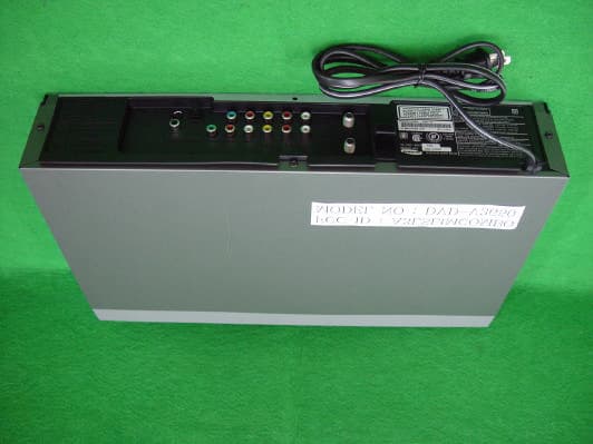
Click to zoom
Application Details
- Equipment Class
- HID - Part 15 TV Interface Device
- Date of Grant
- Jun 01, 2003
- Application Purpose
- Original Equipment
- Date of Application
- Jun 01, 2003
- Equipment Note
- Video Cassette Recorder/ DVD Player
- Frequency Range
- 67.25000000 - 71.75000000
- Company
- Samsung Electronics Co Ltd
- Country
- United States
Documents & Files
Document Text
Text extracted from the exhibit documents filed with the FCC. Open a document above to read the original.
Users Manual
InstructionManualDVD-V3650 www.samsungusa.com EJECT DVD/VCR PROGRESSIVE OPEN/CLOSE POWER 3 2 Important Safety Instructions 1. Read these instructions. 2. Keep these instructions. 3. Heed all warnings. 4. Follow all instructions. 5. Do not use this apparatus near water. 6. Clean only with dry cloth. 7. Do not block any ventilation openings. Install in accordance with the manufacturer’s instructions. 8. Do not install near any heat sources such as radiators, heat registers, or other apparatus (including amplifiers) that produce heat. 9. Do not defeat the safety purpose of the polarized or grounding-type plug. A polarized plug has two blades with one wider than the other. A grounding type plug has two blades and athird grounding prong. The wide blade or the third prong are provided for your safety. If theprovided plug does not fit into your outlet, consult an electrician for replacement of theobsolete outlet. 10. Protect the power cord from being from being walked on or pinched particularly at plugs, convenience receptacles, and the point where they exit from the apparatus. 11. Only use attachments/accessories specified by the manufacturer.12. Use only with cart, stand, tripod, bracket, or table specified by the manufacturer, or sold with the apparatus. When a used, caution when moving the cart/apparatus combination to avoidinjury from tip-over. 13. Unplug this apparatus. When a cart is used, use caution when moving the cart/apparatus combination to avoid injury from tip-over. 14. Refer all servicing to qualified service personnel. Servicing is required when the apparatus has been damaged in any way, such as power-supply cord or plug is damaged, liquid hasbeen spilled or objects have fallen into the apparatus, the apparatus has been exposed torain or moisture, does not operate normally, or been dropped. WARNING:TO PREVENT DAMAGE WHICH MAY RESULT INFIRE OR ELECTRIC SHOCK HAZARD, DO NOTEXPOSE THIS APPLIANCE TO RAIN ORMOISTURE.WARNING:TO AVOID HAZARDOUS EXPOSURE TO INVISIBLELASER RADIATION, DO NOT OPEN ORREMOVE/DEFEAT LASER TRANSPORTPROTECTIVE HOUSING.CAUTION:USE OF ANY CONTROLS, ADJUSTMENTS, ORPROCEDURES OTHER THAN THOSE SPECIFIEDHEREIN MAY RESULT IN HAZARDOUS RADIATIONEXPOSURE. USER/INSTALLER CAUTION:Your authority to operate this FCC certified equipmentcould be voided if you make changes or modificationsnot expressly approved by the manufacturer, who isresponsible for compliance with Part 15 FCC rules.NOTE TO CATV SYSTEM INSTALLER:This reminder is provided to call the CATV systeminstaller’s attention to Article 820-40 of the NationalElectronic Code that provides guidelines for propergrounding and, in particular, specifies that the cableground shall be connected to the grounding system ofthe building, as close to the point of cable entry aspractical. Copy NotificationFederal law provides severe civil and criminal penaltiesfor the unauthorized reproduction, distribution, orexhibition of copyrighted motion pictures andvideotapes. (Title 17, United States Code, Sections501 and 506).Macrovision NotificationThis product incorporates copyright protectiontechnology that is protected by method claims ofcertain U.S. patents and other intellectual propertyrights owned by Macrovision Corporation and otherrights owners. Use of this copyright protectiontechnology must be authorized by MacrovisionCorporation, and is intended for home and otherlimited viewing uses only unless otherwise authorizedby Macrovision Corporation. Reverse engineering ordisassembly is prohibited.CAUTION:To prevent fire, shock hazard, or annoyinginterference, use only the recommended accessories.To prevent electric shock, do not use this (polarized)plug with an extension cord, receptacle, or other outletunless the blades can be fully inserted to prevent bladeexposure. To reduce the risk of electric shock, do notremove the unit cover or back. There are noserviceable parts inside. Refer servicing to qualifiedpersonnel only.CUIDADO:Para prevenir incendio, riesgo de choque, ointerferencia enfadosa, use solamente los accesoriosrecomendados. Para prevenir electrochoque, no useeste enchufe (polarizado) con un cordón de extensión,toma de corriente, o cualquier otra toma a menos quelos dientes puedan ser completamente insertados paraprevenir exposición de los dientes. Para reducir elriesgo de descarga eléctrica, no remueva la cubierta ola parte posterior del equipo. Dentro del equipo no haypartes que requieren servicio. Diríjase solamente apersonal calificado cuando requiera servicio.ATTENTION:Pour éviter les incendis, risque de chocs, ouinterférences fâcheuses, employer seulement lesaccessoires recommandés. Pour éviter les chocsélectriques, ne pas employer cette prise (polarisée)avec une rallonge, une prise de courant ou une autresortie de courant à moins que les lames peuvent êtreinsérées à fond pour l’exposition des lames. Pourréduire les risques de chocs électriques, ne pas retirerle couvercle ou l'arrière du module. Il n'y a pas depièce utilisable à l'intérieur. Ne faire effectuerl'entretien que par un personnel qualifié. This symbol is intended to alertthe user to the presence ofuninsulated dangerous voltagewithin the product’s enclosurethat may be of sufficientmagnitude to constitute risk offire or electric shock.This symbol is intended to alertthe user to the presence ofimportant operating andmaintenance instructions in theliterature accompanying thisproduct. CAUTION FCC Warning Class B Computing Device Information to the User This Equipment has been tested and found to comply with the limits for a class B di gital device pursuant to part 15 of FCC Rule s. These limits are designed to provide reasonable protection agai nst harmful interference in a residential installation. This equipment generates , uses, and can radiate radio frequency energy and, if not installed and used in accord ance with the instructions, may cause harmful interference to ra dio communications. However, there is no guarantee that interference will not occur in…
Text truncated - open the document above for the full version.
External Photos
Photograph of DVD-V3650 - FCC ID : A3LSLIMCOMBO [Front View] [Rear View] [Top View] [Bottom View]
ID Label/Location Info
Location of Rating Label Zoom In
Internal Photos
[Top View – Top Cover Open] [Top of Main PCB View] [Bottom of Main PCB View] Photograph of TM-BLOCK - Type name : TMZH2-013A [Top View] [Bottom View]
Test Report
Project No. : LBE031236 Page 1 of 34 Project No. :LBE031236 Product :Video Cassette Recorder Model No. :DVD-V3650 Date of test :May 27 ~ 28, 2003 Issued Date :May 29, 2003 Tested by: Dong Min , LEE / Test Engineer Reviewed by: No Cheon, PARK / Test Engineer Authorized by: Kyu Baek, CHUNG / Chief of EMC Lab. SAMSUNG ELECTRONICS Co., Ltd. EMC Test Laboratory 416 Maetan-3 Dong, Paldal-Ku, Suwon City, Kyungki-Do, Korea,442-742 Tel. : 81-31-200-2185 Fax. : 81-31-200-2189 This reports shall not be reproduced except in full, without the written approval of SEC EMC Testing laboratory. EMC TEST REPORT Project No. : LBE031236 Page 2 of 34 Table of Contents 1. Introduction & Summary 1.1 Description of the EUT 1.2 Test facility 1.3 Test mode 1.4 Measuring instrument setup 1.5 Test rule and Procedure 1.6 Test Summary 2. Test equipment 3. Test Results 3.1 RADIATED EMISSION MEASUREMENT 3.2 AC POWERLINE CONDUCTED EMISSION MEASUREMENT 3.3 OUTPUT SIGNAL LEVEL MEASUREMENT 3.4 OUTPUT TERMINAL CONDUCTED SPURIOUS EMISSION MEASUREMENT 3.5 ANTENNA TRANSFER SWITCH ISOLATION MEASUREMENT This reports shall not be reproduced except in full, without the written approval of SEC EMC Testing laboratory. Project No. : LBE031236 Page 3 of 34 1. Introduction & Summary 1.1 Description of the EUT Applicant Project Number Equipment Under Test Trade Name Model Number Variant Model Type of RF Output Connector FCC ID Number CH.3 CH.4 Mains input 1.2 Test facility The EMI/EMS measurement facilities used to collect the tested data are located at 416 Maetan 3 Dong, Paldal-Ku, Suwon City, Kyungki Do, Korea. The sites are constructed in conformance with the requirements of ANSI C63.4 and CISPR 16-1 & 16-2. SAMSUNG Electronics Co.,Ltd is accredited by Korea Laboratory Accreditation Scheme(KOLAS) which signed the International Laboratory Accreditation Cooperation (ILAC) Mutual Recognition Arrangement (MRA) for the above test item(s) and test method(s). Measured in Semi-anechoic chamber #1 that is FCC Registration Number 98856. This reports shall not be reproduced except in full, without the written approval of SEC EMC Testing laboratory. Operating(RF Modulator) Frequency Type "F" Connector 75ohm(Unbalanced) A3LSLIMCOMBO 120V 60Hz Visual Carrier 61.25MHz Aural Carrier 65.75MHz Visual Carrier 67.25MHz Aural Carrier 71.75MHz None SAMSUNG SAMSUNG ELECTRONICS Co., Ltd. LBE031236 Video Cassette Recorder DVD-V3650 Project No. : LBE031236 Page 4 of 34 1.3 Test mode The EUT was tested in the following operating modes(at both channel 3 and 4) for the tests mention in this report: 1) Playback mode [ VHS Play] A video tape recorded with VITS signal was played on the EUT. 2) Record mode [ NTSC Signal Input] A NTSC signal(Color bar with grea lines) was supplied at ch. 5(77.25MHz) through the Ant. input connector for recording. 3) Record mode [ 1V VITS Signal Input] A 1V peak-to-peak VITS signal was supplied through the video input connector for recording. 4) Record mode [ 5V VITS Signal Input] A 5V peak-to-peak VITS signal was supplied through the video input connector for recording. 5) Play mode [ DVD Play] Note: The NTSC TV signal input record mode is not applicable to the antenna transfer switch test. 1.4 Measuring instrument setup The explanation of measuring instrument setup when respective function is used in any frequency band is as following: Frequency Band InstrumentDetectorResolutionVideo [MHz]functionBandwidthBandwidth Spectrum analyzerPeak 100kHz (1MHz) 1MHz EMI Test receiverQuasi-Peak120kHz- Above 1000EMI Test receiverAverage1MHz- This reports shall not be reproduced except in full, without the written approval of SEC EMC Testing laboratory. 30 to 1000 Project No. : LBE031236 Page 5 of 34 1.5 Test rule and Procedure FCC Rule Part 15, Subpart B : Unintentional Radiators TV Interface Devices. Test Procedure : ANSI C63.4-1992 1.6 Test Summary Result Pass Pass Pass Pass Pass * N/A : Test not applicable 2. Test equipment EquipmentModel No.Serial No.Makers Last calibration and Interval 8566B3340A21744H.P03/03/04, 12Months Firmware versions : Rev.29.9.86 Quasi-peak adapter85650A2521A00687H.P02/10/09, 12Months RF Preselector85685A2602A00224H.P02/10/09, 12Months ESCS30839809/022R & S02/06/18, 12Months Firmware versions : Main 1.08, OTP 02.01, GRA 02.03 Field strength meterESVP860688/015R & S03/02/28, 12Months L.I.S.NESH3-Z5847265/028R & S02/12/03, 12Months Pattern GeneratorPM5418-TDSILO627116PHILIPS02/12/07, 12Months VITS GeneratorMG318AM08643ANRITSU03/02/18, 12Months Matching PADRAM829712/026R & S- Test ReceiverESI26882692/002R & S02/10/25, 12Months Bi-Log AntennaCBL6112B2766SCHAFFNER03/ 04/26, 12Months This reports shall not be reproduced except in full, without the written approval of SEC EMC Testing laboratory. ANSI C63.4-1992 ANSI C63.4-1992 Applied Standards ANSI C63.4-1992 ANSI C63.4-1992 ANSI C63.4-1992 Spectrum analyzer Field strength meter Test item OUTPUT TERMINAL CONDUCTED SPURIOUS EMISSION ANTENNA TRANSFER SWITCH ISOLATION AC POWERLINE CONDUCTED EMISSION RADIATED EMISSION OUTPUT SIGNAL LEVEL Project No. : LBE031236 Page 6 of 34 3. Test Results 3.1 RADIATED EMISSION MEASUREMENT 3.1.1 Test Procedure Configurate the EUT System in accordance with ANSI C63.4-1992section 8 and 12.2. Power cords for the EUT System are connected the receptacle on the ground plane. The output ports are connected to the cable provided with the device and the ending port of the cable are terminated in the proper impedance. To find out the maximum emission, change the position of the cable, and the EUT operation mode under normal usage of the EUT. The spectrum analyzer are scanned from 30MHz to 1,000MHz in channel 3 and 4. 3.1.2 Setup Photograph This reports shall not be reproduced except in full, without the written approval of SEC EMC Testing laboratory. Project No. : LBE031236 Page 7 of 34 3.1.3 Radiated Emission Test Data The initial step in collecting radiated data was to perform a quasi-peak scan over the measurement range using a receiver. All other emi…
Text truncated - open the document above for the full version.
Test Setup Photos
Project No. : LBE031236 Page 6 of 34 3. Test Results 3.1 RADIATED EMISSION MEASUREMENT 3.1.1 Test Procedure Configurate the EUT System in accordance with ANSI C63.4-1992section 8 and 12.2. Power cords for the EUT System are connected the receptacle on the ground plane. The output ports are connected to the cable provided with the device and the ending port of the cable are terminated in the proper impedance. To find out the maximum emission, change the position of the cable, and the EUT operation mode under normal usage of the EUT. The spectrum analyzer are scanned from 30MHz to 1,000MHz in channel 3 and 4. 3.1.2 Setup Photograph This reports shall not be reproduced except in full, without the written approval of SEC EMC Testing laboratory. Project No. : LBE031236 Page 15 of 34 3.2 AC POWERLINE CONDUCTED EMISSION MEASUREMENT 3.2.1 Reference Rule and Specification FCC Rule Part 15, Section 15.107(a) 3.2.2 Test Procedure 1) Configurate the EUT System in accordance with ANSI C63.4-1992 section 7 and 12.2. Connect the EUT's AC line cord to the EUT port of LISN. 2) All input terminals are terminated in the proper impedance. The output ports are connected to the cable provided with the device and the ending port are terminated in the proper impedance. 3) Using a calibrated coaxial cable, the TEST RECEIVER is connected to the measuring port of the LISN for EUT. To the find out an EUT condition procedures the maximum emission, the position of cables, EUT operations mode are the position of cables, EUT operations mode are checked under normal usage of EUT. Then, the emission are scanned from 0.15MHz to 30MHz relative to the limit are recorded. 3.2.3 Setup Photograph This reports shall not be reproduced except in full, without the written approval of SEC EMC Testing laboratory. Project No. : LBE031236 Page 26 of 34 3.3 OUTPUT SIGNAL LEVEL MEASUREMENT 3.3.1 Test Procedure Configurate the EUT System in accordance with ANSI C63.4-1992 section 12.2. The RF output terminal is connected is to the spectrum analyzer through the matching transformer with a calibrated 75 ohms coaxial cable. Then, the RF output signal level is measured under the EUT condition produces the maximum signal level. 3.3.2 Setup Photograph This reports shall not be reproduced except in full, without the written approval of SEC EMC Testing laboratory. Project No. : LBE031236 Page 30 of 34 3.4 OUTPUT TERMINAL CONDUCTED SPURIOUS EMISSION MEASUREMENT 3.4.1 Test Procedure The EUT system and measuring instrument are set up in the same manner of the output signal measurement. The spectrum was scanned from 30MHz to more than 4.6MHz below the visual carrier frequency, and from more than 7.4MHz above the visual carrier frequency to 1000MHz. Then, the significant spurious emissions are measured at the output terminal. 3.4.2 Setup Photograph This reports shall not be reproduced except in full, without the written approval of SEC EMC Testing laboratory. Project No. : LBE031236 Page 33 of 34 3.5 ANTENNA TRANSFER SWITCH ISOLATION MEASUREMENT 3.5.1 Test Procedure Configurate the EUT System in accordance with ANSI C63.4-1992 section 12.2. The RF output terminal is terminated in the proper impedance. The ANT input terminal is connected is to the spectrum analyzer through the matching transformer with a calibrated 75 ohms coaxial cable. Then, the RF output leakage level is measured under the EUT condition produces the maximum signal level. 3.5.2 Setup Photograph This reports shall not be reproduced except in full, without the written approval of SEC EMC Testing laboratory.
Contact Information
Applicant
Jenni Chun(General Manager)
Technical Contact
PCTEST Engineering Lab., Inc.Randy Ortanez
[email protected]410-290-6652
6660-B Dobbin Road · Columbia, Maryland · United States
Test Firm
SAMSUNG ELECTRONICS CO., LTD.No Cheon Park
Technical Specifications
| # | Rule Parts | Frequency Range | Power Output |
|---|---|---|---|
| 2 | 15B | 67.25 MHz - 71.75 MHz | - |
Other Applications from Samsung Electronics Co Ltd
A3LSMS741B
Aug 05, 2026Portable Handset
Equipment Class
6VL - 15E 6 GHZ Very Low Power DeviceA3LSMX940
Jul 31, 2026BT,BLE Tablet DTS,UNII a,b,g,n,ac,ax,be and digitizer
Equipment Class
DTS - Digital Transmission SystemA3LSMS741U
Jul 30, 2026Portable Handset
Equipment Class
6CD - 15E 6 GHz Low Power Dual ClientA3LSMX840
Jul 27, 2026BT,BLE Tablet DTS,UNII a,b,g,n,ac,ax and Digitizer
Equipment Class
DSS - Part 15 Spread Spectrum TransmitterA3LSMX848U
Jul 27, 2026WCDMA, LTE, 5G NR Tablet BT,BLE, DTS,UNII a b g n ac ax and Digitizer
Equipment Class
JBP - Part 15 Class B Computing Device Peripheral