A3LSM352Internal CD-RW / DVD Drive
Samsung Electronics Co Ltd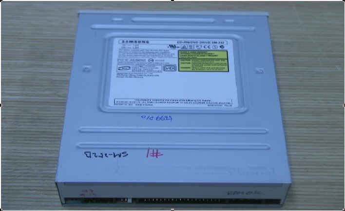
Click to zoom
Application Details
- Equipment Class
- JBP - Part 15 Class B Computing Device Peripheral
- Date of Grant
- Feb 11, 2003
- Application Purpose
- Original Equipment
- Date of Application
- Feb 11, 2003
- Equipment Note
- Internal CD-RW / DVD Drive
- Company
- Samsung Electronics Co Ltd
- Country
- United States
Documents & Files
Document Text
Text extracted from the exhibit documents filed with the FCC. Open a document above to read the original.
Users Manual
COMBO DRIVESM-352 User’s Guide FCC Compliance This equipment has been tested and found to comply with the limits for a Class Bdigital device, pursuant to Part 15 of the FCC rules.These limits are designed to provide reasonable protection against harmfulinterference in a residential installation.This equipment generates, uses, and can radiate radio frequency energy and,if not installed and used in accordance with the instructions, may cause harmfulinterference to radio communications. However, there is no guarantee thatinterference will not occur in a particular installation.If this equipment does cause harmful interference to radio or television reception,which can be deter-mined by turning the equipment off and on, the user isencouraged to try to correct the interference by one or more of the followingmeasures: Re-orient or relocate the receiving antenna.Increase the separation between the equipment and receiver.Connect the equipment into an outlet on a circuit different from that to whichthe receiver is connected.Consult the dealer or an experienced radio/TV technician for help. Contents 2 Safety Precautions 3 ENGLISH The following diagrams illustrate the precautions to be taken when usingyour COMBO drive. ✱ Changes or modifications not expressly approved by the party responsible forcompliance could void the user s authority to operate the equipment. You must not use the drive in any manner other than that specified in this guide. Avoid exposing your eyes or skin to direct or scattered radiation. CAUTION Do not attempt to repair the COMBO drive yourself.Contact your dealer or local SAMSUNG representative for all repairs.If you make any adjustments or perform any operations other than thosespecified in this guide, you run the risk of exposure to hazardous radiation. WARRANTY Please refer to the Samsung limited warranty statements. PRECAUTIONS 1. To reduce the risk of fire or electric shock, do not expose this appliance to rain or moisture. 2. Always check each disc for cracks before using it. If there are cracks on the surfaces, especially around the border of the centerhole, we recommend that you make a copy of the disc immediatelyand then stop using it. If you continue using the disc, it will probablydevelop more cracks and eventually cause irreparable damage. 3. Do not use poor quality discs: From unknown sourcesWithout any copyrightScratched or damaged in any way Safety Precautions 3 Your COMBO Drive 4 Upgrading the Firmware Flash Memory 5 System Requirements 5 Installing the COMBO Drive 6 Connecting the Cables 6 Installing the CD Record Utility 9 Installing the Device Driver 9 Setting Up the Device Driver 10 Recommended Disc Types 10 Using the COMBO Drive 11 Storing and Cleaning Your Discs 11 Solving Recording Problems 12 Caution with errors 14 Term Description 15 Recommended Disc Type 15 General DMA Installation Guide 15 Solving Technical Problems 16 Technical Specifications 18 * All product names mentioned in this document are trademarks or registered trademarks of their respective owners. ENGLISH 5 Upgrading the Firmware Flash Memory Your COMBO Drive 4 1. Connector for stereo headphones with a 3.6 mm stereo mini-jack2. Headphone volume control3. Disc compartment (the compartment opens and closes automatically when you press the Eject button) 4. Emergency eject hole (if the compartment does not open when you press the Eject button, power off the computer, insert a pin orunfolded paper clip in the hole and push firmly) 5. Indicator light6. Eject button The product firmware can be upgraded by downloading the updated file from thefollowing Web site: http:// www.samsung-ODD.com/odd www.samsungelectronics.com System Requirements Before you install the COMBO drive, we strongly recommend that you check thatyour setup meets the system requirements listed below.Item Description Computer Intel Pentium II 300MHz/Celeron 333A(or higher), 32 MB of RAM (or higher) with an IDE interface Free expansion unit 5.25 inch Disk space 700 MB minimum Windows version Windows 98/2000/ME/XP/NT4.0 (or higher) (For Windows NT, we recommend Service Pack2,and Version is over 4.00.1381) MS-DOS 5.0 or higher (For MS-DOS, The CD-R/CD-RW driver can only read a disc without premaster Software.) DVD Video playback PC with Windows 98/2000/ME/XP/NT4.0 DVD-Video playback software and appropriatehardware (the Power DVD MPEG software isincluded in the COMBO drive package) 1. Two-pin digital audio output terminal for use with a sound or MPEG card supporting digital audio features 2. Four-pin sound output terminal for use with a sound card (refer to the sound card documentation for further details) 3. Master/slave select terminal4. 40pin host E-IDE interface connector5. 4pin power terminal 12 3 456 1 23 4 5 DVD Region Protection Coding (RPC): The RPC feature is supported on DVD players and is used with DVD-video discs(such as movies). Currently, the motion picture industry has divided the world intodifferent regions or zones that correspond to the regional markets into which themotion picture industry releases movies. Simply put, RPC codes are placed on moviesmarketed throughout the world, based on the region of the world in which they arebeing sold. These RPC codes help control and prevent pirating of new movies intoother motion picture regions prior to their true release dates within those markets.The SM-352 COMBO drive supports RPC phase II. In the RPC-2 mode, the localcode can be changed by users.RPC-2 is selected by default for the SM-352 COMBO drive.You can change the region code up to five times via an MPEG application.Please contact your dealer or local SAMSUNG representative if you wish to changethe local code more than five times. ENGLISH 7 6 Installing the COMBO DriveConnecting the Cables To install your COMBO drive in the PC, proceed as follows.1 Make sure that the PC is powered off and disconnected from any power source. 1 Connecting the power cableThe 4-pin power cable from the internal power unit of your com…
Text truncated - open the document above for the full version.
Block Diagram
. ~2:I C ~-,-L- ~ '+ ~ Ae"&+ z 0 c W -J J: q ~ is .:. -- ,\E'E" ?, + r '" ~ N ~ a: ~ ~,.. ~c 16 ~c - .. .. c 00, c > c 0" c ~ II: ~ ~ ~ z C oct 9 t T ci >"" -M u >N aj.: >U- _W <> ... ~ !:: CD <0 .- ~I ~I Do ~ -- -f'rl,,"r -' w ~I ~>. - "' 0/. +, a: a: ww $:~ oa: n n 10, ~ ~ (0 ~ ~ C!) I' - OSIiL nRn"' 00 -'~ - no..." -- moa 6 LL !? z :9 Ii: + ~ z e II I' . . . .9 + q + Z q ~ ~ "- > ~ f T ~... ~ Cf -' l' :; II) + :; r(\ Z :J '" @ ~ I' <: .{ r I T ~ Ii: '" ~ ~ 1'- CD a' '" z :J rl' ~ + ~ ~I z a: ,. ~~ - ') f l- => 0 0 c z (!) c II
External Photos
Product-front Product-back
ID Label/Location Info
Page 17 of 18 Project NO. : LBE030217 5. FCC Label Configuration and Location 5.1 Label Configulation 5.2 Location of Label This report shall not be reproduced except in full, without the written approval of SEC EMC Testing laboratory.
Internal Photos
PCB-front PCB-back
Test Report
Page 1 of 18 Project NO. : LBE030217 Product :CD-RW/DVD DRIVE Model No. : SM-352(Ver.B) FCC ID : A3LSM352 1. This test reports shall not be reproduced except in full, without the written approval of SEC EMC Testing laboratory. 2. This test reports does not constitute an endorsement by NIST/NVLAP or U.S Government. 3. This test report is to certify that the tested device properly complies with the requirements of FCC Rules and Regulations Part 15 Subpart B Unintentional Radiators. All tests necessary to show compliance to the requirements were and these results met the specifications requirement. Date of test :January 23, 2003 ~ January 24, 2003 Issued Date :February 4, 2003 Tested by: Jin Hwan, Jung/ Test Engineer Reviewed by: Yang Soo, KIM / Manager of EMC Lab. Authorised by: Kyu Baek, CHUNG / Chief of EMC Lab. This laboratory is registered by the NIST/NVLAP, U.S.A. The test reported herein have been performed in accordance with its terms of registration. EMI TEST REPORT According to FCC Part 15 Subpart B/Class B NVLAP Code: 200447 Page 2 of 18 Project NO. : LBE030217 Table of Contents 1. General Information 1.1 Product Description 1.2 Configuration of EUT and peripherals 1.3 Used Cable Description 1.4 System Block Diagram of Test Configuration 1.5 Test Facility 2. System Test Configuration 2.1 Configuration of Radiated and Conducted Interference Measurement 2.2 Operation Environment 2.3 Test Procedure 3. Conducted Emission Test Data 4. Radiated Emission Test Data 5. Label Configuration and Location 6. Test Equipment Used Distribution This test report has been made available as follows: CS Management Center, EMC Laboratory1 original OMS Division1 copy This report shall not be reproduced except in full, without the written approval of SEC EMC Testing laboratory. Page 3 of 18 Project NO. : LBE030217 1. General Information Applicant :Samsung Electronics Co., Ltd. Digital Media Network, OMS Division Full Address :416 Maetan 3 Dong, Paldal-Ku, Suwon City, Kyungki Do, Korea, 442-742 Kind of Product :CD-RW/DVD DRIVE FCC ID:A3LSM352 Project Name :- Model & Variant Names : SM-352(Ver.B) (Brand Name: Samsung) Test Report Produced by :Jin Hwan, Jung/ Test Engineer This report shall not be reproduced except in full, without the written approval of SEC EMC Testing laboratory. Page 4 of 18 Project NO. : LBE030217 1.1 Product Description 1) Justification The system was configured for testing in typical fashion use. Cable were attached to each of the available I/O Ports. Where applicable, peripherals were attached to the I/O cables. The mode of operation utilized for testing was selected to best simulate typical EUT use. The system was pre-tested using the below additional components, and we found worst emission level for the components, were selected as the final components for the test. And then the system was tested with the configuration of clause 1.4 In each test mode, Finally we found worst case emission that is above configuration with the Worst case components(in the above table). So, the DATA of the maximum EUT operation was reported. Further details of cabling and configuration are shown in the test system configuration. This report shall not be reproduced except in full, without the written approval of SEC EMC Testing laboratory. Compaq Ear-PhoneSony Pavilion 8871 CX151S M-U48a SDM4540UL - ComponentBrand and Model NameRemark Key-Board Computer LCD Monitor Mouse Compaq Samsung Logitech CD-RW/DVD Drive Printer EUT/Samsung CANON AC AdapterTABUCHI BJC-50 SM-352(Ver.B) K30088 Page 5 of 18 Project NO. : LBE030217 2) Operating Frequency : 1. Resonator : 33.86Mhz 2. HFM : 250~300 Mhz 3) Description of Testing operating mode 4) Manufacturer : SAMSUNG Electronics Co., Ltd. This report shall not be reproduced except in full, without the written approval of SEC EMC Testing laboratory. CD-ROM MODE CD-RW MODE DVD-ROM MODE Operating Mode Operating section of EUT CD-R MODE CD-ROM MODE Continously Audio CD playing by EUT Page 6 of 18 Project NO. : LBE030217 1.2 Configuration of EUT and peripherals MarkItemModel No.Serial No.ManufacturerFCC ID A CD-RW/DVD DRIVE SM-352(Ver.B)NoneSamsungEUT BD/T PCPavilion 8871 KR11106864 HP- CPrinterBJC-50 CLG010600281 CANON - DLCD MonitorCX151S N192H4LT105171Samsung- EUSB Key-BoardSDM4540UL B354ALP0BL1VKW Compaq- FUSB MouseM-U48aLZE95183958Logitech- GAC AdapterK30088CLG010600281TABUCHI- HEar-PhoneNoneNoneSony- This report shall not be reproduced except in full, without the written approval of SEC EMC Testing laboratory. Page 7 of 18 Project NO. : LBE030217 1.3 Used Cable Description No.ItemLength[m]Shielded (Y/N)Remark 1AC Power Cable1.7N- 2Monitor Cable1.2Y- 3Mouse Cable1.2N- 4Key-Board Cable1.2N- 5AC Power Cable1.7N- 6Ear-Phone Cabe0.7N- 7AC Power Cable1.7N This report shall not be reproduced except in full, without the written approval of SEC EMC Testing laboratory. Page 8 of 18 Project NO. : LBE030217 1.4 System Block Diagram of Test Configuration 1.5 Test Facility All test described in this report were performed by : SAMSUNG ELECTRONICS CO., LTD. EMC TESTING LABORATORY 416 Maetan 3 Dong, Paldal-Ku, Suwon City, Kyungki Do, Korea, 442-742 Semi Anechoic Chamber #2(Registration Number:873282) and Shielded Room. This test facility has been filed in FCC under the criteria in ANSI C63.4-1992. This report shall not be reproduced except in full, without the written approval of SEC EMC Testing laboratory. F B E A AC POWER AC POWER 1 2 3 4 5 H 6 D G C AC POWER 7 Page 9 of 18 Project NO. : LBE030217 2. System Test Configuration 2.1 Configuration of Radiated and Conducted Interference Measurement * Cabling was taken into consideration and test data was taken under worse case conditions. 1)Conduction(Front View) 2)Conduction(Rear View) This report shall not be reproduced except in full, without the written approval of SEC EMC Testing laboratory. Page 10 of 18 Project NO. : LBE030217 3) Radiation(Front View) 4) Radiation(Rear View) This report shall not be reproduced except in full, wi…
Text truncated - open the document above for the full version.
Test Setup Photos
Page 9 of 18 Project NO. : LBE030217 2. System Test Configuration 2.1 Configuration of Radiated and Conducted Interference Measurement * Cabling was taken into consideration and test data was taken under worse case conditions. 1)Conduction(Front View) 2)Conduction(Rear View) This report shall not be reproduced except in full, without the written approval of SEC EMC Testing laboratory. Page 10 of 18 Project NO. : LBE030217 3) Radiation(Front View) 4) Radiation(Rear View) This report shall not be reproduced except in full, without the written approval of SEC EMC Testing laboratory.
Contact Information
Applicant
Jenni Chun(General Manager)
Technical Contact
PCTEST Engineering Lab., Inc.Randy Ortanez
[email protected]410-290-6652
6660-B Dobbin Road · Columbia, Maryland · United States
Test Firm
PCTEST Engineering Laboratory, Inc.Randy Ortanez
Technical Specifications
| # | Rule Parts | Frequency Range | Power Output |
|---|---|---|---|
| 1 | 15B | - | - |
Other Applications from Samsung Electronics Co Ltd
A3LSMS741B
Aug 05, 2026Portable Handset
Equipment Class
6VL - 15E 6 GHZ Very Low Power DeviceA3LSMX940
Jul 31, 2026BT,BLE Tablet DTS,UNII a,b,g,n,ac,ax,be and digitizer
Equipment Class
DTS - Digital Transmission SystemA3LSMS741U
Jul 30, 2026Portable Handset
Equipment Class
6CD - 15E 6 GHz Low Power Dual ClientA3LSMX840
Jul 27, 2026BT,BLE Tablet DTS,UNII a,b,g,n,ac,ax and Digitizer
Equipment Class
DSS - Part 15 Spread Spectrum TransmitterA3LSMX848U
Jul 27, 2026WCDMA, LTE, 5G NR Tablet BT,BLE, DTS,UNII a b g n ac ax and Digitizer
Equipment Class
JBP - Part 15 Class B Computing Device Peripheral