A3LSP10Notebook PC
Samsung Electronics Co Ltd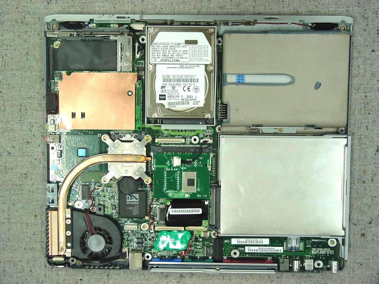
Click to zoom
Application Details
- Equipment Class
- JBC - Part 15 Class B Computing Device/Personal Computer
- Date of Grant
- Jun 12, 2002
- Application Purpose
- Original Equipment
- Date of Application
- Jun 12, 2002
- Equipment Note
- Notebook PC
- Company
- Samsung Electronics Co Ltd
- Country
- United States
Documents & Files
Document Text
Text extracted from the exhibit documents filed with the FCC. Open a document above to read the original.
Users Manual
Notices i Notices No part of this publication may be reproduced, stored in a retrieval system, or transmitted, in any form or by any means, mechanical photocopying, recording or otherwise, without the prior written permission of the manufacturer. The information within this manual is subject to change without notice. The manufacturer shall not be held liable for technical or editorial errors or omissions contained in herein; nor for incidental or consequential damages resulting from the furnishing, performance or use of this material. Microsoft Windows is a registered trademark of the Microsoft Corporation. Product names mentioned herein are for identification purposes only, and may be trademarks and/or registered trademarks of their respective companies. Macrovision Statement If your computer has a DVD drive and an analog TV Out port, the following paragraph applies: This product incorporates copyright protection technology that is protected by method claims of certain U.S. patents and other intellectual property rights owned by Macrovision Corporation and other rights owners. Use of this copyright protection technology must be authorized by Macrovision Corporation, and is intended for home and other limited viewing uses only unless otherwise authorized by Macrovision Corporation. Reverse engineering or disassembly is prohibited. Copyright 2002 All rights are reserved ii Users Manual Important Safety Information Safety Instructions Your system is designed and tested to meet the latest standards for safety of information technology equipment. However, to ensure safe use of this product, it is important that the safety instructions marked on the product and in the documentation are followed. Always follow these instructions to help guard against personal injury and damage to your system. i Setting Up your System • Read and follow all instructions marked on the product and in the documentation before you operate your system. Retain all safety and operating instructions for future use. •Do not use this product near water or a heat source such as a radiator. •Set up the system on a stable work surface. •The product should be operated only with the type of power source indicated on the rating label. •Ensure that the electrical outlet you are using to power your equipment is easily accessible in case of fire or short circuit. •If your computer has a voltage selector switch, make sure that the switch is in the proper position for your area. •Openings in the computer case are provided for ventilation. Do not block or cover these openings. Make sure you provide adequate space, at least 6 inches (15 cm), around the system for ventilation when you set up your work area. Never insert objects of any kind into the computer ventilation openings. •Ensure that the fan vents on the bottom of the casing are clear at all times. Do not place the computer on a soft surface, doing so will block the bottom vents. •If you use an extension cord with this system, make sure that the total ampere rating on the products plugged into the extension cord does not exceed the extension cord ampere rating. Important Safety Information iii Care During Use • Do not walk on the power cord or allow anything to rest on it. •Do not spill anything on the system. The best way to avoid spills is to not eat or drink near your system. •Some products have a replaceable CMOS battery on the system board. There is a danger of explosion if the CMOS battery is replaced incorrectly. Replace the battery with the same or equivalent type recommended by the manufacturer. Dispose of batteries according to the manufacturer’s instructions. If the CMOS battery requires replacement insure that a qualified technician performs the task •When the computer is turned off, a small amount of electrical current still flows through the computer. To avoid electrical shock, always unplug all power cables, remove the battery and modem cables from the wall outlets before cleaning the system. •Unplug the system from the wall outlet and refer servicing to qualified personnel if: – The power cord or plug is damaged. – Liquid has been spilled into the system. – The system does not operate properly when the operating instructions are followed. – The system was dropped or the casing is damaged. – The system performance changes. Replacement Parts and Accessories Use only replacement parts and accessories recommended by manufacturer. To reduce the risk of fire, use only No. 26 AWG or larger telecommunications line cord. Written by: Daryl L. Osden Do not use this product in areas classified as hazardous. Such areas include patient care areas of medical and dental facilities, oxygen rich environments, or industrial areas. iv Users Manual Battery Disposal Do not put rechargeable batteries or products powered by non-removable rechargeable batteries in the garbage. Contact the Samsung Helpline for information on how to dispose of batteries that you cannot use or recharge any longer. Follow all local regulations when disposing of old batteries. Regulatory Compliance Statements v Regulatory Compliance Statements Wireless Guidance Low power, Radio LAN type devices (radio frequency (RF) wireless communication devices), operating in the 2.4 GHz Band, may be present (embedded) in your notebook system. The following section is a general overview of considerations while operating a wireless device. Additional limitations, cautions, and concerns for specific countries are listed in the specific country sections (or country group sections). The wireless devices in your system are only qualified for use in the countries identified by the Radio Approval Marks on the system rating label. If the country you will be using the wireless device in, is not listed, please contact your local Radio Approval agency for requirements. Wireless devices are closely regulated and use may not be allowed. The power output of the wireless device or devices that may be embedded in your notebook is well bel…
Text truncated - open the document above for the full version.
Users Manual
34 Users Manual Working with PC Cards By installing PC Cards, you can add functions to your notebook computer similar to those found on add-in boards for desktop computers. Available PC Cards include: •Input/output, such as modem, network, video capture, and SCSI cards. •Storage, such as hard drive and flash memory cards. Your computer includes the following PC Card support: •One PC-Card slot: You can install Type I or II cards in the slot. •CardBus hardware and software: CardBus enables the computer to use 32-bit PCMCIA Cards. Windows supports 32-bit and 16-bit PC Cards. Maintaining PC Cards To maintain your PC Cards, follow these guidelines: •Keep cards away from excessive heat, direct sunlight, and liquids. •Do not drop, bend, flex, or crush cards when handling. •Keep dust, magnets, and static electricity away from PC Cards. •When a card is not in use, carry it in its protective carrying case. •Some PC Cards include cables that extend from the back of the cards. Be careful not to bend or put excessive strain on these cables. Taurus (Windows XP) - English.fm Page 34 Thursday, March 28, 2002 6:06 PM Working with PC Cards 35 Using PC Cards To insert a PC Card into a slot: 1.Push the slot door in with the PC Card. 2.Align the card with a slot and insert the card into the slot until it locks in place. Windows automatically assigns computer resources (such as communication ports and memory addresses) to a PC Card installed in your computer. To remove a PC Card from your computer: Use the following procedures to remove PC Cards, or you may lose data that is being stored to a card. 1.Click icon on the taskbar. 2.Select the card currently in use, and click the Stop button. The eject button for the card slot operates in two steps, therefore to remove a PC Card: 3.Push the eject button once to pop it outward then push the eject button again to eject the card. 4.Pull the card out of the PC Card slot. PC Card : Insert PC card with product information facing up PCMCIA Card Eject button PCMCIA Card Eject button Taurus (Windows XP) - English.fm Page 35 Thursday, March 28, 2002 6:06 PM 36 Users Manual Multi Media Functions/Equipment Media Player The Windows Media player is used to play audio files while the computer is on. You can play audio/video CD files using the Windows Media Player, as well as watching TV, video and listening to the radio through internet. The instructions to play a video CD-ROM are the same as the instructions for the audio CD below. Playing a Audio/Multimedia CD To play an CD follow the instructions below: 1.Insert a compact disc into your CD-ROM drive. 2.Press the eject button on the CD-ROM drive to open the CD-ROM device. 3.Insert a CD, label side up. 4.Carefully push the tray in to close the drive tray. The Windows Media Player button appears on the taskbar if not already there, and the music begins to play. If the disk does not play click Start > All Programs > Accessories > Entertainment > Windows Media Player. CD LED On: A LED on the drive tray is on when the computer is reading from a CD. Do not remove a disc when this LED is on. Removing the Audio/Multimedia CD To remove the CD follow the instructions below: 1.Click Start > All Programs > Accessories > Entertainment > Windows Media Player to open the Windows Media Player window, if not already open. 2.Click Stop in the Windows Media Player window or simply close the Windows media player. 3.Press the button on your CD-ROM drive. The drive tray opens and you can remove the CD from the CD-ROM drive. 4.For more information on playing compact discs, see the Help menu in the Windows Media Player window. Taurus (Windows XP) - English.fm Page 36 Thursday, March 28, 2002 6:06 PM Multi Media Functions/Equipment 37 Audio DJ The Audio DJ can play music CDs and MP3 files while the computer is off. It will not, however play video CDs. Button Operation The buttons & display for the Audio DJ operate as follows: ButtonNameFunction Volume DownDecreases speaker volume when Audio DJ is on. Volume UpIncreases speaker volume when Audio DJ is on. MUTEPress the <Volume Down + Volume Up> buttons simultaneously for ~ 1 sec. to mute the sound. Track DisplayIndicates power on => and total tracks available on CD and track playing => . The blinks when the music file is paused. Stop/Eject Stops & Ejects the Audio CD. Press the button ~ 3 seconds to turn off power. Audio DJ Power CD Play/Pause Starts/Pauses the Audio CD and MP3 Files. Previous Track/Song Fast Search Reverse Changes the Audio CD to the previous track/song. Next Track/Song Fast Search Forward Changes the Audio CD to the next track/song. LockPress the <Stop/Eject + Volume Down> buttons simultaneously for ~ 3 sec. to lock the Audio DJ buttons. This prevent changing settings while transporting the computer. UnlockPress the <Audio DJ Power CD Play/Pauset + Volume Down> buttons simultaneously for ~ 3 sec. to unlock the Audio DJ buttons. + + + Taurus (Windows XP) - English.fm Page 37 Thursday, March 28, 2002 6:06 PM 38 Users Manual Using the Audio DJ Play an Audio CD 1.Verify the computer is off and that a CD-ROM device is in the flex-bay. Audio DJ Power Buttons: If a CD-ROM device is not in the flex-bay, the Audio DJ power button will not energize the Audio DJ player. Computer Button Operation: All computer and SENS keyboard buttons are non functional while Audio DJ is operating except the Computer Power Button. 2.Press the Audio DJ power button until the icon is displayed in the track display window [Labeled: DIGITAL AUDIO]. 3.Press the eject button on the CD-ROM drive or the button on the Audio DJ button bar. 4.Insert a Audio CD into your CD-ROM drive label side up. 5.Press the button on the Audio DJ. Pause/Resume an Audio CD 1.Press the CD button to pause the CD. 2.Press the button again to restart the CD. Stop an Audio CD 1.Press the button to stop and eject the CD. 2.Remove the Audio CD, then close the tray. 3.Press the Audio DJ power button for ~ 1 second to turn off the Audio DJ playe…
Text truncated - open the document above for the full version.
Block Diagram
Bluetooth Touch Connector ATI M7-P DC/DC PG 35 PG 20 PV-1.0 ICH3-M SIO, PIO PG 10,11,12 PG 9 DC/DC MINIPCI 421 BGA Damping PG 14 Graphics PC87391 PG 26 FAN CPU PG 34 PS/2 Power IEEE1394 Mobile Processor Rev. PG 9 PG 6 8Bit, 1.8V, 266MB/S SMC/KBC Audio Clocking PG 27 USB0 PG 39 PSB PG 13 PG 13 AC97’ Primary Wireless LAN LAN Video H-PHONE 266MHz, 1.06GB/S Brookdale L1 Cache : 12KB HDD TAURUS Block Diagram AGP4x, 1.5V, 1.06GB/S Hub Interface CPU Thermal PG 16,17,18 2nd HDD RJ11 USB1 Combo USB3 CH.1 PG 7,8 FWH PG 19 400MT/S Battery Opmized Mode : 1.2V, 1.2GHz 33MHz, 3.3V PCI Super I/O DDR-SODIMM 0 PC1600, DDR 2.5V LCD PG 18 USB2 PG 38 Memory PG 24 MIC,H-Phone,SPDIF PG 40 MDC Modem Sensor Module Docking Hitachi H8S PG 32 PG 29 PG 34 VIDSelector 22P/40P Connector PG 41 Charging Circuit ? BGA ANT CPU Kinnereth Parallel A USB0 Connector CD-RW 2169 ScanKBD Secondary IDE CRT PG 31 Serial 4 PG 28 CS4299 ANT SwapBay Local PG 36 Primary IDE FINGER PRINT USB 1.1 DDR-SODIMM 1 RJ45 FIR Mouse,KBD B SAMSUNG (DDR) PAD C 30Pin Connector PG 36 PG 30 EXCEPT AS AUTHORIZED BY SAMSUNG. 14.1" FDDCD/DVD Life Time > 3Hrs 4 2 (IMVP-III) Smart Battery 2 Northwood PG 39 CARDBUS 478pin PG 27 AC97 ’ Secondary 4pin PROPRIETARY INFORMATION THAT IS C SAMSUNG PROPRIETARY 3.3V LPC, 33MHz PG 35 Module SVHS, DVI, CRT SVHS BluebirdVL B D DVD-Combo Option 3 Floppy BUS PG 25 DO NOT DISCLOSE TO OR DUPLICATE FOR OTHERS THIS DOCUMENT CONTAINS CONFIDENTIAL 1 MIC-IN ELECTRONICS SEPT, 11, 2001 14:45:00 PM MEMORY STICK Docking USB1 3 PG 37 SOCKET SAMSUNG ELECTRONICS CO ’ S PROPERTY. System A 1394 PG 17 1 L2 Cache : 256KB IEEE1394 R5C551 D U-ATA 100 CH.0
ID Label/Location Info
Page 16 of 17 Project NO. : E1-02-0120 5. FCC Label Configuration and Location 5.1 Label Configulation 5.2 Location of Label This report shall not be reproduced except in full, without the written approval of SEC EMC Testing laboratory.
Test Report
Page 1 of 17 Project NO. : E1-02-0120 Product : Notebook PC Model No. : P10 FCC ID : A3LSP10 1. This test reports shall not be reproduced except in full, without the written approval of SEC EMC Testing laboratory. 2. This test reports does not constitute an endorsement by NIST/NVLAP or U.S Government. 3. This test report is to certify that the tested device properly complies with the requirements of FCC Rules and Regulations Part 15 Subpart B Unintentional Radiators. All tests necessary to show compliance to the requirements were and these results met the specifications requirement. Date of test : April 2, 2002 ~ April 10, 2002 Issued Date : April 12, 2002 Tested by: Il Kweon, BAE / Test Engineer Reviewed by: Yang Soo, KIM / Manager of EMC Lab. Authorised by: Kyu Baek, CHUNG / Chief of EMC Lab. This laboratory is registered by the NIST/NVLAP, U.S.A. The test reported herein have been performed in accordance with its terms of registration. EMI TEST REPORT According to FCC Part 15 Subpart B/Class B NVLAP Code: 200447 Page 2 of 17 Project NO. : E1-02-0120 Table of Contents 1. General Information 1.1 Product Description 1.2 Configuration of EUT and peripherals 1.3 Used Cable Description 1.4 System Block Diagram of Test Configuration 1.5 Test Facility 2. System Test Configuration 2.1 Configuration of Radiated and Conducted Interference Measurement 2.2 Operation Environment 2.3 Test Procedure 3. Conducted Emission Test Data 4. Radiated Emission Test Data 5. Label Configuration and Location 6. Test Equipment Used Distribution This test report has been made available as follows: CS Management Center, EMC Laboratory 1 original Computer Division 1 copy This report shall not be reproduced except in full, without the written approval of SEC EMC Testing laboratory. Page 3 of 17 Project NO. : E1-02-0120 1. General Information Applicant : Samsung Electronics Co., Ltd. Full Address :416 Maetan 3 Dong, Paldal-Ku, Suwon City, Kyungki Do, Korea, 442-742 Kind of Product :Notebook PC FCC ID:A3LSP10 Project Name :Taurus Model & Variant Names : P10 (Brand Name: Samsung) Test Report Produced by :Il Kweon, BAE / Test Engineer This report shall not be reproduced except in full, without the written approval of SEC EMC Testing laboratory. Page 4 of 17 Project NO. : E1-02-0120 1.1 Product Description 1) Justification The system was configured for testing in typical fashion use. Cable were attached to each of the available I/O Ports. Where applicable, peripherals were attached to the I/O cables. The mode of operation utilized for testing was selected to best simulate typical EUT use. The system was pre-tested using the below additional components, and we found worst emission level for the components, were selected as the final components for the test. - Samsung, SN-124P - Teac CD-224EC - Matsushita, UJDA-340A - Teac DV-28E-B - Samsung, SN-308B - Toshiba, SD-R2102 - Teac, FD-05HG - SEM, SWB-1000m - Agere, MPCI3A-20/R - SGS, ST92163 - Samsung, SMB-2000W - Samsung, SPR-P10E And then the system was tested with the configuration of (A), (B), (C), (D) below (A) CPU Pentium IV 1800MHz without Port Replicator, Worst-Case-1. (B) CPU Pentium IV 1800MHz with Port Replicator, Worst-Case-1. (C) CPU Pentium IV 1800MHz without Port Replicator, Worst-Case-2. (D) CPU Pentium IV 1800MHz with Port Replicator, Worst-Case-2. In each test mode, Finally we found worst case emission that is above (A) configuration with the Worst case components(in the above table). So, the DATA of the maximum(worst case 1) EUT operation was reported. Further details of cabling and configuration are shown in the test system configuration. This report shall not be reproduced except in full, without the written approval of SEC EMC Testing laboratory. Port Replicator Worst Case 1, 2 Finger Print Worst Case 1 Memory Stick Worst Case 2 Bluetooth Wireless LAN FDD Worst Case 1 Worst Case 1 Worst Case 2 DVD_CDRW_Combo DVD_CDRW_Combo DVD Worst Case 2 ComponentBrand and Model NameRemark CD-RW CD-ROM CD-ROM Page 5 of 17 Project NO. : E1-02-0120 2) Operating Frequency : 1800MHz(CPU Speed), 100MHz(Host Clock), 133MHz(SDRAM Clock), 8M(Finger print) 33.3MHz(PCI Clock), 14.318MHz(Ref), 49.512MHz(Audio Clock), 25M(Network) 183MHz(Video Memory Clock), 12.288MHz(Audio Bit Clock), 24.576MHz(Audio C24) 10MHz(Micom Clock), 48MHz(USB Clock), 66.6(Hub), 65MHz(14.1" LCD Clock) 3) Description of Testing operating mode LCD Screen External Monitor TV monitor Floppy Disk Drive A: Hard Disk Drive C: Flash memory drive D: LPT1 to printer Telecommunications (LAN, Modem) 4) Tested Resolution : 5) Manufacturer : SAMSUNG Electronics Co., Ltd. This report shall not be reproduced except in full, without the written approval of SEC EMC Testing laboratory. 60Hz 32bits 32bits 32bits Refresh ratesColors 1024 X 768 1280 X 1024 60Hz 85Hz Operating Mode Operating section of EUT Read / Write "H" Pattern display & TV Monitor Tested Video mode LCD(14.1") Ext. Monitor Data access Resolutions 640 X 480 Page 6 of 17 Project NO. : E1-02-0120 6) Assemble Parts ItemSpecificationRemark CPUIntel Pentium IV Northwood 1.8GHz512KB Cache, 400MHz PSB MemorySamsung, 512MB, 2 SODIMM, Max 1GB VideoSamsung, LCD 14.1"XGA TFTATI Mobillity M7P DisplayUpto 1024 X 768 Pixels:32-bit colors(LCD) ModemSamsung, SFM-3200LW, 56KbpsV.90 compliant/V92 ready Swap DeviceTeac, FD-05HG-7773, 3.5", 1.44MB Option FingerPrint SGS, ST92163, TCS1A, TCT163T1E0011 MiniPCISEM, Bluetooth(CSR), SWB-1000M HDDTOSHIBA, 20GB, MK2017GAP, 2.5" LAN10/100 Base-T Ethernet support, Intel Kinnereth AdapterAstec, AD-8019, AC 100~240V FREE-VOLTAGE Input Device Keyboard, 19mm pitch, 3mmH travel length, Pointing Device, PS/2 Touchpad w/2 button Battery 65Wh, Removable 8-Cell Li-Ion Smart Port Replicator DC-in, SVHS, SPDIF out, VGA, SIO, DVI, RJ-45, PS/2, 1394, USB, Headphone, Mic, Dock conn. Etc. This report shall not be reproduced except in full, without the written approval of SEC EMC Testing laboratory. Page 7 of 17 Project NO. : E1-02-0120 1.2 Configuration …
Text truncated - open the document above for the full version.
Test Setup Photos
Page 10 of 17 Project NO. : E1-02-0120 2. System Test Configuration 2.1 Configuration of Radiated and Conducted Interference Measurement * Cabling was taken into consideration and test data was taken under worse case conditions. 1)Conduction(Front View) 2)Conduction(Rear View) This report shall not be reproduced except in full, without the written approval of SEC EMC Testing laboratory. Page 11 of 17 Project NO. : E1-02-0120 3) Radiation(Front View) 4) Radiation(Rear View) This report shall not be reproduced except in full, without the written approval of SEC EMC Testing laboratory.
Contact Information
Applicant
Jenni Chun(General Manager)
Technical Contact
PCTEST Engineering Lab., Inc.Randy Ortanez
[email protected]410-290-6652
6660-B Dobbin Road · Columbia, Maryland · United States
Test Firm
Samsung Electronics Co., Ltd.T. Shin
Technical Specifications
| # | Rule Parts | Frequency Range | Power Output |
|---|---|---|---|
| 1 | 15B | - | - |
Other Applications from Samsung Electronics Co Ltd
A3LSMS741B
Aug 05, 2026Portable Handset
Equipment Class
6VL - 15E 6 GHZ Very Low Power DeviceA3LSMX940
Jul 31, 2026BT,BLE Tablet DTS,UNII a,b,g,n,ac,ax,be and digitizer
Equipment Class
DTS - Digital Transmission SystemA3LSMS741U
Jul 30, 2026Portable Handset
Equipment Class
6CD - 15E 6 GHz Low Power Dual ClientA3LSMX840
Jul 27, 2026BT,BLE Tablet DTS,UNII a,b,g,n,ac,ax and Digitizer
Equipment Class
DSS - Part 15 Spread Spectrum TransmitterA3LSMX848U
Jul 27, 2026WCDMA, LTE, 5G NR Tablet BT,BLE, DTS,UNII a b g n ac ax and Digitizer
Equipment Class
JBP - Part 15 Class B Computing Device Peripheral