A3LSSG3570CR3D Active Glasses
Samsung Electronics Co Ltd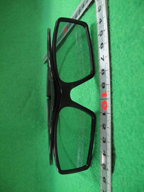
Click to zoom
Application Details
- Equipment Class
- DSS - Part 15 Spread Spectrum Transmitter
- Date of Grant
- Mar 27, 2013
- Application Purpose
- Original Equipment
- Date of Application
- Mar 26, 2013
- Equipment Note
- 3D Active Glasses
- Frequency Range
- 2402.00000000 - 2480.00000000
- Company
- Samsung Electronics Co Ltd
- Country
- United States
Documents & Files
Document Text
Text extracted from the exhibit documents filed with the FCC. Open a document above to read the original.
Users Manual
English-1 English Features Samsung's SSG-3570CR 3D glasses enable you to view 3D images on your 3D TV. The Samsung 3D glasses communicate with Samsung 3D TVs via the 2.4GHz RF band. ✎ This product can be used only with Samsung D, E, and F series 3D TVs released in 2011 to 2013 or with 3D TVs that have any of the logos below . Other wireless devices are not compatible with this product. ✎ The "Full HD 3D Glasses™" Logo signifies compatibility between display products and 3D Glasses that are compliant with the "Full HD 3D Glasses™" format and does not indicate the picture quality of the 3D images visible using the glasses, which depends on the quality of the display products. PartsComponents 3D Active Glasses User Guide Cleaning cloth Micro USB Cable Nose pad ※ To wear the 3D glasses over eyeglasses, detach the nose pad from the 3D glasses. ※ Refer to the last chapter in this user guide for details about how to attach or detach the nose pad. Pairing 3D Active Glasses ✎ What is Pairing? Pairing is a process that prepares devices to exchange data so that, in operation, the devices can transmit and exchange data instantly. ✎ Once the 3D glasses are paired, the r emaining battery capacity is displayed on the TV screen. (This feature only applies to Samsung F series 3D TVs and 3D glasses that have been launched since 2013.) ✎ The working distance depends on obstacles (a person, metal, walls, etc.) or electromagnetic waves. ✎ Note that if you take off the 3D glasses while viewing 3D video and the 3D mode remains enabled on your TV, it will take 5 minutes for the 3D glasses to power off. ✎ If the glasses do not operate immediately when you put them on while the TV is in 3D mode, put the glasses on again. ✎ This product is rechargeable. It may not operate due to the dead battery when you attempt to use it for the first time. In this case, charge the battery . 3D Active Glasses SSG-3570CR User’s Guide Pairing: Press the pairing button on the 3D glasses for more than 1 seconds. Pairing will start. Turning the glasses on and off: Put on the 3D glasses. The glasses will automatically power on and the green LED will be lit for 3 seconds. To power off the glasses, take off the glasses. Several minutes later, the glasses will automatically power off and the red LED will be lit for 3 seconds. (Make sure that 3D is activated on the TV before using the 3D glasses.) Operating range Recommended viewing distance 2~6m Recommended pairing distance 50 cm Recommended viewing distance Recommended pairing distance or Nose pad pairing button Liquid-crystal shutter 2~6m 50cm [NA]SSG-3570CR-00L17.indb 12013-01-02 9:15:09 English-2 Pairing for the first time 1. Turn on the TV and wait until the TV is fully on. 2. Press the pairing button on the 3D glasses shortly. The 3D glasses will power on and pairing will start. 3. The message “3D glasses are connected to TV.” will be displayed on the TV screen when the pairing is successfully completed. 4. Enjoy 3D video after configuring the 3D function settings on the TV. ✎ After the first pairing, putting on the 3D glasses will automatically power on the glasses. To power off, take off the glasses. ✎ If the pairing fails, the 3D glasses will power off. ✎ If the first attempt to pair fails, turn the TV off and on again, and then go to Step 2. ✎ The LED will blink green and red alter nately for 1 seconds if pairing is in progress. How to pair again: Press the pairing button on the 3D glasses for more than 1 seconds. <Pairing is needed again in the following occasions> – Pairing may be needed again after you have had your 3D TV repaired. – If you want to play 3D content on another Samsung 3D TV model that belongs to the D, E, or F series released in 2011 through 2013. Charging the Battery If the red LED blinks every 2 seconds, charge the battery as shown below. The orange LED will blink every second when battery charging is in progress. The green LED will blink every 2 seconds when the charging is finished. (It takes about 30 minutes to fully charge the battery that is dead; however, the time required to charge it to full capacity may vary depending on the battery level and the voltage of the supplied power.) USB1 USB USB PORT Micro USB Cable SAMSUNG TV PC Note Book Viewing guidelines • When viewing 3D video under a fluorescent lamp (50Hz – 60Hz) or 3-wavelength lamp, you may notice a small amount of screen flickering. ※ If so, dim the light or turn the lamp off. • Switching the input mode while watching a 3D movie may disable the 3D function on the TV. As a result, the 3D glasses may not function and the movie may not be displayed properly. • Ensure you are within the working range when you view a 3D video. ※ If you move the 3D glasses outside of their working range, the signal from the TV will be disconnected, and the 3D glasses will be automatically turned of f. When this happens, the red LED will turn on for 3 seconds. [NA]SSG-3570CR-00L17.indb 22013-01-02 9:15:09 English-3 English • The vividness of the image may appear degraded if you view 3D video in a place that is exposed to direct sunlight or illumination. • If you lie on your side while watching TV with 3D glasses, the picture may look dark or may not be visible. • The 3D effect may be experienced differently depending on the viewer. You may not notice the 3D effect at all if you have a prescription for one eye that is very different from the other eye. • If a lens or any part of the 3D glasses is defective or damaged, the glasses cannot be repaired and should be exchanged. Broken 3D glasses can be exchanged for a new pair free of charge within the warranty period. Note that damage caused by the fault of the user is not covered by the warranty. • The 3D glasses may not function properly if there are any nearby 3D products or electromagnetic devices (a microwave or a device that uses 2.4 GHz-bandwidth frequency such as an Internet router) turned on. If an unintended operation of the 3D function occurs, it …
Text truncated - open the document above for the full version.
Cover Letter(s)
129, Samsung-Ro, Yeongtong-Gu, Suwon-Si, Gyeonggi-Do, KOREA ATTESTATION SATATEMENT FCC ID : A3LSSG3570CR This Smart Touch Control contains an embedded Bluetooth device that Samsung confirms compliance with the following Part 15 regulations. 15.247(a)(1) The hopping sequence is pseudorandom All channels are used equally on average The receiver input bandwidth equals the transmit bandwidth The receiver hops in sequence with the transmit signal 15.247(g) The system is designed to comply with all of the regulations in Section 15.247 when the transmitter is presented with a continuous data (or information)stream. 15.247(h) The system does not coordinate it channels selection/hopping sequence with other frequency hopping systems for the express purpose of avoiding the simultaneous occupancy of individual hopping frequencies by multiple transmitters. Name : Sang Kyung (Peter), Ra Title : General Manager Company : Samsung Electronics Co., Ltd.
Cover Letter(s)
129, Samsung-Ro, Yeongtong-Gu, Suwon-Si, Gyeonggi-Do, KOREA Federal Communications Commission Authorization and Evaluation Division 7435 Oakland Mills Road, Columbia, MD 21046 Date: February 7, 2013 RE: Request of confidentiality for FCC ID: A3LSSG3570CR To Whom It May Concern: Pursuant to Sections 0.457 and 0.459 of the Commission’s Rules (CFR 47), and Sectio 552 (b) (4) of the Freedom of Information Act, SAMSUNG ELECTRONICS CO.,LTD. Hereby requests confidentiality and treatment of certain information accompanying this application. The materials contain trade secrets and proprietary information not customarily released to the public. The public disclosure of these matters might be harmful to the Applicant and provide unjustified benefits to its competitors. We are also hereby request Short-Term Confidentiality for 180 day after the grant as outlined in Public Notice DA 04-1705. This provision will give SAMSUNG ELECTRONICS CO.,LTD. Temporary confidentiality of commercially sensitive information prior to product release. The requested Permanent and Short-Term Confidential exhibits are listed as follows: PERMANENT AND SHORT-TERM CONFIDENTIAL LIST Exhibit Description PERMANENT 1 Block Diagram 2 Operational Description 3 Schematics SHORT-TERM 4 External Photos 5 Internal Photos 6 Test-Setup Photos 7 Users Manual The Applicant understands that pursuant to Rule 0.457, disclosure of this application and all accompanying documentations, where applicable, will not be made public before the date of the Grant for this application. Sincerely, Name : Sang Kyung (Peter), Ra Title : General Manager Company : Samsung Electronics Co., Ltd.
Cover Letter(s)
Nemko Canada Inc 303 River Road Ottawa, Ontario, Canada K1V 1H2 Attn: Director of Certification Authority to Act as Agent On our behalf, I appoint Nemko Korea Co., Ltd. (153 & 159, Osan-Ro, Mohyeon-Myeon, Cheoin-Gu, Yongin-Si, Gyeonggi-Do, 449-852 Korea, REPUBLIC OF) to act as our agent in the preparation of this application for equipment certification. I certify that submitted documents properly describe the device or system for which equipment certification is sought. I also certify that each unit manufactured, imported or marketed, as defined in the Federal Communications Commission’s regulations will have affixed to it a label identical to that submitted for approval with this application. For instances where our authorized agent signs the application for certification on our behalf, I acknowledge that all responsibility for complying with the terms and conditions for certification, as specified by Nemko Canada Inc, still resides with Samsung Electronics Co., Ltd. (129, Samsung-ro, Yeongtong-gu, Suwon-si, Gyeonggi-do, Korea, 443-742). Dated this 7 Day of February 20 13 Agency agreement expiration date: December 31, 2013 By: Sang Kyung (Peter), Ra Signature Printed Title: General Manager On behalf of : Samsung Electronics Co., Ltd. Telephone: 973-808-6362
External Photos
Test Report No.: NK-13-R-018 FCC and IC Certification Samsung Electronics Co., Ltd. FCC ID : A3LSSG3570CR / IC : 649E-SSG3570CR Page 42 of 46 APPENDIX C – EUT PHOTOGRAPHS Front View of EUT Test Report No.: NK-13-R-018 FCC and IC Certification Samsung Electronics Co., Ltd. FCC ID : A3LSSG3570CR / IC : 649E-SSG3570CR Page 43 of 46 Rear View of EUT
ID Label/Location Info
Test Report No.: NK-13-R-018 FCC and IC Certification Samsung Electronics Co., Ltd. FCC ID : A3LSSG3570CR / IC : 649E-SSG3570CR Page 40 of 46 APPENDIX A – LABELLING REQUIREMENTS The sample label shown shall be permanently affixed at a conspicuous location on the device and be readily visible to the user at the time of purchase. Labelling Requirements
Internal Photos
Test Report No.: NK-13-R-018 FCC and IC Certification Samsung Electronics Co., Ltd. FCC ID : A3LSSG3570CR / IC : 649E-SSG3570CR Page 44 of 46 Inside View of EUT Test Report No.: NK-13-R-018 FCC and IC Certification Samsung Electronics Co., Ltd. FCC ID : A3LSSG3570CR / IC : 649E-SSG3570CR Page 45 of 46 Front View of Main board Test Report No.: NK-13-R-018 FCC and IC Certification Samsung Electronics Co., Ltd. FCC ID : A3LSSG3570CR / IC : 649E-SSG3570CR Page 46 of 46 Rear View of Main board
RF Exposure Info
RF Exposure FCC ID : A3LSSG3570CR Applicable Standard According to §1.1307(b)(5), systems operating under the provisions of this section shall be operated in a manner that ensure that the public is not exposed to radio frequency energy level in excess of the Commission’s guideline. This Smart Touch Control can be used in a Portable device. KDB616217 was used as the guidance. According to §1.1310 and §2.1093 RF exposure is calculated. Measurement Result Model name Conducted output power (dBm) Conducted output power (mW) Antenna gain (dBi) Antenna gain (Numeric) *Conducted output power (EIRP) (mW) **Low threshold for general public (mW) SSG-3570 1.44 1.39 4.48 2.81 3.91 24.58 Notes: 1. *Conducted output power (EIRP) (mW) = Conducted output power(mW) x Antenna gain (Numeric) 2. **Low threshold for general public (mW) = 60/f GHz = 60/2.441 GHz Therefore, SSG-3570CR is not required the SAR Evaluation.
Test Report
Test Report No.: NK-13-R-018 FCC and IC Certification Samsung Electronics Co., Ltd. FCC ID : A3LSSG3570CR / IC : 649E-SSG3570CR Page 2 of 46 TABLE OF CONTENTS 1. Scope 4 2. Introduction (Site Description) 5 2.1 Test facility 5 2.2 Accreditation and listing 6 3. Test Conditions & EUT Information 7 3.1 Operation During Test 7 3.2 Support Equipment 7 3.3 Setup Drawing 7 3.4 EUT Information 8 4. Summary of Test Results 9 5. Recommendation / Conclusion 10 6. Antenna Requirements 10 7. Description of Test 11 7.1 Conducted Emissions 11 7.2 Radiated Emissions 12 7.3 20 dB Bandwidth and Carrier Frequency Separation 13 7.4 Transmitter Average Time of Occupancy 13 7.5 Number of Hopping Channels 14 7.6 Maximum Peak Output Power 14 7.7 Conducted Spurious Emissions 15 8. Test Data 16 8.1 Radiated Emissions 16 8.2 20 dB Modulated Bandwidth 17 8.3 Carrier Frequency Separation 20 8.4 Transmitter Average Time of Occupancy 22 Test Report No.: NK-13-R-018 FCC and IC Certification Samsung Electronics Co., Ltd. FCC ID : A3LSSG3570CR / IC : 649E-SSG3570CR Page 3 of 46 8.5 Number of Hopping Channels 24 8.6 Peak Power Output 25 8.7 Conducted Spurious Emissions 28 8.8 Radiated Spurious Emissions 34 8.9 Radiated Restricted Band Edge 36 9. Test Equipment 37 10 Accuracy of Measurement 38 Appendix A: Labeling Requirement 40 Appendix B: Photographs of Test Set-up 41 Appendix C: EUT Photographs 42 Test Report No.: NK-13-R-018 FCC and IC Certification Samsung Electronics Co., Ltd. FCC ID : A3LSSG3570CR / IC : 649E-SSG3570CR Page 4 of 46 1. SCOPE Measurement and determination of electromagnetic emissions (EME) of radio frequency devices including intentional and/or unintentional radiators for compliance with the technical rules and regulations of the Federal Communications Commission under FCC part 15 subpart C and IC RSS-210 Issue 8. Responsible Party : Contact Person : Manufacturer : Samsung Electronics Co., Ltd. Mr. Jaywoo. Lee Samsung Electronics Co., Ltd. 129, Samsung-ro, Yeongtong-gu, Suwon-si, Gyeonggi-do, Korea 443-742 FCC ID: A3LSSG3570CR Model: SSG-3570CR Brand Name: SAMSUNG EUT Type: 3D Active Glasses Classification: 15C Intentional Radiator Applied Standard: FCC 47 CFR Part 15 subpart C and IC RSS-210 Issue 8 Test Procedure(s): ANSI C63.4-2003, ANSI C63.10 and FCC Public Notice DA 00- 705 dated March 30, 2000 entitled “Filling and Measurement Guidelines for Frequency Hopping Spread Spectrum Systems” Dates of Test: January 11, 2013 ~ February 3, 2013 Place of Tests: Nemko Korea Co., Ltd. Test Report No.: NK-13-R-018 FCC and IC Certification Samsung Electronics Co., Ltd. FCC ID : A3LSSG3570CR / IC : 649E-SSG3570CR Page 5 of 46 2. INTRODUCTION 2.1 Test facility The measurement procedure described in American National Standard for Methods of Measurement of Radio-Noise Emissions from Low-Voltage Electrical and Electronic Equipment in the Range of 9 kHz to 40 GHz (ANSI C63.4-2003), the American National Standard for Testing Unlicensed Wireless Devices (ANSI C63.10-2009) were used in determining radiated and conducted emissions emanating from Samsung Electronics Co., Ltd. FCC ID : A3LSSG3570CR and IC : 649E-SSG3570CR These measurement tests were conducted at Nemko Korea Co., Ltd. EMC Laboratory. The site address is 155 & 159, Osan-Ro, Mohyeon-Myeon, Cheoin-Gu, Yongin-Si, Gyeonggi- Do, 449-852 KOREA, REPUBLIC OF. The area of Nemko Korea Corporation Ltd. EMC Test Site is located in a mountain area at 80 kilo-meters (48 miles) southeast and Incheon International Airport (Incheon Airport), 30 kilometers (18 miles) south-southeast from central Seoul. It is located in the valley surrounded by mountains in all directions where ambient radio signal conditions are quiet and a favorable area to measure the radio frequency interference on open field test site for the computing and ISM devices manufactures. The detailed description of the measurement facility was found to be in compliance with the requirements of §2.948 according to ANSI C63.4 2003. Fig. 1. The map above shows the Seoul in Korea vicinity area. The map also shows Nemko Korea Corporation Ltd. EMC Lab. and Incheon Airport. Nemko Korea Co., Ltd. EMC Lab. 155 & 159, Osan-Ro, Mohyeon- Myeon, Cheoin-Gu, Yongin-Si, Gyeonggi-Do, 449-852 KOREA, REPUBLIC OF Tel)+82-31-330-1700 Fax)+82-31-322-2332 Test Report No.: NK-13-R-018 FCC and IC Certification Samsung Electronics Co., Ltd. FCC ID : A3LSSG3570CR / IC : 649E-SSG3570CR Page 6 of 46 2.2 Accreditation and listing Accreditation type Accreditation number FCC part 15/18 Filing site Registration No. 97992 CAB Accreditation for DOC Designation No. KR0026 KOLAS Accredited Lab. (Korea Laboratory Accreditation Scheme) Registration No. 155 Canada IC Registered site Site No. 2040E VCCI registration site(RE/CE/Telecom CE) Member No. 2118 EMC CBTL - KCC(RRL)Designated Lab. Registration No. KR0026 SASO registered Lab and Certification Body Registration No. 2008-15 Test Report No.: NK-13-R-018 FCC and IC Certification Samsung Electronics Co., Ltd. FCC ID : A3LSSG3570CR / IC : 649E-SSG3570CR Page 7 of 46 3. TEST CONDITIONS & EUT INFORMATION 3.1 Operation During Test This device has two kinds of modulation methods, both FHSS and Non-FHSS. At the beginning of paring to companion device, it use FHSS mode. After connecting, it use Non-FHSS mode. The Laptop and Test Jig were used to control the EUT to transmit the wanted TX channel by the Bluetool testing program which manufacturer supported. The Laptop was removed after controlling the EUT to transmit the wanted signal. The EUT was measured at X, Y, Z-Axis in Bluetooth Traffic mode with the maximum output power in accordance with the manufacturer’s specifications. The worst data were recorded in the report. 3.2 Support Equipment 3D Active Glasses (EUT) Samsung Electronics Co., Ltd. Model: SSG-3570CR FCC ID : A3LSSG3570CR S/N: N/A Laptop Computer Samsung Electronics Co., Ltd. Model : NT-R520 0.3 m USB shielded cable FCC DOC S/N: ZK6V93FS800012Y AC/DC Adaptor for Laptop Chi…
Text truncated - open the document above for the full version.
Test Report
Reply to an OET Inquiry Response Currently Displaying Inquiry Tracking Number: 253219 Inquiry Details on 01/29/2013: First category: Mfg/Test Lab Test Guidance - Evolving Technology Second category: EMC/Radio Parameters Third category: Subject: Rule for the device using frequency hopping and non-hopping Inquiry: Dear Sir or Madam, I would like to ask your advice for the end product using 2.4 GHz band. This device has 2 kind of spreading way, both FHSS and Non- FHSS. At the beginning of paring to companion device, it use FHSS type. But after they connected this device use Non-FHSS (DTS) way Normally this device use Non-FHSS (DTS) way but FHSS at only beginning It uses Bluetooth chipset therefore it’s waveform is same to Bluetooth’s whenever it works with hopping or non-hopping. Freqeuncy band : 2402~2480 MHz Channel space : 1 MHz Modulation : GFSK only Question 1) If the operating mode is non-hopping mode, which occupied bandwidth is right 6 dB bandwidth or 20 dB bandwidth? Question 2) If the operating mode is non-hopping mode and 6 dB bandwidth is right, do I have to test it according to KBD558074 D01v02 for 6 dB bandwidth? Pre-test result : RBW <80 kHz, the measured 6 dB bandwidth < 500 kHz (Fail) RBW = 100 kHz, the measured 6 dB bandwidth > 500 kHz (Pass) I am not sure it is against the KDB 558074 d01v02 to use 100 kHz RBW for this device. Extract from KBD 558074 D01v02 : 7.0 DTS (6 dB) CHANNEL BANDWIDTH One of the following procedures can be used to determine the modulated DTS channel bandwidth: 7.1 Option 1: 1. Set resolution bandwidth (RBW) = 1-5% or DTS BW, not to exceed 100 kHz. Question 3) If this new device does not meet the 6 dB bandwidth, may it use 15.249 rule? Best regards, minchul FCC Response on 01/30/2013: In non-hopping mode, the only regulation regarding bandwidth is with regards to the 6 dB DTS bandwidth. To properly resolve all spectral components in the bandwidth test, the resolution bandwidth must be limited to a value that is between 1-5% of the emission bandwidth. Thus, for a 1 MHz emission bandwidth, the maximum RBW that can be used is 50 kHz. ---Reply from Customer on 01/31/2013--- Thanks for your response! Regarding this issue, I would like to ask your decision. Please find the attached the operational description to help your understanding. I found out the KBD 453039 handled the similar to our issue. There are three examples. I would appriciate if you judge whether it is right or wrong to use third example. If you have opinion that it is wrong to use the third example, may I use 15.249 rule instead of 15.247? Extract from KBD 453039 First example: We will allow a manufacturer of a combination DTS and FHSS system to demonstrate compliance with the rules required for DTS operation or for FHSS operation. There is no need to demonstrate compliance with both the FHSS standards and the DTS standards. Second example: Systems may employ two mutually exclusive operational modes. One mode would be as a FHSS system and the other would be as a DTS. For example, a device may be operated as a FHSS system while transmitting data and as a DTS while in the acquisition mode. When operating in this manner, the device must fully comply with the rules for a FHSS system when operating in that mode and as a DTS when operating in that mode. The two types of operation must be distinct so that each mode of operation can be distinguished and separately demonstrated to comply with the pertinent standards. Third example: The third method of authorizing a combination system is as a hybrid system under the provisions described in Section 15.247(f) of the rules. Before the new rules on DTS operation, a hybrid system consisted of a transmission system that employed a combination of both direct sequence and frequency hopping techniques. Such systems were required to show compliance with a 17 dB processing gain. This is no longer required since the processing gain requirement has been replaced by the DTS regulations. A hybrid system uses both digital modulation and frequency hopping techniques at the same time on the same carrier. This is similar to the combination DTS/FHSS system described above in the first example but the system is subject to slightly different standards. As shown in Section 15.247(f), a hybrid system must comply with the power density standard of 8 dBm in any 3 kHz band when the frequency hopping function is turned off. The transmission also must comply with a 0.4 second/channel maximum dwell time when the hopping function is turned on. There is no requirement for this type of hybrid system to comply with the 500 kHz minimum bandwidth normally associated with a DTS transmission; and, there is no minimum number of hopping channels associated with this type of hybrid system. However, the hopping function must be a true hopping system, as described in Section 15.247(a)(1). The specific requirements in Section 15.247(a)(1) are: 1) a minimum channel separation; 2) pseudo-random hop sequence; 3) equal use of each frequency; 4) receiver matching bandwidth and Synchronization; The additional requirements in Section 15.247 for a hybrid transmitter include the requirements the 1 watt output limit and RF safety requirements in Section 15.247(b) and the spurious emission limits of Section 15.247(c). Best regards, minchul FCC Response on 02/01/2013: Based on the description that you've provided, the second example from KDB 453039 appears to be applicable. If the device radiates using both FHSS and non-FHSS (DTS), compliance must be shown to each of the applicable rule parts (i.e., 15.247(a)(1) and 15.247(a)(2), respectively. Compliance measurement guidance for the FHSS portion of the device is provided in DA 00-705 and C63.10-2009. Compliance measurement guidance for the non- FHSS device emissions can be found in KDB 558074. ---Reply from Customer on 02/02/2013--- Thanks for your kind response. If this device does not meet the 6 dB bandwidth with non-hopping mode for narrow spectrum RBW…
Text truncated - open the document above for the full version.
Test Setup Photos
Test Report No.: NK-13-R-018 FCC and IC Certification Samsung Electronics Co., Ltd. FCC ID : A3LSSG3570CR / IC : 649E-SSG3570CR Page 41 of 46 APPENDIX B – PHOTOGRAPHS OF TEST SET-UP The Radiated Test Picture and show the worst-case configuration and cable placement. •Radiated emission test picture (front) •Radiated emission test picture (Rear)
Contact Information
Applicant
Jenni Chun(General Manager)
Technical Contact
Nemko Korea Co.,Ltd.Jaywoo Lee
[email protected]+82-31-277-2569
129, Samsung-ro, Yeongtong-gu · Suwon · South Korea
Test Firm
Nemko Korea Co.,Ltd.Hyun-ho Kim
Technical Specifications
| # | Rule Parts | Frequency Range | Power Output |
|---|---|---|---|
| 1 | 15C | 2.40 GHz - 2.48 GHz | 1.00 mW |
Other Applications from Samsung Electronics Co Ltd
A3LSMS741B
Aug 05, 2026Portable Handset
Equipment Class
6VL - 15E 6 GHZ Very Low Power DeviceA3LSMX940
Jul 31, 2026BT,BLE Tablet DTS,UNII a,b,g,n,ac,ax,be and digitizer
Equipment Class
DTS - Digital Transmission SystemA3LSMS741U
Jul 30, 2026Portable Handset
Equipment Class
6CD - 15E 6 GHz Low Power Dual ClientA3LSMX840
Jul 27, 2026BT,BLE Tablet DTS,UNII a,b,g,n,ac,ax and Digitizer
Equipment Class
DSS - Part 15 Spread Spectrum TransmitterA3LSMX848U
Jul 27, 2026WCDMA, LTE, 5G NR Tablet BT,BLE, DTS,UNII a b g n ac ax and Digitizer
Equipment Class
JBP - Part 15 Class B Computing Device Peripheral