A3LSWA4000Wireless Receiver Module
Samsung Electronics Co Ltd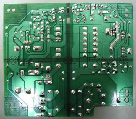
Click to zoom
Application Details
- Equipment Class
- DTS - Digital Transmission System
- Date of Grant
- Mar 14, 2008
- Application Purpose
- Original Equipment
- Date of Application
- Mar 14, 2008
- Equipment Note
- Wireless Receiver Module
- Frequency Range
- 5745.00000000 - 5805.00000000
- Company
- Samsung Electronics Co Ltd
- Country
- United States
Documents & Files
Document Text
Text extracted from the exhibit documents filed with the FCC. Open a document above to read the original.
Users Manual
DIGITAL HOME THEATER SYSTEMSWA-4000 Instruction Manual AH68-01713R V I D E O COMPACT DIGITAL AUDIO SAMSUNG ELECTRONICS AMERICA, INC. SERVICE DIVISION 400 Valley Road, Suite 201 Mount Arlington, NJ 07856 1-800-SAMSUNG (1-800-726-7864) www.samsung.com EN G 12 Safety Warnings Precautions Ensure that the AC power supply in your house complies with the identification sticker located on the back of your player. Inst all your player horizontally, on a suitable base (furniture), with enough space around it for ventilation (3~4inches). Make sure the ven tilation slots are not covered. Do not stack anything on top of the player. Do not place the player on amplifiers or other equipment whi ch may become hot. Before moving the player, ensure the disc tray is empty. This player is designed for continuous use. Switching off the Home Theater to the stand-by mode does not disconnect the electrical supply. In order to disconnect the player completely from the power Protect the player from moisture(i.e. vases) , and excess heat(e.g.fireplace) or equipment creating strong magnetic or electric fields(i.e.speakers...). Disconnect the power cable from the AC supply if theplayer malfunctions. Your player is not intended for industrial use.Use of this product is for personal use only.Condensation may occur if your player or disc has been stored in coldtemperatures.If transporting the player during the winter, wait approximately 2 hoursuntil the unit has reached room temperature before using. Phones During thunderstorms, disconnect AC main plug from thewall outlet.Voltage peaks due to lightning could damage the unit. Do not expose the unit to direct sunlight or other heatsources.This could lead to overheating and malfunction of the unit. The batteries used with this product contain chemicalsthat are harmful to the environment. Do not dispose of batteries in the general householdtrash. PREPARATION CLASS 1 LASER PRODUCTThis Compact Disc player is classified as a CLASS 1LASER product.Use of controls, adjustments or performance of procedures other than those specified herein may resultin hazardous radiation exposure. CAUTION-INVISIBLE LASER RADIATION WHEN OPEN AND INTERLOCKS DEFEATED, AVOID EXPOSURE TO BEAM. This symbol indicates that dangerous voltage which can cause electric shock is present insidethis unit.This symbol alerts you to important operating and maintenance instructions accompanying the unit. WARNING: To reduce the risk of fire or electric shock, do not expose this appliance to rain or moisture. CAUTION: TO PREVENT ELECTRIC SHOCK, MATCH WIDE BLADE OF PLUG TO WIDE SLOT, FULLY INSERT. CLASS 1 LASER PRODUCTKLASSE 1 LASER PRODUKTLUOKAN 1 LASER LAITEKLASS 1 LASER APPARATPRODUCTO LASER CLASE 1 RISK OF ELECTRIC SHOCK. DO NOT OPEN CAUTION:TO REDUCE THE RISK OF ELECTRICSHOCK, DO NOT REMOVE REAR COVER.NO USER SERVICEABLE PARTS INSIDE.REFER SERVICING TO QUALIFIED SERVICE PERSONNEL. CAUTION Note to CATV system installer :This reminder is provided to call the CATV systeminstaller’s attention to Section 820~40 of the NECwhich provides guidelines for proper grounding and,in particular, specifies that the cable ground shall beconnected to the grounding system of the building,as close to the point of cable entry as practical EN G 4 3 READ INSTRUCTIONSAll the safety and operating instructions should beread before the appliance is operated.RETAIN INSTRUCTIONSThe safety and operating instructions should beretained for future reference.HEED WARNINGSAll warnings on the appliance and in the operatinginstructions should be adhered to.FOLLOW INSTRUCTIONSAll operating and use instructions should be followed.WATER AND MOISTUREDo not use this video product near water-for example, near a bathtub, wash bowl,kitchen sink, or laundry tub, in a wet basement, or near a swimming pool, and the like.OVERLOADINGDo not overload wall outlets and extension cords asthis can result in the risk of fire or electric shock.VENTILATIONSlots and openings in the cabinet are provided for ventilation and to ensure reliable operation of thevideo product and to protect it from overheatingthese openings must not be blocked or covered.The openings should never be blocked by placing the video product on a bed, sofa, rug, orother similar surface. This video product should never be placed near or over a radiator orheat register.This video product should not be placed in a built-in installation such as a bookcase or rack unless proper ventilation is provided or the manufacturer's instructions have been fol-lowed.POWER CORD PROTECTIONPower-supply cords should be routed so thatthey are not likely to be walked on or pinchedby items placed upon or against them payingparticular attention to cords at plugs,convenience receptacles, and the point wherethey exit from the appliance. CLEANINGUnplug this video product from the wall outletbefore cleaning. Do not use liquid cleaners or aerosol cleaners. Use a damp cloth for cleaning.LIGHTNINGFor added protection of this video productreceiver during a lightning storm, or when it is left unattended and unused for long periods of time, unplug it from the wall outletand disconnect the antenna or cable system. This will prevent damage to the video product due to lightning and power-line surges.OBJECT AND LIQUID ENTRYNever push objects of any kind into this product through openings as they may touchdangerous voltage points or short-out partsthat could result in a fire or electric shock.Never spill liquid of any kind on the videoproduct.ACCESSORIESDo not place this video product on an unstable cart,stand, tripod, bracket, or table. The video product may fall, causing serious injury toa child or adult, and serious damage to the appliance.Use only with a cart, stand, tripod, bracket, or table recommended by the manufacturer, or sold with the video product. Any mounting of the appliance should follow the manufacturer'sinstructions and should use a mounting accessoryrecommended by the manufacturer.CARTAn appliance and cart combination s…
Text truncated - open the document above for the full version.
Users Manual
EN G 50 SETUP 2 1 3 In Stop mode,press MENU button. Press Cursorbutton to move to‘Setup’ and thenpress ENTER button. Press Cursorbutton to move to‘LOGO’ and thenpress ENTER button. To select one of the 3 wallpaper settings you've made 5 4 Press MENU button to exit thesetup screen. Press to selectthe desired ‘USER’,and then pressENTER . Press RETURN button to return to the previous level. Press MENU button to exit the setup screen. 49 DVD JPEG Select this to set theSamsung Logo image asyour wallpaper. Select this to set the desiredimage as your wallpaper. • “ COPY LOGO DATA ” will be displayed on the TV screen. • The selected wallpaper will bedisplayed. • You can select up to 3 wallpapersettings. 2 13 During playback, pressPLAY/PAUSE button when an image youlike appears. Press LOGO button. The power willturn off and thenback on. PAUSE COPY LOGO DATA Setting the Wallpaper While watching a DVD or JPEG CD, you can set the image you like as background wallpaper. Setting the Wallpaper EN G 52 SETUP 2 1 4 3 In Stop mode,press MENU button. Press Cursorbutton to move to‘Audio’ and thenpress ENTER button. In the SpeakerSetup, press theENTER button again. Press Cursor , , , buttons to move to the desiredspeaker and thenpress ENTER button. • For C, LS, and RS, each time the buttonis pressed, the mode switchesalternately as follows: SMALL ➝ NONE. • For L and R, the mode is set to SMALL. 51 SMALL : Select this when using the speakers. NONE : Select this when no speakers are connected. • • Depending on PRO LOGIC and STEREO settings, the speaker mode may vary (see page 61). Note Signal outputs and frequency responses from the speakers will automatically be adjusted according to yourspeaker configuration and whether certain speakers are used or not. Setting the Speaker Mode 2 1 Press the MENU button while thedisc tray is open. Press Cursorbutton to move to‘Setup’ and thenpress ENTER button. 4 3 Press Cursorbutton to move to‘DVD TYPE’ and thenpress ENTER button. Press Cursor ,button to move to‘DVD VIDEO’ and thenpress ENTER button. • DVD Play mode is set to DVD Audio as factory default setting. Note • Set steps 1 ~ 4 again if you want toswitch to DVD AUDIO Play mode. When Selecting DVD Play Mode:• DVD VIDEO : set to play the DVD video contents contained on aDVD audio disc. • DVD AUDIO : set to play the default DVD audio. Some DVD-Audio discs contain DVD-Video as well as DVD-Audio.To play back the DVD-Video portion of the DVD-Audio disc, set the unit to DVD-Video mode. DVD Audio Disc Playback Mode • Please use the Registration code to register this player with the DivX (R) video on demand format. To learn more, go to www.divx.com/vod. DivX (R) registration 53 Setting up the Speaker Delay Time When 5.1CH Surround Sound is played, you can enjoy the best sound ifthe distance between you and each speaker is the same. Since the soundsarrive at the listening position at different times depending on theplacement of speakers, you can adjust this difference by adding a delayeffect to the sound of the Center Speaker and Surround Speakers. 2 1 In Stop mode,press MENU button. Press Cursor buttonto move to ‘Audio’ andthen press ENTER button. • With (Dolby Pro Logic II), the delay time may be different for each mode. • With AC-3 and DTS, the delay time can be set between 00 and 15mSEC. • The Center channel is only adjustable on 5.1 channel discs. Note If the speakers cannot be placed at equal distances from the listening position, you can adjust the delay time ofthe audio signals from the center and rear speakers. Setting the Delay Time EN G 54 Df: The distance from FRONT SPEAKERDc: The distance from CENTER SPEAKERDs: The distance from SURROUND SPEAKER Ideal CENTERSPEAKER placement It is desirable to place all speakers within this circle. IdealSURROUNDSPEAKERplacement SETUP • You can set the delay time for Cbetween 00 and 05mSEC and forLS and RS between 00 and15mSEC. 4 3 5 Press Cursor buttonto move to ‘DELAYTIME’ and then pressENTER button. Press Cursor , , , buttons to move to the desired speakerand then pressENTER button. Press Cursor ,to set the Delaytime. 0 ms3 ms 6 ms9 ms 12 ms15 ms • Setting REAR (SURROUND) SPEAKERSIf the distance of Df is equal to the distance of Dsin the figure, set the mode as 0ms. Otherwise,change the setting according to the table. • Setting CENTER SPEAKERIf the distance of Dc is equal to or longer than thedistance of Df in the figure, set the mode as 0ms.Otherwise, change the setting according to the table. Distance between Df and Dc Delay Time Delay Time 0 ms1 ms 2 ms3 ms4 ms5 ms Distance between Df and Ds 0 inch 13.6 inches27.2 inches 40.8 inches 4.5 feet 5.6 feet 0 inch 40.8 inches 6.7 feet 10.0 feet 13.4 feet 16.7 feet L: Front Speaker (L) C: Center Speaker SW: Subwoofer R: Front Speaker (R) LS: Rear Speaker (L) RS: Rear Speaker (R) Press RETURN button to return to the previous level. Press MENU button to exit the setup screen. 21 In Stop or nodisc mode,press MENU button. Press Cursorbutton to move to‘Audio’ and thenpress ENTER button. 3 Press Cursor buttonto move to ‘TESTTONE’ and then pressENTER button. • The test tone will be sent to L ➝ C ➝ R ➝ SR ➝ SL ➝ SW in order. If the ENTER button is pressed againat this time, the test tone will stop. To end the test tone, press TEST TONE button again. Press TEST TONE button. • Test tone will be produced as follows:When playing a DVD or CD, this will work only in Stop mode. • Use this function to check that each speaker iscorrectly connected and that there is no problem. Alternate method: press the TEST TONE button on the remote. Multi-Channel Pro Logic Mode Start Use the Test Tone feature to check the speaker connections. Setting the Test Tone EN G 56 55 12 In Stop or no disc mode, press MENU button. Press Cursor button tomove to ‘Audio’ and thenpress ENTER button. • When the Cursor button is pressed, the effect is greater,and when the Cursor button is pressed, the effect issmaller. 34 Press Cursor button tomove to ‘DRC’ and thenpress ENTER b…
Text truncated - open the document above for the full version.
Cover Letter(s)
Date: Mar. 4, 2008 Federal Communications Commission 7435 Oakland Mills Road Columbia MD 21046 c.c. Compliance Certification Services Certification Division 47173 Benicia Street Fremont, CA 94538, USA To whom it may concern: I, the undersigned, hereby authorize Lab Manager Jim. Kim and of SGS Testing Korea Co., Ltd and hereafter referred to as SGS Testing Korea, to act on our behalf in all manners relating to application for equipment authorization, including signing of all documents relating to these matters. Any and all acts carried out by Lab Manager Jim. Kim of SGS Testing Korea Co., Ltd on our behalf shall have the same effect as acts of our own. I, the undersigned, hereby certify that we are not subject to a denial of federal benefits, that includes FCC benefits, pursuant to Section 5301 of the Anti-Drug Abuse Act of 1988, 21 U.S.C. 853(a). In authorizing SGS Testing Korea as our agent, we still recognize that we are responsible to: a) comply with the relevant provisions of the certification program; b) make all necessary arrangements for the conduct of the evaluation, including provision for examining documentation and access to all areas, records (including internal audit reports) and personnel for the purposes of evaluation (e.g. testing, inspection, assessment, surveillance, reassessment) and resolution of complaints; c) make claims regarding certification only in respect of the scope for which certification has been granted; d) do not use our product certification in such a manner as to bring the Certification Division into disrepute and not make any statement regarding our product certification which the Certification Division may consider misleading or unauthorized; e) upon suspension or cancellation of certification, discontinue use of all advertising matter that contains any reference thereto and return any certification documents as required by the Certification Division; f) use certification only to indicate the products are certified as being in conformity with specified standards; g) endeavor to ensure that no certificate or report nor any part thereof is used in a misleading manner; h) ensure that any reference to our product certification in communication media such as documents, brochures or advertising, complies with the requirements of the Certification Division; i) keep a record of all complaints made known to the us relating to the product’s compliance with requirements of the relevant standard and to make these records available to the Certification Division when requested; j) take appropriate action with respect to such complaints and any deficiencies found in products or services that affect compliance with the requirements for certification; k) document the actions taken. This authorization is valid until further written notice from the applicant. Sincerely Yours, Steve Kim / General Manager Samsung Electronics Co., Ltd. REMARK: 1. This authorization letter will be sent along with your application when filing with the Certification Division. 2. Please follow the format and type it on company letterhead and send original to us. 3. Authorized signature must be in agreement with grantee code contact in FCC database.
Cover Letter(s)
If you have not received all pages, please call the direct phone number. FAX : 031-428-5859 TEL : 031-428-5886 Federal Communications Commission 7435 Oakland Mills Road Columbia, MD 21046 Gentlemen: This letter is to comply with Section 0.457(d)(2)(i) and 0.459 pertaining to confidential material. We, Samsung Electronics , would like the following documents regarding this submission for FCC ID: A3LSWA4000 to be kept confidential. 1. Schematics and Block diagram 2. Parts List 3. Operating description The above material contains trade secrets or technical data, which would customarily be guarded from competitors. We do not want these documents to be accessible to the general public. Sincerely, Steve. Kim / General Manager Samsung Electronics Co., Ltd.
Cover Letter(s)
1 Lucy Tsai From:Jo, Jenny (Gunpo) [[email protected]] Sent:Tuesday, March 11, 2008 1:40 AM To:Lucy Tsai; Ham, Denny (Gunpo) Cc:Kim, Raymond (Gunpo); Jeong, Feel (Gunpo); Ham, Denny (Gunpo); Kim, Tim (Gunpo) Subject:RE: SAMSUNG ELECTRONICS CO. LTD., FCC ID: A3LSWA4000, Assessment NO.: AN08T7672, Notice#1 Attachments:FCC Apply-2nd_SWA-4000(SWA-4000P).zip Dear Lucy Please find updated FCC application documents. * Attachment - FCC Label for SWA-4000 - FCC Label for SWA-4000P - Agent authorization letter (signed by Steve. Kim) - Confidentiality request Letter (signed by Steve. Kim) - Amended Test Report - User Manual (updated) - Block Diagram (updated) And please see the comment in blue as below. Many thanks, Jenny Jo / ??? SGS Testing Korea Co., Ltd. -----Original Message----- From: Lucy Tsai [mailto:[email protected]] Sent: Wednesday, March 05, 2008 6:31 PM To: Ham, Denny (Gunpo); Jo, Jenny (Gunpo) Subject: FW: SAMSUNG ELECTRONICS CO. LTD., FCC ID: A3LSWA4000, Assessment NO.: AN08T7672, Notice#1 Hi Denny, Please address following issues. Q#1: According to KDB 852143 Authorized Individual Policy (Form 731), 2 only the person who is listed as the grantee contact person on FCC website can sign the agent authorization letter. As for Samsung Electronics Co Ltd, the grantee code contact person is Steve Kim, General Manager. Please provide an authorization letter sign by him or update the grantee contact person from FCC website. Besides, please also provide the confidentiality request letter signed by Steve Kim or by his authorized agent. Attached is the new format of authorization for your reference. SGS can help Samsung to sign other doucments, for example, confidentiality request letter once you're authorized by Mr. Steve Kim. ‡ Please see the attachment. Q#2: EUT dimension is large enough that per 15.19, that following statement shall be added on the product label or a separate label is acceptable. ‡ Please see the attached new label format. This device complies with Part 15 of the FCC Rules. Operation is subject to the following two conditions: (1) this device may not cause harmful interference, and (2) this device must accept any interference Received, including interference that may cause undesired operation. Q#3: Please provide an updated user manual to include 15.21, 15.105 and RF exposure statement per 2.1091. --> Updated user manual’s attached. Q#4: Please update the block diagram to show the frequency of oscillator on it. Q#5: Please provide the difference betwee two models. ‡ Indicated on page 3. Q#6: Please correct test report page 34, the 99% BW test plot for high channel. The one shown is for middle channel but not high channel. ‡ Corrected on page 34. Best Regards, Lucy Tsai Technical Review Engineer Compliance Certification Services 47173 Benicia Street Fremont, CA 94538 Cell phone: 886-910-133-235 Direct: (510) 771-1131 Fax: (510) 661-0888 Main: (510) 771-1000 Web Site and TCB Electronic Filing System :http://www.ccsemc.com The items indicated above must be submitted before processing can continue on the above referenced application. Failure to provide the 3 requested information within 30 days of the original e-mail date may result in application dismissal and forfeiture of the filing fee. Also, please note that partial responses increase processing time and should not be submitted. Any questions about the content of this correspondence should be directed to the e-mail address listed below the name of the sender. Information in this email and any attachments is confidential and intended solely for the use of the individual(s) to whom it is addressed or otherwise directed. Please note that any views or opinions presented in this email are solely those of the author and do not necessarily represent those of the Company. Finally, the recipient should check this email and any attachments for the presence of viruses. The Company accepts no liability for any damage caused by any virus transmitted by this email. All SGS services are rendered in accordance with the applicable SGS conditions of service available on request and accessible at http://www.sgs.com/terms_and_conditions.htm
External Photos
FCC ID : A3LSWA4000 Report File No. : F690501/RF-RTL001452 Page : 46 of 52 The results shown in this test report refer only to the sample(s) tested unless otherwise stated. This test report cannot be reproduced, except in full, without prior written permission of the Company. SGS Testing Korea Co., Ltd. 18-34, Sanbon-dong, Gunpo-si, Gyeonggi-do, Korea, 435-040 Tel. +82 31 428 5700 / Fax. +82 31 427 2371 www.electrolab.kr.sgs.com Appendix B. Photos of the EUT Front View of EUT Rear View of EUT FCC ID : A3LSWA4000 Report File No. : F690501/RF-RTL001452 Page : 47 of 52 The results shown in this test report refer only to the sample(s) tested unless otherwise stated. This test report cannot be reproduced, except in full, without prior written permission of the Company. SGS Testing Korea Co., Ltd. 18-34, Sanbon-dong, Gunpo-si, Gyeonggi-do, Korea, 435-040 Tel. +82 31 428 5700 / Fax. +82 31 427 2371 www.electrolab.kr.sgs.com Right View of EUT Left View of EUT
ID Label/Location Info
FCC/IC ID LABEL 1. FCC/IC ID label drawing
Internal Photos
FCC ID : A3LSWA4000 Report File No. : F690501/RF-RTL001452 Page : 48 of 52 The results shown in this test report refer only to the sample(s) tested unless otherwise stated. This test report cannot be reproduced, except in full, without prior written permission of the Company. SGS Testing Korea Co., Ltd. 18-34, Sanbon-dong, Gunpo-si, Gyeonggi-do, Korea, 435-040 Tel. +82 31 428 5700 / Fax. +82 31 427 2371 www.electrolab.kr.sgs.com Inner of EUT Top View of PCB-Digital AMP FCC ID : A3LSWA4000 Report File No. : F690501/RF-RTL001452 Page : 49 of 52 The results shown in this test report refer only to the sample(s) tested unless otherwise stated. This test report cannot be reproduced, except in full, without prior written permission of the Company. SGS Testing Korea Co., Ltd. 18-34, Sanbon-dong, Gunpo-si, Gyeonggi-do, Korea, 435-040 Tel. +82 31 428 5700 / Fax. +82 31 427 2371 www.electrolab.kr.sgs.com Bottom View of PCB-Digital AMP Top View of PCB-SMPS FCC ID : A3LSWA4000 Report File No. : F690501/RF-RTL001452 Page : 50 of 52 The results shown in this test report refer only to the sample(s) tested unless otherwise stated. This test report cannot be reproduced, except in full, without prior written permission of the Company. SGS Testing Korea Co., Ltd. 18-34, Sanbon-dong, Gunpo-si, Gyeonggi-do, Korea, 435-040 Tel. +82 31 428 5700 / Fax. +82 31 427 2371 www.electrolab.kr.sgs.com Bottom View of PCB-SMPS Top View of RF Module FCC ID : A3LSWA4000 Report File No. : F690501/RF-RTL001452 Page : 51 of 52 The results shown in this test report refer only to the sample(s) tested unless otherwise stated. This test report cannot be reproduced, except in full, without prior written permission of the Company. SGS Testing Korea Co., Ltd. 18-34, Sanbon-dong, Gunpo-si, Gyeonggi-do, Korea, 435-040 Tel. +82 31 428 5700 / Fax. +82 31 427 2371 www.electrolab.kr.sgs.com Top View of RF Module (Removal Shield Cap) Bottom View of RF Module FCC ID : A3LSWA4000 Report File No. : F690501/RF-RTL001452 Page : 52 of 52 The results shown in this test report refer only to the sample(s) tested unless otherwise stated. This test report cannot be reproduced, except in full, without prior written permission of the Company. SGS Testing Korea Co., Ltd. 18-34, Sanbon-dong, Gunpo-si, Gyeonggi-do, Korea, 435-040 Tel. +82 31 428 5700 / Fax. +82 31 427 2371 www.electrolab.kr.sgs.com View of Antenna
RF Exposure Info
FCC ID : A3LSWA4000 Report File No. : F690501/RF-RTL001452 Page : 42 of 52 The results shown in this test report refer only to the sample(s) tested unless otherwise stated. This test report cannot be reproduced, except in full, without prior written permission of the Company. SGS Testing Korea Co., Ltd. 18-34, Sanbon-dong, Gunpo-si, Gyeonggi-do, Korea, 435-040 Tel. +82 31 428 5700 / Fax. +82 31 427 2371 www.electrolab.kr.sgs.com 10. RF Exposure Evaluation According to FCC 1.1310 : The criteria listed in the following table shall be used to evaluate the environment impact of human exposure to radio frequency (RF) radiation as specified in § 1.1307(b) LIMITS FOR MAXIMUM PERMISSIBLE EXPOSURE (MPE) 10.1 Friis transmission formula : Pd = (Pout*G)/(4*pi*R 2 ) Where Pd = power density in mW/cm 2 Pout = output power to antenna in mW G = gain of antenna in linear scale Pi = 3.1416 R = distance between observation point and center of the radiator in cm Pd the limit of MPE, 1 mW/cm 2 . If we know the maximum gain of the antenna and the total power input to the antenna, through the calculation, we will know the distance where the MPE limit is reached. Frequency Range (MHz) Electric Field Strength(V/m) Magnetic Field Strength (A/m) Power Density (mW/cm 2 ) Average Time (A) Limits for Occupational /Control Exposures 300 – 1500 -- -- F/300 6 1500 - 100000 -- -- 5 6 (B) Limits for General Population/Uncontrol Exposures 300 – 1500 -- -- F/1500 6 1500 - 100000 -- -- 1 30 FCC ID : A3LSWA4000 Report File No. : F690501/RF-RTL001452 Page : 43 of 52 The results shown in this test report refer only to the sample(s) tested unless otherwise stated. This test report cannot be reproduced, except in full, without prior written permission of the Company. SGS Testing Korea Co., Ltd. 18-34, Sanbon-dong, Gunpo-si, Gyeonggi-do, Korea, 435-040 Tel. +82 31 428 5700 / Fax. +82 31 427 2371 www.electrolab.kr.sgs.com 10.1 Test Result of RF Exposure Evaluation Test Item RF Exposure Evaluation Data Test Mode Normal Operation 10.1.1 Output Power into Antenna & RF Exposure Evaluation Distance Operating Mode: DSSS Channel Channel Frequency (MHz) Output Peak Power to Antenna (dBm) Antenna Gain (dBi) Power Density at 20cm (mW/cm 2 ) Limits (mW/cm 2 ) Low 5745 14.86 -1.87 0.00396 1 Middle 5785 13.44 -1.87 0.00286 1 High 5805 12.74 -1.87 0.00243 1
Test Report
FCC ID : A3LSWA4000 Report File No. : F690501/RF-RTL001452 Page : 1 of 52 The results shown in this test report refer only to the sample(s) tested unless otherwise stated. This test report cannot be reproduced, except in full, without prior written permission of the Company. SGS Testing Korea Co., Ltd. 18-34, Sanbon-dong, Gunpo-si, Gyeonggi-do, Korea, 435-040 Tel. +82 31 428 5700 / Fax. +82 31 427 2371 www.electrolab.kr.sgs.com TEST REPORT OF FCC Part 15 Subpart B&C §15.247/RSS-210 Issue 7, RSS-Gen Issue 2 FCC ID/IC Certification: A3LSWA4000/639E-SWA4000 Equipment Under Test :Wireless Receiver Module Model Name : SWA-4000(addition of model number:SWA-4000P) Serial No. :N/A Applicant :SAMSUNG ELECTRONICS CO.,LTD. Manufacturer : SAMSUNG ELECTRONICS HUIZHOU CO.,LTD. Date of Test(s) :2008-01-10 ~ 2008-02-20 Date of Issue :2008-03-03 In the configuration tested, the EUT complied with the standards specified above. Te s t e d B y : Date 2008-03-03 Feel Jeong Approved By Date 2008-03-03 Denny Ham FCC ID : A3LSWA4000 Report File No. : F690501/RF-RTL001452 Page : 2 of 52 The results shown in this test report refer only to the sample(s) tested unless otherwise stated. This test report cannot be reproduced, except in full, without prior written permission of the Company. SGS Testing Korea Co., Ltd. 18-34, Sanbon-dong, Gunpo-si, Gyeonggi-do, Korea, 435-040 Tel. +82 31 428 5700 / Fax. +82 31 427 2371 www.electrolab.kr.sgs.com INDEX TABLE OF CONTENTS Page 1. General Information ----------------------------------------------------------------------- 3 2. Transmitter AC Power Line Conducted Emission----------------------------------- 6 3. Receiver AC Power Line Conducted Emission---------------------------------------- 11 4. Transmitter Radiated Spurious Emissions and Conducted Spurious Emission--------- 15 5. Receiver Radiated Spurious Emission-------------------------------------------------- 27 6. 6 dB Bandwidth and 99 % BW---------------------------------------------------------- 29 7. Maximum Peak Output Power ---------------------------------------------------------- 35 8. Power Spectral Density ------------------------------------------------------------------- 38 9. Antenna Requirement -------------------------------------------------------------------- 41 10.RF Exposure Evaluation ----------------------------------------------------------------- 42 Appendix A-1. Photo of Spurious Emission Test Appendix A -2. Photos of Conducted Power Line Test Appendix B. Photos of the EUT FCC ID : A3LSWA4000 Report File No. : F690501/RF-RTL001452 Page : 3 of 52 The results shown in this test report refer only to the sample(s) tested unless otherwise stated. This test report cannot be reproduced, except in full, without prior written permission of the Company. SGS Testing Korea Co., Ltd. 18-34, Sanbon-dong, Gunpo-si, Gyeonggi-do, Korea, 435-040 Tel. +82 31 428 5700 / Fax. +82 31 427 2371 www.electrolab.kr.sgs.com 1. General Information 1.1. Testing Laboratory SGS Testing Korea Co., Ltd. -Wireless Div. 2FL, 18-34, Sanbon-dong, Gunpo-si, Gyeonggi-do, Korea 435-040 - 705, Dongchun-Dong Sooji-Gu, Yongin-Shi, Kyungki-Do, South Korea . www.electrolab.kr.sgs.com Telephone : +82 +31 428 5700 FAX : +82 +31 427 2371 1.2. Details of Applicant Applicant : SAMSUNG ELECTRONICS CO.,LTD. Address : 416, Maetan-dong, Yeongtong-gu, Suwon-si, Gyeonggi-do, Korea Contact Person : O-Won, Seo Phone No. : 82-31-227-6775 Fax No. : - 1.3. Description of EUT Kind of Product Wireless Receiver Module Model Name SWA-4000(addition of model number:SWA-4000P) Serial Number N/A Power Supply AC 120 V Frequency Range 5745 ~ 5805 MHz Modulation Technique DSSS Number of Channels 4 Operating Conditions 5 ~ 35 Antenna Type FIFA Type Antenna Gain -1.87 dBi * SWA-4000P : It is exact same as SWA-4000, but it is the marketing name as PAVV. 1.4. Details of modification -N/A FCC ID : A3LSWA4000 Report File No. : F690501/RF-RTL001452 Page : 4 of 52 The results shown in this test report refer only to the sample(s) tested unless otherwise stated. This test report cannot be reproduced, except in full, without prior written permission of the…
Text truncated - open the document above for the full version.
Contact Information
Applicant
Jenni Chun(General Manager)
Test Firm
SGS Korea Co., Ltd.Julia Choi
Technical Specifications
| # | Rule Parts | Frequency Range | Power Output |
|---|---|---|---|
| 1 | 15C | 5.75 GHz - 5.80 GHz | 31.00 mW |
Other Applications from Samsung Electronics Co Ltd
A3LSMS741B
Aug 05, 2026Portable Handset
Equipment Class
6VL - 15E 6 GHZ Very Low Power DeviceA3LSMX940
Jul 31, 2026BT,BLE Tablet DTS,UNII a,b,g,n,ac,ax,be and digitizer
Equipment Class
DTS - Digital Transmission SystemA3LSMS741U
Jul 30, 2026Portable Handset
Equipment Class
6CD - 15E 6 GHz Low Power Dual ClientA3LSMX840
Jul 27, 2026BT,BLE Tablet DTS,UNII a,b,g,n,ac,ax and Digitizer
Equipment Class
DSS - Part 15 Spread Spectrum TransmitterA3LSMX848U
Jul 27, 2026WCDMA, LTE, 5G NR Tablet BT,BLE, DTS,UNII a b g n ac ax and Digitizer
Equipment Class
JBP - Part 15 Class B Computing Device Peripheral