A3LSX10Notebook PC
Samsung Electronics Co Ltd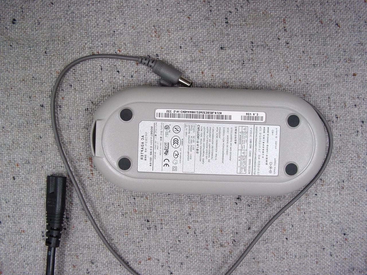
Click to zoom
Application Details
- Equipment Class
- JBC - Part 15 Class B Computing Device/Personal Computer
- Date of Grant
- Apr 10, 2003
- Application Purpose
- Original Equipment
- Date of Application
- Apr 10, 2003
- Equipment Note
- Notebook PC
- Company
- Samsung Electronics Co Ltd
- Country
- United States
Documents & Files
Document Text
Text extracted from the exhibit documents filed with the FCC. Open a document above to read the original.
Users Manual
54 Users Manual Starting System Setup To start System Setup, turn on your computer and then press <F2> and hold until the System Setup screen appears. Table 3. System Setup Menus To open the menu you need to use, use the left or right arrow keys to select the menu name. Table 4. System Setup Navigation Keys MenuFunction MainChanges the basic system. AdvancedConfigures advanced features on your computer. SecurityEnables security features, including passwords. BootSpecifies the order of boot devices and configures boot features. ExitSpecifies how to exit System Setup. Navigation KeyFunction <F1>Displays the General Help window. <Esc>Exits the current menu. <Up Arrow> or <Down Arrow> Moves the cursor up and down between fields. <Left Arrow> or <Right Arrow> Selects different menus. Pressing the <Esc>key at the Main menu brings you to the Exit menu. <F5>Scrolls backwards through the options for the highlighted field. <F6>Scrolls forward through the options for the highlighted field. <F9>Sets the parameters for the current menu to their default values. <F10>Save changes and exit system setup. <Enter>Executes commands or opens a submenu. Customizing Your Computer 55 Changing Booting Priority The Boot menu in System Setup enables you to select the booting device and to set booting options. Boot Device Priority field enables: You to select the order in which the computer attempts to boot from different devices. The field has four (4) options: CD-ROM Drive, Removable Devices, Hard Drive and MBA UNDI (Bus2 Slot5). To change the booting device priority, choose the device positions by completing the following: 1.At startup, press <F2> to open System Setup. 2.Use<Right Arrow> to select the Boot menu. 3.Press <Enter> to enter Boot Options. 4.Highlight the 1 stBoot Device option with <Up Arrow> or <Down Arrow> keys. 5.Press <F6>key until the option moves up in the list to the desired position orpress <F5> key until the option moves down in the list to the desired position. 6.Press <F10> to exit and save your changes. 7.Press <Enter> again to restart the computer. 56 Users Manual Configuring the Password Setting the Supervisor Password By configuring a supervisor password, you can restrict system access to authorized users only. 1.Select the Security menu in the System Setup. To enter System Setup, see “Starting System Setup” on page 54. 2.On the Set Supervisor Password item, press <Enter>. 3.Enter a password, press <Enter>, re-enter the password for confirmation, and press<Enter> again. 4.When a message confirming the password configuration appears in the [Setup Notice] window, press <Enter>. Setting the User Password You can configure user passwords so that other users can use the system. Before configuring a user password, a supervisor password must have been configured. Users can start the system with their user password, but cannot enter into the System Setup. Deactivating the supervisor password also deactivates the user password. On the Set User Password item, press <Enter>, and complete step 3-4 of "Setting the Supervisor Password". Activating the Booting Password Before activating the booting password, the supervisor password must have been configured. Set the Password on boot option to [Enabled]. From now on, system booting will not proceed without the password. Customizing Your Computer 57 Activating the Hard Disk Drive Password Activating the hard disk drive password prevents the currently installed hard disk drive from being used in other systems. Before activating the hard disk drive password, the supervisor password must have been configured. On the Set HDD 0 Password item, press <Enter>, and complete step 3-4 of Configuring the Supervisor Password. Deactivating the Password 1.On the password to delete, press <Enter>. (e.g. supervisor password) 2.Enter the current configured password, and press <Enter>. 3.Leave the 'New Password' and 'Confirm New Password' field empty, and press <Enter> to deactivate the password. 58 Users Manual Video Features and Configuration Configuring Resolution and Color Depth Screen resolution is the number of pixels displayed on the screen. High resolution makes the overall screen area large, although individual items appear small. Color quality is determined by the number of bits used to represent a pixel on the screen. High color quality displays more number of colors on your screen. 1.Select Start > Control Panel > Appearance and Themes > Change the screen resolution. 2.Make changes on the Settings tab of the [Display Properties] dialog. 3.When you have completed configuration, click Apply. It is recommended setting the resolution to 1024x768, and the number of colors to Highest (32bit). To change the number of colors displayed on a monitor, select an appropriate color quality. To change your screen resolution, move the slider to select an appropriate resolution. Customizing Your Computer 59 Adjusting the LCD Brightness There are 9 levels of LCD brightness (1: Dimmest ~ 9: Brightest). The default LCD brightness setting is level 5. Whenever you change the power source, the brightness level is changed to the following setting: xWhen operating on AC power : Level 9 (Brightest) xWhen operating on battery power : Level 3 (Slightly dimmer) Once the LCD brightness has been changed, the changed setting will be maintained after restarting the computer. When the power source is changed (AC to battery or battery to AC) while in operation, both the default brightness settings described above will be restored. You can adjust the LCD brightness by pressing <Fn+Up Arrow> or<Fn+Down Arrow> on the keyboard. SIC (Smart Inverter Control) Function SIC is a function that adjusts the LCD brightness automatically when the system is operating on battery power so that you can use the battery for a long time. SIC function is activated as a default. If you feel the screen is too dim, deactivate the SIC function following the procedures below. 1.Restart the system. 2.Press <F2> key to ru…
Text truncated - open the document above for the full version.
Block Diagram
4 CARDBUS 1394 <PORT 0> USB 0 , 1 USB 2 LOW PIN COUNT PAGE 21/22 PAGE21/22 PAGE 21/22 PAGE CPU <P4-BANIAS> 29 PAGE 24 PAGE DO NOT DISCLOSE TO OR DUPLICATE FOR OTHERS BLUETOOTH ICH4 - M 3 TV PART NO. TITLE LAST EDITREV A TFT_LCD 14.1" CRT D 19 PAGE IS ON THE DC/DC B’D 12/13/14 PAGE 21/22 PAGE COMBO 27 PAGE 82801 DBM 1.5V MEMORY STICK AUDIO CODEC SIGMATEL SPDIF OUTPUT COM-22C-015(1996.6.5) REV. 3 1.8V 8BIT 66MHZ WLAN D 2 INTEL 82852/82855 GM HD64F2160 GENERAL PORT SAMSUNG ELECTRONICS CO’S PROPERTY. RICOH R5C593 TOUCHPAD PSB 400MHZ HOST CLK : 100 MHZ WLAN & Montara GM 1.2 V GMCH-M CY28346 CLOCK 19 PAGE 1GBYTE PER ONE SLOT 29 PAGE29 PAGE DVD-CD/RW 3 COMBO 23 PAGE 27 PAGE AC97 LINK 421 FCBGA MINI PCI DOUBLE DATA RATE 4 PAGE LOW VOLTAGE DIFFERENTIAL SIGNAL DC/DC B’D 25 PAGE C KEYBOARD 479 MICRO FCBGA 28 PAGE 25 PAGE MICOM HITACHI’S 2 EA SODIMMMAXIMUM SIZE RJ -11 BLUETOOTH STAC9752 KINNERETH INTEL 82562 EZ ELECTRONICS SAMSUNG OF 28 PAGE OPTION DRAW B 2 15/16/17 PAGE 18 PAGE FWH THIS DOCUMENT CONTAINS CONFIDENTIAL 4 MDC A SST49LF 26 PAGE 29 PAGE 27 PAGE C HDD SAMSUNG PROPRIETARY B CHECK CONTROLLER 5/6 PAGE 8/9/10/11 PAGE 200 / 266 MHZ SYSTEM MEMORY 20 PAGE FCBGA RJ - 45 TV ENCODER CH 7011 EXCEPT AS AUTHORIZED BY SAMSUNG. DEV. STEPDATE MODULE CODEAPPROVAL IDE 0 IDE 1 INNER SPEAKER HEAD PHONE EXTERNAL MIC AC97 LINK HUB I / F CARDBUS 11 PROPRIETARY INFORMATION THAT IS MODULE IS LOCATED ON THE DC/DC B’D PCI BUS IDE 0IDE 1 24 PAGE38 PAGE March 4, 2003 1:03:04 PM BA41-00353A 240 AQUILA C MAIN OPERATION BLOCK DIAGM /net/hp23/users/mobile23/aquilaC/main JIN, HS CHU, KS KIM, DW undefined 3/4/2003 PR 1.0
ID Label/Location Info
Page 16 of 17 Project NO. : LBE030627 5. FCC Label Configuration and Location 5.1, 5.2 Label and Label Location This report shall not be reproduced except in full, without the written approval of SEC EMC Testing laboratory.
Test Report
Page 1 of 17 Project NO. : LBE030627 Product :Notebook PC Model No. :X05 FCC ID : A3LSX10 1. This test reports shall not be reproduced except in full, without the written approval of SEC EMC Testing laboratory. 2. This test reports does not constitute an endorsement by NIST/NVLAP or U.S Government. 3. This test report is to certify that the tested device properly complies with the requirements of FCC Rules and Regulations Part 15 Subpart B Unintentional Radiators. All tests necessary to show compliance to the requirements were and these results met the specifications requirement. Date of test : February 6, 2003 ~ February 7, 2003 ` Issued Date : March 13, 2003 Tested by: Jong Ho, LEE / Test Engineer Reviewed by: No Cheon, PARK / Manager of EMC Lab. Authorized by: Kyu Baek, CHUNG / Chief of EMC Lab. This laboratory is registered by the NIST/NVLAP, U.S.A. The test reported herein have been performed in accordance with its terms of registration. EMI TEST REPORT According to FCC Part 15 Subpart B/Class B NVLAP Code: 200447 Page 2 of 17 Project NO. : LBE030627 Table of Contents 1. General Information 1.1 Product Description 1.2 Configuration of EUT and peripherals 1.3 Used Cable Description 1.4 System Block Diagram of Test Configuration 1.5 Test Facility 2. System Test Configuration 2.1 Configuration of Radiated and Conducted Interference Measurement 2.2 Operation Environment 2.3 Test Procedure 3. Conducted Emission Test Data 4. Radiated Emission Test Data 5. Label Configuration and Location 6. Test Equipment Used Distribution This test report has been made available as follows: CS Management Center, EMC Laboratory1 original Computer Division1 copy This report shall not be reproduced except in full, without the written approval of SEC EMC Testing laboratory. Page 3 of 17 Project NO. : LBE030627 1. General Information Applicant :Samsung Electronics Co., Ltd. Full Address :416 Maetan 3 Dong, Paldal-Ku, Suwon City, Kyungki Do, Korea, 442-742 Kind of Product :Notebook PC FCC ID:A3LSX10 Project Name :Aquula, Aquila-C Arcade Model & Variant Names :X05, X10(Brand Name: Samsung) SX05, SX10(Brand Name: Samsung) 200ARC(Brand Name: Gateway) Test Report Produced by :Jong Ho, LEE / Test Engineer This report shall not be reproduced except in full, without the written approval of SEC EMC Testing laboratory. Page 4 of 17 Project NO. : LBE030627 1.1 Product Description 1) Justification The system was configured for testing in typical fashion use. Cable were attached to each of the available I/O Ports. Where applicable, peripherals were attached to the I/O cables. The mode of operation utilized for testing was selected to best simulate typical EUT use. The system was pre-tested using the below additional components, and we found worst emission level for the components, were selected as the final components for the test. Samsung, SN-124P Teac, CD-W224E Teac, DV-28EB Toshiba, SD-C2612 Samsung, SN-324B/MMC Toshiba, SD-R2312 Finally, the system was tested with the configuration of (A), (B) below (A) Banias CPU 1600MHz with Samsung chassis (B) Banias CPU 1600MHz with Gateway chassis This report is for above (A) configuration with the worst case component. So the data of the maximum EUT operation was reported. Further details of cabling and configuration are shown in the test system configuration. This report shall not be reproduced except in full, without the written approval of SEC EMC Testing laboratory. Worst Case CD-RW Combo CD-RW DVD-ROM DVD-ROM CD-RW Combo ComponentBrand and Model NameRemark CD-ROM Drive Page 5 of 17 Project NO. : LBE030627 2) Operating Frequency : 1600MHz(CPU speed), 100MHz(CPU clock), 66MHz for the MCH, AGP, 33MHz for all PCI clocks, 48 MHz for ICH4-M, 32.768 kHz XTAL for ICH4-M real time clock 14.318MHz, 24.576MHz XTAL for STA9752 Audio Codec. 25MHz XTAL for 82562EZ LAN Controller. 24.576MHz XTAL for R5C593 1394/PCMCIA/Memory stick Controller 10MHz XTAL for MICOM 3) Description of Testing operating mode LCD Screen external Monitor television(S-VHS) floppy disk drive a: hard disk drive c: network map drive z: memory stick e: CD Reading(Internal) CD Reading(USB CDRW) LPT 1 HyperterminalH's pattern trasnfer from remote computer 4) Tested Resolution : 1024 X 76860Hz32bits 1024 X 76860Hz32bits 1024 X 76860Hz32bits This report shall not be reproduced except in full, without the written approval of SEC EMC Testing laboratory. Operating Mode Operating section of EUT Version 3.10 Refresh ratesColors EMI Excerciser Resolutions TV Monitor Tested Video mode LCD(14.1") Ext. Monitor Page 6 of 17 Project NO. : LBE030627 6) Assemble Parts ItemSpecificationRemark CPUIntel Banias CPU 1600MHz 479pin uFCBGA 400 MHz system bus On-die 1MB L2 cache Main MemorySamsung, M470L3224BT0-CB0Samsung & Infinion Max 2GB direct DDR channel 64bit 256 MB memory Graphic Intel Montara-GM ContollerUMA solution Supports 4x AGP, CRT, S-VHS TV Port(CH7011A) Flat Panel SEC. 14.1", LTN141XJ-L01 Dispay Upto 1024x768 Pixels; 18-bit 262k colors HDD IBM, IC25N030ATCS04-0, 30GB, 2.5" PCMCIASamsung, SCF-48M, 48MBSN : CEB201ASM9947 ODD DriveSamsung, SN-324B/MMC, DVD-CDRW Combo CD 24X, DVD 8X, CDRW 4X Speed AC AdapterSEC, AD-6019A, 60-Watts, 2 pin MODEMSEC, SFM-3200LW, 56KBPS LAN Integrated PHY 10BASE-T, 100BASE-TX , LOM(82562EZ) Wireless LANIntel, Calexico 802.11b, WM3B2100, 11MBPSFCC ID:PD9WM3B2100 Input DevicesKeyboard, 19mm pitch, 2.4mmH travel length Pointing Device, PS/2 Touchpad w/ 2 button, 1 wheel Memory StickSony, MSA-32A(32MB) for X05 BatterySEC, SSB-X10LS6, Removable 6-cell Li-Ion Ports 2 USB, PS/2, RJ-11, RJ-45, DC IN,EXT. MONITOR, S-VHS TV-out,MIC-IN,HEADPHONE-OUT, SPDIF, Card bus slot. USB Docking, Etc This report shall not be reproduced except in full, without the written approval of SEC EMC Testing laboratory. Page 7 of 17 Project NO. : LBE030627 1.2 Configuration of EUT and peripherals MarkItemModel No.Serial No.ManufacturerFCC ID A Notebook PC 200ARC-SAMSUNGA3LSX10 BMonitorM17D-ANN106H4JT100839SAMSUNGDOC CTVTM-2100PN86040…
Text truncated - open the document above for the full version.
Test Setup Photos
Page 10 of 17 Project NO. : LBE030627 2. System Test Configuration 2.1 Configuration of Radiated and Conducted Interference Measurement * Cabling was taken into consideration and test data was taken under worse case conditions. 1)Conduction(Front View) 2)Conduction(Rear View) This report shall not be reproduced except in full, without the written approval of SEC EMC Testing laboratory. Page 11 of 17 Project NO. : LBE030627 3) Radiation(Front View) 4) Radiation(Rear View) This report shall not be reproduced except in full, without the written approval of SEC EMC Testing laboratory.
Contact Information
Applicant
Jenni Chun(General Manager)
Technical Contact
PCTEST Engineering Lab., Inc.Randy Ortanez
[email protected]410-290-6652
6660-B Dobbin Road · Columbia, Maryland · United States
Test Firm
SAMSUNG ELECTRONICS CO., LTD.No Cheon Park
Technical Specifications
| # | Rule Parts | Frequency Range | Power Output |
|---|---|---|---|
| 1 | 15B | - | - |
Other Applications from Samsung Electronics Co Ltd
A3LSMS741B
Aug 05, 2026Portable Handset
Equipment Class
6VL - 15E 6 GHZ Very Low Power DeviceA3LSMX940
Jul 31, 2026BT,BLE Tablet DTS,UNII a,b,g,n,ac,ax,be and digitizer
Equipment Class
DTS - Digital Transmission SystemA3LSMS741U
Jul 30, 2026Portable Handset
Equipment Class
6CD - 15E 6 GHz Low Power Dual ClientA3LSMX840
Jul 27, 2026BT,BLE Tablet DTS,UNII a,b,g,n,ac,ax and Digitizer
Equipment Class
DSS - Part 15 Spread Spectrum TransmitterA3LSMX848U
Jul 27, 2026WCDMA, LTE, 5G NR Tablet BT,BLE, DTS,UNII a b g n ac ax and Digitizer
Equipment Class
JBP - Part 15 Class B Computing Device Peripheral