A3LWDF210MWDF210M WiFi module
Samsung Electronics Co Ltd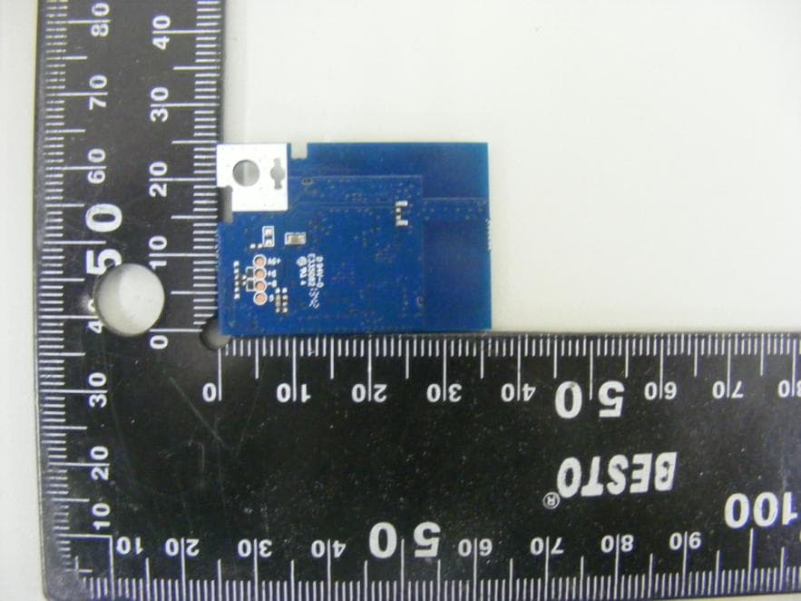
Click to zoom
Application Details
- Equipment Class
- DTS - Digital Transmission System
- Date of Grant
- Jan 05, 2014
- Application Purpose
- Original Equipment
- Date of Application
- Jan 05, 2014
- Equipment Note
- WDF210M WiFi module
- Frequency Range
- 2412.00000000 - 2462.00000000
- Company
- Samsung Electronics Co Ltd
- Country
- United States
Documents & Files
Document Text
Text extracted from the exhibit documents filed with the FCC. Open a document above to read the original.
Users Manual
Version 1.0 Samsung Electronics page 1 of 9 User Manual WDF210M 802.11b/g/n WLAN Module Version 1.0 Samsung Electronics page 2 of 9 Revision History 0.1 2013-10-18 Created 1. General Descriptions WDF210M is a Wi-Fi module compliant with IEEE802.11 b.g.n MAC/baseband/radio optimized for low- power applications. The core chipset is from Mediatek, part number MT7601U. The MT7601U is a highly integrated Wi-Fi single chip which supports 150 Mbps PHY rate. It fully complies with IEEE 802.11n and IEEE 802.11 b/g standards, offering feature-rich wireless connectivity at high standards, and delivering reliable, cost-effective throughput from an extended distance. Optimized RF architecture and baseband algorithms provide superb performance and low power consumption. Intelligent MAC design deploys a high efficient DMA engine and hardware data processing accelerators which offloads the host processor. The WDF210M is designed to support standard based features in the areas of security, quality of service and international regulations, giving end users the greatest performance any time and in any circumstance. 2. Features _ IEEE 802.11 b/g/n client _ Embedded high-performance 32-bit RISC microprocessor _ Highly integrated RF with 55nm CMOS technology _ 1T1R mode with support of 150Mbps PHY rate _ Integrate high efficiency switching regulator _ Best-in-class power consumption performance _ Compact 5mm x 5mm QFN40L package _ 1/2/3/4-wire PTA Wi-Fi / Bluetooth coexistence support _ 802.11 d/h/k compliant _ Security support for WFA WPA/WPA2 personal, WPS2.0, WAPI _ Supports 802.11w protected managed frames _ QoS support of WFA WMM, WMM PS _ Supports Wi-Fi Direct _ Fully compliance with USB v2.0 High-speed mode _ Per packet transmit power control _ Antenna diversity Version 1.0 Samsung Electronics page 3 of 9 3. Applications 4 Dimension and Pin Assignments 4.1 Mechanical Dimension Version 1.0 Samsung Electronics page 4 of 9 4.2 Pin Assignments Version 1.0 Samsung Electronics page 5 of 9 5. Absolute Maximum Ratings 6. DC Characteristics 7. Electrical Specification Version 1.0 Samsung Electronics page 6 of 9 8.RF Specification All measurements are made under nominal power supply and room temperature 25 °C unless specified. RF specification of SPW-B4319S was defined according to 802.11b/g mandatory 8.1 Supportable Modulation Scheme & Data Rates Version 1.0 Samsung Electronics page 7 of 9 8.2 RF Specification 8.2.1. Receiver 8.2.2. Transmitter Version 1.0 Samsung Electronics page 8 of 9 9. Notice This device complies with Part 15 of FCC Rules. Operation is Subject to following two conditions: (1) This device may not cause harmful interference, and (2) This device must accept any interference received including interference that cause undesired operation. This equipment has been tested and found to comply within the limits for a Class B digital device, pursuant to part 15 of the FCC Rules. These limits are designed to provide reasonable protection against harmful interference in a residential installation. This equipment generates, uses, and can radiate radio frequency energy and, if not installed and used in accordance with the instructions, may cause harmful interference to radio communications. However, there is no guarantee that interference will not occur in a particular installation. If this equipment does cause harmful interference to radio or television reception, which can be determined by turning the equipment off and on, the user is encouraged to try to correct the interference by one or more of the following measures: • Reorient or relocate the receiving antenna • Increase the separation between the equipment and receiver • Connect the equipment into an outlet on a different circuit from that to which the receiver is connected • Consult the dealer or an experienced radio/TV technician for help. The transmitter must not be co-located or operated in conjunction wit any other antenna or transmitter. The available scientific evidence does not show that any health problems are associated with using low power wireless devices. There is no proof, however, that these low power wireless devices are absolutely safe. Low power wireless devices emit low levels of radio frequency energy (RF) in the microwave range while being used. Whereas high levels of RF can produce health effects (by heating tissue), exposure to low-level RF that does not produce heating effects causes no known adverse health effects. Many studies of low-level RF exposures have not found any biological effects. Some studies have suggested that some biological effects might occur, but such findings have not been confirmed by additional research. To satisfy RF exposure requirements, this device and its antenna(s) must operate with a separation distance of at least 20 centimeters from all persons and must not be co-located or operated in conjunction with any other antenna or transmitter. End-users must be provided with specific operating instructions for satisfying RF exposure. FCC WARNING: Changes or modifications not expressly approved by the party responsible for compliance could void the user’s authority to operate the equipment. Version 1.0 Samsung Electronics page 9 of 9
Cover Letter(s)
129, Samsun g‐Ro, Yeongtong‐Gu, Suwon‐City Gyeonggi‐Do, 443‐742, Korea November 25, 2013 Federal Communications Commission Authorization and Evaluation Division 7435 Oakland Mills Road, Columbia, MD 21046 REQUEST OF CONFIDENTIALITY for FCC ID: A3LWDF210M To Whom It May Concern: Pursuant to Sections 0.457 and 0.459 of the Commission’s Rules (CFR 47), and Section 552 (b) (4) of the Freedom of Information Act, Samsung Electronics Co., Ltd. hereby requests confidentiality and treatment of certain information accompanying this application. The materials contain trade secrets and proprietary information not customarily released to the public. The public disclosure of these matters might be harmful to the Applicant and provide unjustified benefits to its competitors. We are also hereby request Short‐Term Confidentiality for 180 days after the grant as outlined in Public Notice DA 04‐1705. This provision will give Samsung Electronics Co., Ltd temporary confidentiality of commercially sensitive information prior to product release. The requested Permanent and Temporary Confidential exhibits are listed as follows: CONFIDENTIAL LIST Permanent 1 Block Diagram 2 Operational Descriptions 3 Schematics Short‐Term 4 External Photos 5 Internal Photos 6 Test Setup Photos 7 User’s Manual The Applicant understands that pursuant to Rule 0.457, disclosure of this application and all accompanying documentations, where applicable, will not be made public before the date of the Grant for this application. Sincerely Yours, Sang Kyung (Peter) Ra / General Manager SAMSUNG ELCTRONICS Co., Ltd.
Cover Letter(s)
129, Samsung‐Ro, Yeongtong‐Gu, Suwon‐City Gyeonggi‐Do, 443‐742, Korea November 25, 2013 Federal Communications Commission Authorization and Evaluation Division 7435 Oakland Mills Road, Columbia, MD 21046 LETTER OF AUTHORIZATION To whom it may concern: I, the undersigned, hereby authorize Lab Manager Feel. Jeong (or Logan. Lee) and of SGS Korea Co., Ltd. and hereafter referred to as SGS Korea, to act on our behalf in all manners relating to application for equipment authorization, including signing of all documents relating to these matters. Any and all acts carried out by Lab Manager Feel. Jeong (or Logan. Lee) of SGS Korea Co., Ltd. on our behalf shall have the same effect as acts of our own. I, the undersigned, hereby certify that we are not subject to a denial of federal benefits, that includes FCC benefits, pursuant to Section 5301 of the Anti‐Drug Abuse Act of 1988, 21 U.S.C. 853(a). In authorizing SGS Korea as our agent, we still recognize that we are responsible to: a) comply with the relevant provisions of the certification program; b) make all necessary arrangements for the conduct of the evaluation, including provision for examining documentation and access to all areas, records (including internal audit reports) and personnel for the purposes of evaluation (e.g. testing, inspection, assessment, surveillance, reassessment) and resolution of complaints; c) make claims regarding certification only in respect of the scope for which certification has been granted; d) do not use our product certification in such a manner as to bring the Certification Division into disrepute and not make any statement regarding our product certification which the Certification Division may consider misleading or unauthorized; e) upon suspension or cancellation of certification, discontinue use of all advertising matter that contains any reference thereto and return any certification documents as required by the Certification Division; f) use certification only to indicate the products are certified as being in conformity with specified standards; g) endeavor to ensure that no certificate or report nor any part thereof is used in a misleading manner; h) ensure that any reference to our product certification in communication media such as documents, brochures or advertising, complies with the requirements of the Certification Division; 129, Samsung‐Ro, Yeongtong‐Gu, Suwon‐City Gyeonggi‐Do, 443‐742, Korea i) keep a record of all complaints made known to the us relating to the product’s compliance with requirements of the relevant standard and to make these records available to the Certification Division when requested; j) take appropriate action with respect to such complaints and any deficiencies found in products or services that affect compliance with the requirements for certification; k) document the actions taken. This authorization is valid until further written notice from the applicant. Sincerely Yours Sang Kyung (Peter) Ra / General Manager SAMSUNG ELECTRONICS Co., Ltd.
Cover Letter(s)
Applicant/Grantee SAMSUNG ELECTRONICS Co., Ltd. FCC ID: A3LWDF210M Modular Transmitters Request for Modular Approval Request for Limited Modular Approval Requirements EUT Conditions Comply (Y/N) Single Modular Approval Requirements 1 The radio elements of the modular transmitter must have their own shielding. The physical crystal and tuning capacitors may be located external to the shielded radio elements. YES 2 The modular transmitter must have buffered modulation/data inputs (if such inputs are provided) to ensure that the module will comply with modular approval requirements under conditions of excessive data rates or over-modulation. YES 3 The modular transmitter must have its own power supply regulation. YES 4 The modular transmitter must comply with the antenna and transmission system requirements. YES 5 The modular transmitter must be tested in a stand-alone configuration, i.e., the module must not be inside another device during testing. Unless the transmitter module will be battery powered, it must comply with the AC line conducted requirements found in Section 15.207. AC or DC power lines and data input/output lines connected to the module must not contain ferrites, unless they will be marketed with the module (see Section 15.27(a)). The length of these lines shall be the length typical of actual use or, if that length is unknown, at least 10 centimeters to insure that there is no coupling between the case of the module and supporting equipment. Any accessories, peripherals, or support equipment connected to the module during testing shall be unmodified and commercially available (see Section 15.31(i)). YES 6 The modular transmitter must be equipped with either a permanently affixed label or must be capable of electronically displaying its FCC identification number. (A) If using a permanently affixed label, the modular transmitter must be labeled with its own FCC identification number, and, if the FCC identification number is not visible when the module is installed inside another device, then the outside of the device into which the module is installed must also display a label referring to the enclosed module. This exterior YES label can use wording such as the following: “Contains Transmitter Module FCC ID: XYZMODEL1” or “Contains FCC ID: XYZMODEL1.” Any similar wording that expresses the same meaning may be used. The Grantee may either provide such a label, an example of which must be included in the application for equipment authorization, or, must provide adequate instructions along with the module which explain this requirement. In the latter case, a copy of these instructions must be included in the application for equipment authorization. (B) If the modular transmitter uses an electronic display of the FCC identification number, the information must be readily accessible and visible on the modular transmitter or on the device in which it is installed. If the module is installed inside another device, then the outside of the device into which the module is installed must display a label referring to the enclosed module. This exterior label can use wording such as the following: “Contains FCC certified transmitter module(s).” Any similar wording that expresses the same meaning may be used. The user manual must include instructions on how to access the electronic display. A copy of these instructions must be included in the application for equipment authorization. 7 The modular transmitter must comply with any specific rules or operating requirements that ordinarily apply to a complete transmitter and the manufacturer must provide adequate instructions along with the module to explain any such requirements. A copy of these instructions must be included in the application for equipment authorization. YES 8 The modular transmitter must comply with any applicable RF exposure requirements in its final configuration. YES A limited modular approval may be granted for single or split modular transmitters that do not comply with all of the above requirements, e.g., shielding, minimum signaling amplitude, buffered modulation/data inputs, or power supply regulation, if the manufacturer can demonstrate by alternative means in the application for equipment authorization that the modular transmitter meets all the applicable Limited modular approval also may be granted in those instances where compliance with RF exposure rules is demonstrated only for particular product configurations. The applicant for certification must state how control of the end product into which the module will be installed will be maintained such that full compliance of the end product is always ensured.
External Photos
External photos of EUT Front view of EUT Rear view of EUT
ID Label/Location Info
FCC&IC Label 1. FCC/IC Label Drawing 2. FCC/IC Label Location MODEL: WDF210M FCC ID: A3LWDF210M IC: 649EWDF210M
Internal Photos
Model : WDF210M Internal photos of EUT Model : WDF210M Top view of Main PCB Bottom view of Main PCB Model : WDF210M View of Antenna Main Antenna Aux Antenna
RF Exposure Info
Report Number : F690501/RF-RTL007111-2 Page: 2 of 5 The results shown in this test report refer only to the sample(s) tested unless otherwise stated. This test report cannot be reproduced, except in full, without prior written permission of the Company. SGS Korea Co., Ltd. (Gunpo Laboratory) 18-34, Sanbon-dong, Gunpo-si, Gyeonggi-do, Korea, 435-040 Tel. +82 31 428 5700 / Fax. +82 31 427 2371 www.ee.sgs.com/korea INDEX Table of Contents Page 1. General Information -------------------------------------------------------------------------------- 3 2. RF Exposure Evaluation -------------------------------------------------------------------------- 4 Report Number : F690501/RF-RTL007111-2 Page: 3 of 5 The results shown in this test report refer only to the sample(s) tested unless otherwise stated. This test report cannot be reproduced, except in full, without prior written permission of the Company. SGS Korea Co., Ltd. (Gunpo Laboratory) 18-34, Sanbon-dong, Gunpo-si, Gyeonggi-do, Korea, 435-040 Tel. +82 31 428 5700 / Fax. +82 31 427 2371 www.ee.sgs.com/korea 1. General Information 1.1. Testing Laboratory SGS Korea Co., Ltd. (Gunpo Laboratory) - Wireless Div. 3FL, 18-34, Sanbon-dong, Gunpo-si, Gyeonggi-do, Korea 435-040 (Lab) - 413-15, Gomae-Dong, Giheung-Gu, Yongin-Si, Gyeonggi-Do, South Korea. (Chamber) All SGS services are rendered in accordance with the applicable SGS conditions of service available on request and accessible at http://www.sgs.com/en/Terms-and-Conditions.aspx. Telephone : +82 31 428 5700 FAX : +82 31 427 2371 1.2. Details of Applicant Applicant : SAMSUNG ELECTRONICS CO., LTD. Address : 129, Samsung-Ro, Yeongtong-Gu, Suwon-Si, Gyeonggi-Do, Korea Contact Person : Lee Jaywoo Phone No. : +82 31 436 7632 1.3. Description of EUT Kind of Product WDF210M WiFi module Model Name WDF210M Serial Number N/A Power Supply DC 5 V Frequency Range 2 412 ㎒ ~ 2 462 ㎒ (11b/g/n_HT20), 2 422 ㎒ ~ 2 452 ㎒ (11n_HT40) Modulation Technique DSSS, OFDM Number of Channels 11 channels (11b/g/n_HT20), 7 channels(11n_HT40) Antenna Type Internal type (MISO) Antenna Gain 2 412 ㎒ ~ 2 462 ㎒: 3.5 ㏈i 1.4. Test report revision Revision Report number Description 0 F690501/RF-RTL007111 Initial 1 F690501/RF-RTL007111-1 Added result of max power includes power tolerance 2 F690501/RF-RTL007111-2 Revised result of max power includes power tolerance Report Number : F690501/RF-RTL007111-2 Page: 4 of 5 The results shown in this test report refer only to the sample(s) tested unless otherwise stated. This test report cannot be reproduced, except in full, without prior written permission of the Company. SGS Korea Co., Ltd. (Gunpo Laboratory) 18-34, Sanbon-dong, Gunpo-si, Gyeonggi-do, Korea, 435-040 Tel. +82 31 428 5700 / Fax. +82 31 427 2371 www.ee.sgs.com/korea 2. RF Exposure Evaluation 2.1. Environmental evaluation and exposure limit according to FCC CFR 47 part 1, 1.1307(b), 1.1310 According to FCC 1.1310 : The criteria listed in the following table shall be used to evaluate the environment impact of human exposure to radio frequency (RF) radiation as specified in §1.1307(b) LIMITS FOR MAXIMUM PERMISSIBLE EXPOSURE (MPE) 2.1.1. Friis transmission formula: Pd = (Pout*G)/(4*pi*R 2 ) Where Pd = power density in ㎽/㎠ Pout = output power to antenna in ㎽ G = gain of antenna in linear scale Pi = 3.1416 R = distance between observation point and center of the radiator in ㎝ Pd the limit of MPE, 1 ㎽/㎠. If we know the maximum gain of the antenna and the total power input to the antenna, through the calculation, we will know the distance where the MPE limit is reached. 2.1.2. Test Result of RF Exposure Evaluation Test Item : RF Exposure Evaluation Data Test Mode : Normal Operation Frequency Range (㎒) Electric Field Strength(V/m) Magnetic Field Strength (A/m) Power Density (㎽/㎠) Average Time (A) Limits for Occupational /Control Exposures 300 – 1 500 -- -- F/300 6 1 500 – 100 000 -- -- 5 6 (B) Limits for General Population/Uncontrol Exposures 300 – 1 500 -- -- F/1500 6 1 500 – 100 000 -- -- 1 30 Report Number : F690501/RF-RTL007111-2 Page: 5 of 5 The results shown in this test report refer only to the sample(s) tested unless otherwise stated. This test report cannot be reproduced, except in full, without prior written permission of the Company. SGS Korea Co., Ltd. (Gunpo Laboratory) 18-34, Sanbon-dong, Gunpo-si, Gyeonggi-do, Korea, 435-040 Tel. +82 31 428 5700 / Fax. +82 31 427 2371 www.ee.sgs.com/korea 2.1.3. Output Power into Antenna & RF Exposure Evaluation Distance OFDM : 802.11g (The max. power includes the power tolerance) Channel Channel Frequency (㎒) Output Average Power to Antenna (㏈m) Antenna Gain (㏈i) Power Density at 20㎝ (㎽/㎠) Limits (㎽/㎠) Low 2 412 14.3 3.5 0.011 988 1 Note : 1. The power density Pd (5th column) at a distance of 20㎝ calculated from the friis transmission formula is far below the limit of 1 ㎽/㎠.
Test Report
Report Number: F690501/RF-RTL007110-2 Page: 2 of 75 The results shown in this test report refer only to the sample(s) tested unless otherwise stated. This test report cannot be reproduced, except in full, without prior written permission of the Company. SGS Korea Co., Ltd. (Gunpo Laboratory) 18-34, Sanbon-dong, Gunpo-si, Gyeonggi-do, Korea, 435-040 www.ee.sgs.com/korea RTT5041-20(2013.07.27)(1) Tel. +82 31 428 5700 / Fax. +82 31 427 2371 A4(210mmx297mm) INDEX Table of contents 1. General information -------------------------------------------------------------------------------------- 3 2. Transmitter radiated spurious emissions and conducted spurious emission -------------- 6 3. 6 ㏈ bandwidth & 99% Occupied Bandwidth----------------------------------------------------- 43 4. Maximum Conducted output power ----------------------------------------------------------------- 57 5. Power Spectral Density --------------------------------------------------------------------------------- 62 6. Transmitter AC Power Line Conducted Emission------------------------------------------------- 70 7. Antenna Requirement ----------------------------------------------------------------------------------- 75 Report Number: F690501/RF-RTL007110-2 Page: 3 of 75 The results shown in this test report refer only to the sample(s) tested unless otherwise stated. This test report cannot be reproduced, except in full, without prior written permission of the Company. SGS Korea Co., Ltd. (Gunpo Laboratory) 18-34, Sanbon-dong, Gunpo-si, Gyeonggi-do, Korea, 435-040 www.ee.sgs.com/korea RTT5041-20(2013.07.27)(1) Tel. +82 31 428 5700 / Fax. +82 31 427 2371 A4(210mmx297mm) 1. General Information 1.1. Testing Laboratory SGS Korea Co., Ltd. (Gunpo Laboratory) - Wireless Div. 3FL, 18-34, Sanbon-dong, Gunpo-si, Gyeonggi-do, Korea 435-040 All SGS services are rendered in accordance with the applicable SGS conditions of service available on request and accessible at http://www.sgs.com/en/Terms-and-Conditions.aspx. Telephone : +82 31 428 5700 FAX : +82 31 427 2371 1.2. Details of Applicant Applicant : SAMSUNG ELECTRONICS CO., LTD. Address : 129, Samsung-Ro, Yeongtong-Gu, Suwon-Si, Gyeonggi-Do, Korea Contact Person : Lee Jaywoo Phone No. : +82 31 277 2659 1.3. Details of Factory Information Applicant : SAMSUNG ELECTRONICS CO., LTD. Address : 129, Samsung-Ro, Yeongtong-Gu, Suwon-Si, Gyeonggi-Do, Korea 1.4. Description of EUT Kind of Product WDF210M WiFi module Model Name WDF210M Serial Number N/A Power Supply DC 5 V Frequency Range 2 412 ㎒ ~ 2 462 ㎒ (11b/g/n_HT20), 2 422 ㎒ ~ 2 452 ㎒ (11n_HT40) Modulation Technique DSSS, OFDM Number of Channels 11 channels (11b/g/n_HT20), 7 channels(11n_HT40) Antenna Type Internal type (MISO) Antenna Gain 2 412 ㎒ ~ 2 462 ㎒: 3.5 ㏈i Report Number: F690501/RF-RTL007110-2 Page: 4 of 75 The results shown in this test report refer only to the sample(s) tested unless otherwise stated. This test report cannot be reproduced, except in full, without prior written permission of the Company. SGS Korea Co., Ltd. (Gunpo Laboratory) 18-34, Sanbon-dong, Gunpo-si, Gyeonggi-do, Korea, 435-040 www.ee.sgs.com/korea RTT5041-20(2013.07.27)(1) Tel. +82 31 428 5700 / Fax. +82 31 427 2371 A4(210mmx297mm) 1.5. Test Equipment List Equipment Manufacturer Model S/N Cal Date Cal Interval Cal Due. Signal Generator R&S SMR40 100540 Jan. 08, 2013 Annual Jan. 08, 2014 Signal Generator R&S SMJ 100A 100882 Jul. 03, 2013 Annual Jul. 03, 2014 Spectrum Analyzer Agilent N9030A MY53120526 Jul. 30, 2013 Annual Jul. 30, 2014 Attenuator Mini circuits BW-N20W5+ 0950-4 Mar. 26, 2013 Annual Mar. 26, 2014 Attenuator AEROFLEX / WEINSCHEL 89-20-12 407 Jul. 03, 2013 Annual Jul, 03, 2014 Band Rejection Filter Wainwright WRCT2402/2480- 2400/2483.5-30/20SS 22 Jul. 02, 2013 Annual Jul. 02, 2014 High Pass Filter Wainwright WHK3.0/18G-6SS 4 Jul. 02, 2013 Annual Jul. 02, 2014 High Pass Filter Wainwright WHK7.5/26.5G-6SS 15 Jul. 03, 2013 Annual Jul. 03, 2014 Low Pass Filter Mini circuits NLP-1200+ V9500401023-1 Jul. 02, 2013 Annual Jul. 02, 2014 Power Sensor R&S NRP-Z81 101341 Jul. 04, 2013 Annual Jul. 04, 2014 DC Power Supply Agilent U8002A MY48490027 Jan. 08, 2013 Annual Jan. 08, 2014 Preamplifier R&S SCU-18 10070 Jun. 21, 2013 Annual Jun. 21, 2014 Preamplifier H.P. 8447D 2727A05143 Aug. 08, 2013 Annual Aug. 08, 2014 Preamplifier MITEQ Inc. JS44-18004000-35-8P 1546891 Jun. 13, 2013 Annual Jun. 13, 2014 Test Receiver R & S ESU40 100075 Feb. 15 2013 Annual Feb. 15 2014 Bilog Antenna SCHWARZBEC K VULB9163 9163-437 Oct. 04, 2012 Biennial Oct. 04, 2014 Horn Antenna R&S HF906 100608 Aug. 13, 2012 Biennial Aug. 13, 2014 Horn Antenna SCHWARZBECK BBHA9170 BBHA9170431 May 15, 2012 Biennial May 15, 2014 Turn Table DT-3000S-3T INN-CO N/A N.C.R. N.C.R. N.C.R. Test Receiver R&S ESU8 100128 Jan. 25, 2013 Annual Jan. 25, 2014 Antenna Master MA4000-EP INN-CO N/A N.C.R. N.C.R. N.C.R. Anechoic Chamber SY Corporation L × W × H (21.5 m × 13.0 m × 9.0 m) N/A N.C.R. N.C.R. N.C.R. EMI Test Receiver R & S ESU8 100128 Jan. 25, 2013 Annual Jan. 25, 2014 Two-Line V-Network R & S ENV216 101180 May 15, 2013 Annual May 15, 2014 ▶ Support equipment Description Manufacturer Model Serial Number N/A - - - Report Number: F690501/RF-RTL007110-2 Page: 5 of 75 The results shown in this test report refer only to the sample(s) tested unless otherwise stated. This test report cannot be reproduced, except in full, without prior written permission of the Company. SGS Korea Co., Ltd. (Gunpo Laboratory) 18-34, Sanbon-dong, Gunpo-si, Gyeonggi-do, Korea, 435-040 www.ee.sgs.com/korea RTT5041-20(2013.07.27)(1) Tel. +82 31 428 5700 / Fax. +82 31 427 2371 A4(210mmx297mm) 1.6. Summary of Test Results The EUT has been tested according to the following specifications: APPLIED STANDARD: FCC Part15 Subpart C § 15.247, RSS-210 Issue8, RSS-Gen Issue3 Standard section Test Item(s) Result 15.205 15.209 15.247(d) RSS-210 A8.5 Transmitter Radiated Spurious Emissions Conducted Spurious Emission Complied 15.247(a)(2) R…
Text truncated - open the document above for the full version.
Test Setup Photos
Test setup photo of EUT A. Photo of Radiated Spurious Emission Test (Below 1GHz) B. Photo of Radiated Spurious Emission Test (Above 1GHz) C. Photo of Transmitter AC Power Line Conducted Emission Test
Contact Information
Applicant
Jenni Chun(General Manager)
Test Firm
SGS Korea Co., Ltd.Forest Lee
Technical Specifications
| # | Rule Parts | Frequency Range | Power Output |
|---|---|---|---|
| 1 | 15C | 2.41 GHz - 2.46 GHz | 207.00 mW |
Other Applications from Samsung Electronics Co Ltd
A3LSMS741B
Aug 05, 2026Portable Handset
Equipment Class
6VL - 15E 6 GHZ Very Low Power DeviceA3LSMX940
Jul 31, 2026BT,BLE Tablet DTS,UNII a,b,g,n,ac,ax,be and digitizer
Equipment Class
DTS - Digital Transmission SystemA3LSMS741U
Jul 30, 2026Portable Handset
Equipment Class
6CD - 15E 6 GHz Low Power Dual ClientA3LSMX840
Jul 27, 2026BT,BLE Tablet DTS,UNII a,b,g,n,ac,ax and Digitizer
Equipment Class
DSS - Part 15 Spread Spectrum TransmitterA3LSMX848U
Jul 27, 2026WCDMA, LTE, 5G NR Tablet BT,BLE, DTS,UNII a b g n ac ax and Digitizer
Equipment Class
JBP - Part 15 Class B Computing Device Peripheral