A3LYPG1Mobile Internet Device
Samsung Electronics Co Ltd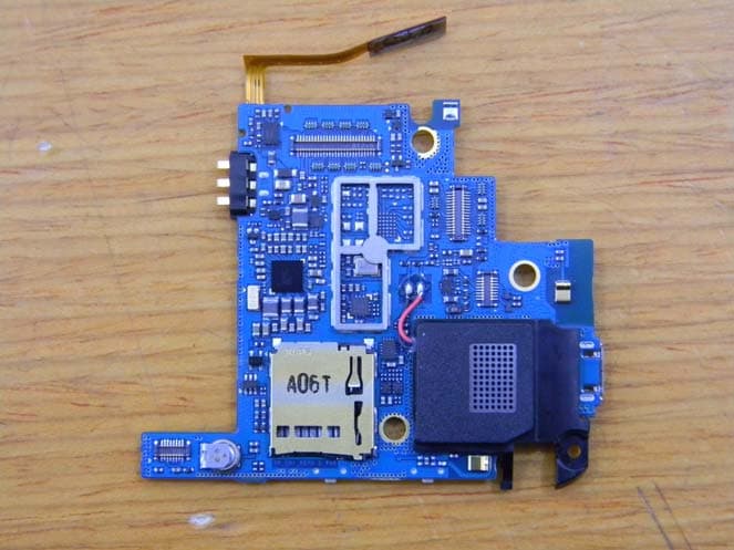
Click to zoom
Application Details
- Equipment Class
- DTS - Digital Transmission System
- Date of Grant
- Mar 28, 2011
- Application Purpose
- Original Equipment
- Date of Application
- Mar 28, 2011
- Equipment Note
- Mobile Internet Device
- Frequency Range
- 2412.00000000 - 2462.00000000
- Company
- Samsung Electronics Co Ltd
- Country
- United States
Documents & Files
Document Text
Text extracted from the exhibit documents filed with the FCC. Open a document above to read the original.
Users Manual
Some of the contents in this manual may differ from your device depending on the software of the device or your service provider. www.samsungmobile.comEnglish (EU). 02/2011. Rev. 1.0 To install Kies (PC Sync) Download the latest version of Kies from the Samsung 1. website (www.samsung.com/kies) and install it on your PC. Using a PC data cable, connect your device to your PC.2. Refer to the Kies help for more information. YP-G1 user manual Using this manual 2 Using this manual Thank you for purchasing this Samsung YP-G1. This device will provide you with entertainment based on Samsung’s exceptional technology and high standards. This user manual has been specially designed to guide you through the functions and features of your device. Read me first Please read all safety precautions and this manual • carefully before using your device to ensure safe and proper use. The descriptions in this manual are based on the default • settings of your device. Images and screenshots used in this user manual may • differ in appearance from the actual product. Content in this user manual may differ from the product, • or from software provided by service providers or carriers, and is subject to change without prior notice. Refer to www.samsungmobile.com for the latest version of the user manual. Available features and additional services may vary by • device, software, or service provider. Formatting and delivery of this user manual is based • on Google Android operating systems and may vary depending on the user’s operating system. Applications and their functions may vary by country, • region, or hardware specifications. Samsung is not liable for performance issues caused by third-party applications. Samsung is not liable for performance issues or • incompatibilities caused by user editing of registry settings. You may upgrade your mobile device’s software by • accessing www.samsungmobile.com. Using this manual 3 Note—notes, usage tips, or additional information ► Refer to—pages with related information; for example: ► p.12 (represents “see page 12”) → Followed by—the order of options or menus you must select to perform a step; for example: In Idle mode, open the application list and select Settings → About phone (represents Settings, followed by About phone) [] Square brackets—device keys; for example: [ ] (represents the Power/Lock key) Sound sources, wallpapers, and images provided in this • device are licenced for limited use between Samsung and their respective owners. Extracting and using these materials for commercial or other purposes is an infringement of copyright laws. Samsung is not liable for such copyright infringement by the user. Please keep this manual for future reference. • Instructional icons Before you start, familiarise yourself with the icons you will see in this manual: Warning—situations that could cause injury to yourself or others Caution—situations that could cause damage to your device or other equipment Using this manual 4 Trademarks SAMSUNG and the SAMSUNG logo are registered • trademarks of Samsung Electronics. The Android logo, Google Search • ™ , Google Maps ™ , Google Mail ™ , YouTube ™ , Android Market ™ , and Google Talk ™ are trademarks of Google, Inc. Bluetooth • ® is a registered trademark of the Bluetooth SIG, Inc. worldwide. Oracle and Java are registered trademarks of Oracle and/ • or its affiliates. Other names may be trademarks of their respective owners. Windows Media Player • ® is a registered trademark of Microsoft Corporation. Wi-Fi • ® , the Wi-Fi CERTIFIED logo, and the Wi-Fi logo are registered trademarks of the Wi-Fi Alliance. Copyright Copyright © 2011 Samsung Electronics This user manual is protected under international copyright laws. No part of this user manual may be reproduced, distributed, translated, or transmitted in any form or by any means, electronic or mechanical, including photocopying, recording, or storing in any information storage and retrieval system, without the prior written permission of Samsung Electronics. Using this manual 5 ABOUT DIVX VIDEO DivX ® is a digital video format created by DivX, Inc. This is an official DivX Certified ® device that plays DivX video. Visit www.divx.com for more information and software tools to convert your files into DivX video. DivX Certified ® to play DivX ® video up to HD 720p, including premium content. ABOUT DIVX VIDEO-ON-DEMAND This DivX Certified ® device must be registered in order to play purchased DivX Video-on-Demand (VOD) movies. To obtain your registration code, locate the DivX VOD section in your device setup menu. Go to vod.divx.com for more information on how to complete your registration. DivX • ® , DivX Certified ® , and associated logos are trademarks of DivX, Inc. and are used under licence. All other trademarks and copyrights are the property of • their respective owners. Contents 6 Contents Assembling ........................................... 10 Unpack ................................................................ 10 Install the battery ............................................. 11 Charge the battery ........................................... 12 Insert a memory card (optional) ................... 14 Attach a hand strap (optional) ...................... 16 Getting started ..................................... 17 Turn your device on and off ........................... 17 Get to know your device ................................. 17 Use the touch screen ........................................ 20 Lock or unlock the touch screen and keys . . 21 Get to know the idle screen ........................... 21 Access applications .......................................... 24 Customise your device .................................... 26 Enter text ............................................................ 28 Download applications from Android Market ................................................................. 31 Download files from the web ........................ 32 Synch…
Text truncated - open the document above for the full version.
ID Label/Location Info
FCC/IC Label 1. FCC/IC Label Location : It will be printed on the bottom side of EUT. Bottom side of EUT
Internal Photos
Internal photos of EUT view of EUT Top view of Main PCB Bottom view of Main PCB Top view of LCD PCB Bottom view of LCD PCB Top view of Sensor PCB Bottom view of Sensor PCB Top view of BT & WLAN Antenna BT & WLAN Antenna
RF Exposure Info
FCC ID: A3LYPG1 Report Number: FI-068-S1 Page : 1 of 29 SAMSUNG Electronics C0. LTD EUT Type: Mobile Internet Device Issue Date : Mar.03, 2011 SAMSUNG ELECTRONICS Co., Ltd., Regulatory Compliance Group IT R&D Center 416, Maetan-3dong, Yeongtong-gu, Suwon-si, Gyeonggi-do, Korea 443-742 TEST REPORT ON SAR Model Tested: YP-G1 FCC ID (Requested): A3LYPG1 IC ID (Requested): 649E-YPG1 Job No: FI-068 Report No: FI-068-S1 - Abstract – This document reports on SAR Tests carried out in accordance with FCC/OET Bulletin 65, Supplement C(July 2001). Prepared By MK YOUN - Test Engineer Authorized By JD JANG - Technical Manager FCC ID: A3LYPG1 Report Number: FI-068-S1 Page : 2 of 29 SAMSUNG Electronics C0. LTD EUT Type: Mobile Internet Device Issue Date : Mar.03, 2011 Contents 1. GENERAL INFORMATION .............................................................................. 3 2. DESCRIPTION OF DEVICE ............................................................................ 3 3. DESCRIPTION OF TEST EQUIPMENT .......................................................... 4 3.1 SAR Measurement Setup ............................................................................................................... 4 3.2 E-field Probe ................................................................................................................................... 5 3.3 Phantom.......................................................................................................................................... 7 3.4 Brain Simulating Mixture Characterization .................................................................................... 9 3.5 Device Holder for Transmitters........................................................................................................ 9 3.6 Validation Dipole ........................................................................................................................... 10 3.7 Equipment Calibration................................................................................................................... 11 4. SAR MEASUREMENT PROCEDURE ........................................................... 12 5. DESCRIPTION OF TEST POSITION ............................................................ 13 5.1 SAM Phantom Shape.................................................................................................................... 13 5.2 “cheek” Position ............................................................................................................................ 13 5.3 “tilted” Position .............................................................................................................................. 15 5.4 Body Holster/Belt Clip Configurations ........................................................................................... 16 6. MEASUREMENT UNCERTAINTY ................................................................. 18 7. SYSTEM VERIFICATION............................................................................... 19 7.1 Tissue Verification ......................................................................................................................... 19 7.2 Test System Validation .................................................................................................................. 19 8. SAR MEASUREMENT RESULTS.................................................................. 20 8.1 WLAN Head SAR Results ............................................................................................................. 25 8.2 WLAN Body SAR Results(Without Holster) .................................................................................. 26 9. CONCLUSION ............................................................................................... 27 10. REFERENCES ............................................................................................. 28 APPENDIX A SAR Definition ........................................................................... 30 APPENDIX B Probe Calibration Process ........................................................ 31 APPENDIX C ANSI/IEEE C95.1 – 2005 RF EXPOSURE LIMITS.................. 32 APPENDIX D The Validation Measurements .................................................. 33 APPENDIX E Plots of The SAR Measurements.............................................. 35 APPENDIX F Probe Calibration ...................................................................... 48 APPENDIX G Calibration of The Validation Dipole ......................................... 60 FCC ID: A3LYPG1 Report Number: FI-068-S1 Page : 3 of 29 SAMSUNG Electronics C0. LTD EUT Type: Mobile Internet Device Issue Date : Mar.03, 2011 1. GENERAL INFORMATION Test Dates : Feb.28, 2011 Manufacturer : SAMSUNG ELECTRONICS Co., Ltd. Address : 416 Maetan3-Dong, Suwon City, Korea Test Standard : §2.1093; FCC/OET Bulletin 65, Supplement C(July 2001) FCC Classification : Digital Transmission System (DTS) Tested for : FCC/TCB Certification 2. DESCRIPTION OF DEVICE Test Sample : Mobile Internet Device Model Number : YP-G1 Serial Number : Identical prototype (S/N : # FI-068-A) Tx Freq. Range : 2412 ~ 2462 MHz (WLAN) Rx Freq. Range : 2412 ~ 2462 MHz (WLAN) Antenna Manufacturer : Partron Model No.: YP-MB2(BT) Antenna Dimensions : 24.55 * 3.87 * 0.50 mm (W X L X T) FCC ID: A3LYPG1 Report Number: FI-068-S1 Page : 4 of 29 SAMSUNG Electronics C0. LTD EUT Type: Mobile Internet Device Issue Date : Mar.03, 2011 3. DESCRIPTION OF TEST EQUIPMENT 3.1 SAR Measurement Setup Robotic System Measurements are performed using the DASY4 (or DASY5) automated dosimetric assessment system. Which is made by Schmid & Partner Engineering AG (SPEAG) in Zurich, Switzerland and consists of high precision robotics system (Stäubli), robot controller, measurement server, Samsung computer, near-field probe, probe alignment sensor, and the SAM twin phantom containing the brain equivalent material. The robot is a six-axis …
Text truncated - open the document above for the full version.
Test Report
Report Number: F690501/RF-RTL004523 Page: 2 of 57 The results shown in this test report refer only to the sample(s) tested unless otherwise stated. This test report cannot be reproduced, except in full, without prior written permission of the Company. SGS Testing Korea Co., Ltd. 8-34, Sanbon-dong, Gunpo-si, Gyeonggi-do, Korea, 435-040 Tel. +82 31 428 5700 / Fax. +82 31 427 2371 www.electrolab.kr.sgs.com INDEX Table of contents 1. General information -------------------------------------------------------------------------------------- 3 2. Transmitter radiated spurious emissions and conducted spurious emission -------------- 6 3. Receiver Radiated Spurious Emission -------------------------------------------------------------- 25 4. 6 ㏈ bandwid th ------------------------------------------------------------------------------------------- 27 5. Maximum peak output power -------------------------------------------------------------------------- 39 6. Power Spectral Density --------------------------------------------------------------------------------- 41 7. Transmitter AC Power Line Conducted Emission------------------------------------------------- 48 8. Receiver AC Power Line Conducted Emission --------------------------------------------------- 53 9. Antenna Requirement ----------------------------------------------------------------------------------- 57 Report Number: F690501/RF-RTL004523 Page: 3 of 57 The results shown in this test report refer only to the sample(s) tested unless otherwise stated. This test report cannot be reproduced, except in full, without prior written permission of the Company. SGS Testing Korea Co., Ltd. 8-34, Sanbon-dong, Gunpo-si, Gyeonggi-do, Korea, 435-040 Tel. +82 31 428 5700 / Fax. +82 31 427 2371 www.electrolab.kr.sgs.com 1. General Information 1.1. Testing Laboratory SGS Testing Korea Co., Ltd. - Wireless Div. 2FL, 18-34, Sanbon-dong, Gunpo-si, Gyeonggi-dong, Korea - 705, Dongcheon-dong Suji-gu, Yongin-si, Gyeonggi-do, Korea www.electrolab.kr.sgs.com Telephone : +82 +31 428 5700 FAX : +82 +31 427 2371 1.2. Details of Applicant Applicant : Samsung Electronics Co., Ltd. Address : 416, Maetan3-dong, Yeongtong-gu, Suwon-si, Gyeonggi-do, Korea Contact Person : Bang, Jeong-Yeol Phone No. : +82 +31 301 4542 1.3. Details of Factories Information Name : Samsung Electronic Technical 2-Factory Address : 94-1, Imsu-dong, Gumi-si, Gyeongsangbuk-do, Korea, Republic of Name : Samsung Electronic Indonesia Co. Ltd. Address : Cikarang Industrial Estate JI, Jababeka Raya Blok F 29-33 Cikarang, Bekasi 17530, Indonesia Name : Samsung Electronic Huizhou Co. Ltd. Address : Industrial Complex Chenjiang Town, Huizhou City, Guangdong Province, China 1.4. Description of EUT Kind of Product Mobile Internet Device Model Name YP-G1(Additional model name: YP-G1**, YP-G1***) Serial Number N / A Power Supply DC 3.7 V (Li-ion Battery) Frequency Range 2 412 ~ 2 462 ㎒ (802.11b/g/n-HT20_SISO) Modulation Technique DSSS, OFDM Number of Channels 11 Antenna Type Integral Type Antenna Gain -1.55 ㏈i 1.5. Declaration by the manufacturer - WLAN & BT con not transmit simultaneously. - 802.11n supports HT20 mode only. Report Number: F690501/RF-RTL004523 Page: 4 of 57 The results shown in this test report refer only to the sample(s) tested unless otherwise stated. This test report cannot be reproduced, except in full, without prior written permission of the Company. SGS Testing Korea Co., Ltd. 8-34, Sanbon-dong, Gunpo-si, Gyeonggi-do, Korea, 435-040 Tel. +82 31 428 5700 / Fax. +82 31 427 2371 www.electrolab.kr.sgs.com 1.6. Test Equipment List EQUIPMENT MANUFACTURER MODEL CAL DUE. Signal Generator R & S SMR40 Jul. 18, 2011 Spectrum Analyzer R & S FSV30 May 31, 2011 Spectrum Analyzer R & S FSP40 Jul. 15, 2011 Preamplifier H.P 8447F Jul. 05, 2011 Preamplifier Agilent 8449B Apr. 01, 2011 High Pass Filter Wainwright WHK3.0/18G-10SS Sep. 29, 2011 Power Sensor R & S NRP-Z81 Aug. 14. 2011 Test Receiver R & S ESU26 Apr. 08, 2011 Bilog Antenna SCHWARZBECK MESSELEKTRONIK VULB9163 Jul. 22, 2011 Horn Antenna R & S HF 906 Oct. 08, 2011 Horn Antenna SCHWARZBECK MESSELEKTRONIK BBHA9170 Mar. 17 2012 Anechoic Chamber SY Corporation L × W × H (9.6 m×6.4 m×6.6 m) N.C.R. Two-Line V-Network R & S ENV216 Jan. 04, 2012 Test Receiver R & S ESHS10 Jul. 13, 2011 Anechoic Chamber SY Corporation L × W × H (6.5 m×3.5 m×3.5 m) N.C.R 1.7. Details of added models Model Information YP-G1 Basic model YP-G1**, YP-G1*** The mark “*” means the memory capacity and color of product excluding product at Canada. Report Number: F690501/RF-RTL004523 Page: 5 of 57 The results shown in this test report refer only to the sample(s) tested unless otherwise stated. This test report cannot be reproduced, except in full, without prior written permission of the Company. SGS Testing Korea Co., Ltd. 8-34, Sanbon-dong, Gunpo-si, Gyeonggi-do, Korea, 435-040 Tel. +82 31 428 5700 / Fax. +82 31 427 2371 www.electrolab.kr.sgs.com 1.8. Summary of Test Results The EUT has been tested according to the following specifications: APPLIED STANDARD:FCC Part15 subpart B&C, RSS-210, RSS-Gen Standard section Test Item Result 15.205(a) 15.209 15.247(d) A8.5 Transmitter Radiated Spurious Emissions Conducted Spurious Emission Complied 15.109(a) RSS-Gen 6 Receiver Radiated Spurious Emission Complied 15.247(a)(2) A8.2(a) 6 dB Bandwidth and 99% BW Complied 15.247(b)(3) A8.4(4) Maximum Peak Output Power Complied 15.247(e) A8.3(2) Power Spectral Density Complied 15.207 RSS-Gen 7.2.4 Transmitter AC Power Line Conducted Emission Complied 15.107 RSS-Gen 7.2.4 Receiver AC Power Line Conducted Emission Complied 1.9. Conclusion of worst-case The field strength of spurious emission was measured in three orthogonal EUT positions(X-axis, Y-axis and Z-axis). Worst case is Y-axis. 1 Mbps is the highest ou tput power in the 11b. 6 Mbps is the highest output power in the 1 1g. In case of 11n, we chose MCS0 mode. 1.10. Test report revision Revision Report number Description 0 F690501/RF-RTL…
Text truncated - open the document above for the full version.
Test Setup Photos
FCC SAR Test Setup Photographs 1.5cm
Test Setup Photos
Test setup photos of EUT A. Photo of Spurious Emission Test B. Photos of conducted power line test for WLAN C. Photos of conducted power line test for Bluetooth
Contact Information
Applicant
Jenni Chun(General Manager)
Test Firm
SGS Korea Co., Ltd.Forest Lee
Technical Specifications
| # | Rule Parts | Frequency Range | Power Output |
|---|---|---|---|
| 2 | 15C | 2.41 GHz - 2.46 GHz | 277.00 mW |
Other Applications from Samsung Electronics Co Ltd
A3LSMS741B
Aug 05, 2026Portable Handset
Equipment Class
6VL - 15E 6 GHZ Very Low Power DeviceA3LSMX940
Jul 31, 2026BT,BLE Tablet DTS,UNII a,b,g,n,ac,ax,be and digitizer
Equipment Class
DTS - Digital Transmission SystemA3LSMS741U
Jul 30, 2026Portable Handset
Equipment Class
6CD - 15E 6 GHz Low Power Dual ClientA3LSMX840
Jul 27, 2026BT,BLE Tablet DTS,UNII a,b,g,n,ac,ax and Digitizer
Equipment Class
DSS - Part 15 Spread Spectrum TransmitterA3LSMX848U
Jul 27, 2026WCDMA, LTE, 5G NR Tablet BT,BLE, DTS,UNII a b g n ac ax and Digitizer
Equipment Class
JBP - Part 15 Class B Computing Device Peripheral