A4KTS211TPMS Sensor
DIAS Automotive Electronic Systems Co., Ltd.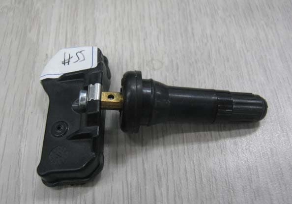
Click to zoom
Application Details
- Equipment Class
- DSC - Part 15 Security/Remote Control Transmitter
- Date of Grant
- Dec 14, 2011
- Application Purpose
- Original Equipment
- Date of Application
- Dec 14, 2011
- Equipment Note
- TPMS Sensor
- Frequency Range
- 433.92000000 - 433.92000000
- Country
- China
Documents & Files
Document Text
Text extracted from the exhibit documents filed with the FCC. Open a document above to read the original.
Users Manual
1 TPMS USER MANUAL 2 CONTENTS 1. INTRODUCTION OF TPMS ............................................................... 4 2. BILL OF TPMS ASSEMBLY ............................................................... 4 3. TPMS PRODUCT SPECIFICATION .................................................. 5 4. DISPLAY INTERFACE INTRODUCTION ........................................... 7 5. FUNCTION INTRODUCTION ............................................................ 8 5.1 NORMAL DISPLAY OF TEMPERATURE AND PRESSURE.............. 8 5.2 LOW PRESSURE ALARM ................................................................. 9 5.3 HIGH PRESSURE ALARM ................................................................ 9 5.4 FAST-LEAKING SETTING ............................................................... 10 5.5 HIGH TEMPERATURE ALARM ....................................................... 11 5.6 SENSOR MALFUNCTION ALARM .................................................. 11 6. TYRE INTERCHANGE SETTING INTRODUCTION........................ 13 6.1 STANDARD TYRE PRESSURE SETTING ...................................... 13 6.2 TYRE INTERCHANGE SETTING ....................................................13 7. TECHNOLOGY PARAMETERS .......................................................15 7.1 TPMS DISPLAY............................................................................... 15 7.2 TPMS SENSOR ............................................................................... 15 8. ANNEX............................................................................................. 16 3 Federal Communication Commission Interference Statement This equipment has been tested and found to comply with the limits for a Class B digital device, pursuant to Part 15 of the FCC Rules. These limits are designed to provide reasonable protection against harmful interference in a residential installation. This equipment generates uses and can radiate radio frequency energy and, if not installed and used in accordance with the instructions, may cause harmful interference to radio communications. However, there is no guarantee that interference will not occur in a particular installation. If this equipment does cause harmful interference to radio or television reception, which can be determined by turning the equipment off and on, the user is encouraged to try to correct the interference by one of the following measures: - Reorient or relocate the receiving antenna. - Increase the separation between the equipment and receiver. - Connect the equipment into an outlet on a circuit different from that to which the receiver is connected. - Consult the dealer or an experienced radio/TV technician for help. This device complies with Part 15 of the FCC Rules. Operation is subject to the following two conditions: (1) This device may not cause harmful interference, and (2) this device must accept any interference received, including interference that may cause undesired operation. FCC Caution: Any changes or modifications not expressly approved by the party responsible for compliance could void the user's authority to operate this equipment. 4 1. INTRODUCTION OF TPMS TPMS is the shortened form of tyre pressure monitoring system. TPMS is the active safety system of vehicle. It is used for real-time monitoring tyre pressure and tyre temperature and transmitting the information of tyre to driver timely and accurately. TPMS can reduce the risk of tyre blowing and damaging resulted from low pressure, high pressure, and high temperature and leaking. Thus protect effectively the life and property of drivers and passengers. TPMS display can be installed directly in air-conditioning vent in cab. It can be also installed in other suitable position through mushroom stick. The four sensors are installed inside tyre respectively. When the vehicle starts and its speed is higher than 20km/h, the sensors installed inside tyre can real time collect the tyre pressure, tyre temperature and so on. Then the information is transmitted by radio to TPMS display. TPMS display displays corresponding information after it receives the wireless signal and alarms when the tyre is abnormal. 2. BILL OF TPMS ASSEMBLY Serial number name AmountUnit 1 Tyre pressure sensor 4 PCS 2 Tyre pressure monitoring display 1 PCS 3 Power supply wiring harness 1 PCS 4 Clip 1 PCS 5 Mushroom stick 1 PCS 5 3. TPMS PRODUCT SPECIFICATION SET T/P NEXT Indication Light Power Supply Interface Fig 1 TPMS Display Fig 2 TPMS Sensor Indicator light introduction ① Green:State indication that shows the system is normal and has no alarm information; ② Red:Alarm indication that shows alarm information exists in the system. 6 Key introduction: ① “SET” is the key used for setting. The tyre interchange can be done with this key. The particular operation is as the following paragraph 6: Tyre Interchange Setting Specification. ② “T/P” is the key used for switching the display value of temperature and pressure. Through pressing this key, the value of tyre temperature and tyre pressure on the display can be switched. The tyre ID can be shown on the display after that “T/P” is pressed for 4s. Then press “NEXT”, we can inquire the ID of different tyre. The display of tyre ID can exit through pressing “SET”. ③ “NEXT” is the key that after you press the key for 4s, TPMS comes into matching mode. In this mode, the sensors can be changed by users. Press “NEXT” again, the matching mode can exit. Warm Reminders: When install the TPMS display, don’t install it above air-bag without fail for fear of additional injury to drivers and passengers when the air-bag opens under emergency conditions. If you need to change the sensors, please go to designated 4S shop or vehicle repair garage to do the matching using special tool by career man. If your hub is steel and you need to change the tyre, please change tyre together with valve of tyre pressure sensor. All the figures in the introduction are only the sketch map. Please refer…
Text truncated - open the document above for the full version.
Cover Letter(s)
DIAS Automotive Electronic Systems Co., Ltd. Agent Authorization Letter 2011-12-6 To: Federal Communications Commission 7435 Oakland Mills Road Columbia, MD 21046-1609 Curtis-Straus LLC TCB One Distribution Center Circle #1 Littleton, MA 01460 We, the undersigned DIAS Automotive Electronic Systems Co., Ltd. hereby authorize BUREAU VERITAS ADT Shanghai to act on our behalf in all matt ers relating to all processes required for FCC certification of our devices. Any and all acts carried out by the above agent on our behalf shall have the same effects as acts of our own. This authorization is valid until: 2012-12-6 If you have any questions regarding this authorization, let us know please. Sincerely, Name Gu Changfei Title R&D supervisor Signature
Internal Photos
Antenna Antenna Antenna
Test Report
FCC ID: A4KTS211 Report No.: DSA-11OC0107MBCY-FCC 1 FCC TEST REPORT REPORT NO.:DSA-11OC0107MBCY-FCC MODEL NO.:D500050000 RECEIVED:Oct. 18, 2011 ISSUED:Nov. 25, 2011 APPLICANT: DIAS AUTOMOTIVE ELECTRONIC SYSTEMS CO., LTD ADDRESS: 6th Floor, 3 Building, No. 615, Ning Qiao, Pudong, Shanghai ISSUED BY: BUREAU VERITAS ADT (Shanghai) Corporation LAB LOCATION: 2F, Building C, No.1618, Yishan rd., 201103, Shanghai, China This test report consists of 27 pages in total. It may be duplicated completely for legal use with the approval of the applicant. It should not be reproduced except in full, without the written approval of our laboratory. The client should not use it to claim product certification, approval, or endorsement by A2LA, CNAS, or any government agency. The test results in the report only apply to the tested item. The test results in this report are traceable to the national or international standards. V 1.0.0 FCC ID: A4KTS211 Report No.: DSA-11OC0107MBCY-FCC 2 Table of Contents 1 CERTIFICATION .......................................................................................... 3 2 SUMMARY OF TEST RESULTS .................................................................. 4 2.1 MEASUREMENT UNCERTAINTY............................................................... 4 3 GENERAL INFORMATION........................................................................... 5 3.1 GENERAL DESCRIPTION OF EUT ............................................................ 5 3.2 DESCRIPTION OF TEST MODES .............................................................. 5 3.3 GENERAL DESCRIPTION OF APPLIED STANDARDS.............................. 7 3.4 DESCRIPTION OF SUPPORT UNITS ........................................................ 7 4 EMISSION TEST.......................................................................................... 8 4.1 CONDUCTED EMISSION MEASUREMENT............................................... 8 4.1.1 LIMITS OF CONDUCTED EMISSION MEASUREMENT ............................ 8 4.1.2 TEST RESULTS .......................................................................................... 8 4.2 DEACTIVATION TIME ................................................................................. 9 4.2.1 LIMITS OF DEACTIVATION TIME MEASUREMENT .................................. 9 4.2.2 TEST INSTRUMENTS................................................................................. 9 4.2.3 TEST PROCEDURES ................................................................................. 9 4.2.4 DEVIATION FROM TEST STANDARD........................................................ 9 4.2.5 TEST SETUP............................................................................................... 9 4.2.6 TEST RESULTS ........................................................................................ 10 4.3 RADIATED EMISSION MEASUREMENT.................................................. 12 4.3.1 LIMITS OF RADIATED EMISSION MEASUREMENT............................... 12 4.3.2 TEST INSTRUMENTS............................................................................... 14 4.3.3 TEST PROCEDURE.................................................................................. 15 4.3.4 DEVIATION FROM TEST STANDARD...................................................... 15 4.3.5 TEST SETUP............................................................................................. 16 4.3.6 EUT OPERATING CONDITIONS .............................................................. 16 4.3.7 TEST RESULTS ........................................................................................ 17 4.4 20DB OCCUPIED BANDWIDTH MEASUREMENT .................................. 24 4.4.1 LIMITS OF BAND EDGES MEASUREMENT ............................................ 24 4.4.2 TEST INSTRUMENTS............................................................................... 24 4.4.3 TEST PROCEDURES ............................................................................... 25 4.4.4 DEVIATION FROM TEST STANDARD...................................................... 25 4.4.5 TEST SETUP............................................................................................. 25 4.4.6 TEST RESULTS ........................................................................................ 26 5 APPENDIX - INFORMATION ON THE TESTING LABORATORIES .......... 27 FCC ID: A4KTS211 Report No.: DSA-11OC0107MBCY-FCC 3 1 CERTIFICATION PRODUCT: TPMS sensor MODEL NO.: N/A APPLICANT: D500050000 TESTED: Oct. 26 ~Nov. 20, 2011 TEST ITEM: Engineering Sample STANDARDS: FCC Part 15:2010, Subpart C (Section 15.209 and 15.231), ANSI C63.4-2003 We, BUREAU VERITAS ADT (Shanghai) Corporation, declare that the equipment above has been tested in our facility and found compliance with the requirement limits of applicable standards. The test record, data evaluation and Equipment Under Test (EUT) configurations represented herein are true and accurate under the standards herein specified. PREPARED BY : , DATE:Nov. 25, 2011 Fish YE Report Engineer TECHNICAL ACCEPTANCE : , DATE:Nov. 25, 2011 Joy Zhu Lab Manager APPROVED BY : , DATE:Nov. 25, 2011 Zhaoqian YU Director of Operations FCC ID: A4KTS211 Report No.: DSA-11OC0107MBCY-FCC 4 2 SUMMARY OF TEST RESULTS The EUT has been tested according to the following specifications: APPLIED STANDARD: FCC Part 15, Subpart C Standard Paragraph Test Type ResultRemarks 15.207 Conducted Emission Test N/A Please refer to 4.1.2. 15.231(e) De-activation Time PASS Meet the requirement of limit 15.209 15.231(e) Radiated Emission Test PASS Minimum passing margin is –22.05dB to 37.27MHz 15.231(c) 20dB Occupied Bandwidth Measurement PASS Meet the requirement of limit 2.1 MEASUREMENT UNCERTAINTY Where relevant, the following measurement uncertainty levels have been estimated for tests performed on the EUT as specified in CISPR 16-4: Measurement Value Conducted emissions 2.55 dB Conducted emissions at telecom port 2.60 dB 30 MHz ~ 1…
Text truncated - open the document above for the full version.
Test Setup Photos
RE Setup photo
Contact Information
Applicant
Gu Changfei(R&D manager)
Test Firm
Bureau Veritas Shenzhen Co., Ltd. Dongguan BranchAlec Hu
Technical Specifications
| # | Rule Parts | Frequency Range | Power Output |
|---|---|---|---|
| 1 | 15.231(e) | 433.92 MHz - 433.92 MHz | - |