Text extracted from the exhibit documents filed with the FCC. Open a document above to read the original.
成品尺寸:77x110mm 材质:书写纸,正反面四色印刷 ,4页8P 08 This device complies with part 15 of the FCC Rules. Operation is subject to the following two conditions: (1) This device may not cause harmful interference, and (2) this device must accept any interference received, including interference that may cause undesired operation. Note: This equipment has been tested and found to comply with the limits for a Class B digital device, pursuant to part 15 of the FCC Rules. These limits are designed to provide Reasonable protection against harmful interference in a residential installation. This equipment generates, uses and can radiate radio frequency energy and, if not installed and used in accordance with the instructions, may cause harmful interference to radio communications. However, there is no guarantee that interference will not occur in a particular installation. If this equipment does cause harmful interference to radio or television reception, which can be determined by turning the equipment o and on, the user is encouraged to try to correct the interference by one or more of the following measures: • Reorient or relocate the receiving antenna. • Increase the separation between the equipment and receiver. • Connect the equipment into an outlet on a circuit dierent from that to which the receiver is connected. • Consult the dealer or an experienced radio/TV technician for help. War ning: Changes or modications made to this device not expressly approved by Universal Electronics, Inc. may void the FCC authorization to operate this device.Note: The manufacturer is not responsible for any radio or TV interference caused by unauthorized modications to this equipment. Such modications could void the user’s authority to operate the equipment. RF exposure statement: Th is device complies with FCC RF radiation exposure limits set forth for an uncontrolled environment. The device is installed and operated without r estriction. USER MANUAL MPD24C Portable Universal Wireless Microphone Before using this product, please read this manual carefully and follow the instructions to operate the product correctly. Please keep this manual in a safe PRODUCT INTRODUCTION & SPECS I. Product Introduction This universal wireless microphone uses 2.4GHz digital wireless transmission technology , providing a stable connection and strong anti-interference capability. It is equipped with a high-quality dynamic microphone capsule, delivering clear, full-bodied sound with excellent pickup performance. The handheld design is comfort- able, with long battery life and simple operation – no complex tuning required. It is plug-and-play and highly compatible, suitable for karaoke singing, stage perfor- mances, home entertainment, speech giving, square dancing amplification, and many other scenarios. It is a versatile wireless performance microphone for both home and professional use. II. Technical Specifications 1.Output impedance: 600Ω ±15% 2. Polar pattern: Unidirectional (cardioid) 3. Operating voltage: DC 3.7V 4. Bluetooth band: 2.4GHz digital wireless transmission 5. Transmission distance: 10–15 meters (open, unobstructed environment) 6. Battery type: 18650 rechargeable lithium battery 7. Operating current: 20mA – 33mA 8. Microphone capsule type: Dynamic 9. Charging port: Type-C SPECS & FEATURES 10. Frequency response: 20Hz – 20kHz 11.Sensitivity: -108dB ±12dB III. Product Features - Stable 2.4G wireless transmission: digital wireless signal connection, interference resistant. - Cardioid directional pickup: precisely captures vocals while effectively filtering ambient noise, making singing and speaking clearer. - High-fidelity sound reproduction: professional dynamic capsule, wide frequency response range, warm vocal reproduction without harshness; excellent sound quality for karaoke, home use, and performances. - Long battery life: comes with 18650 lithium battery for worry-free operation. - Universal compatibility: adapts to most amplification devices such as speakers, amplifiers, sound cards, and portable PA systems; plug-and-play with no frequency tuning required. - Comfortable non-slip handheld design: suitable size, comfortable grip, fatigue-free for extended use, conve- nient for outdoor performances and live streaming. 05 OPERATION INSTRUCTIONS IV. Operation Instructions 1. Insert the 18650 lithium battery into the microphone battery compartment, ensuring correct polarity, then close the battery cover. 2. Turn on the microphone power switch. The indicator light will illuminate, and the microphone will automatically enter pairing standby mode. 3. Plug the included receiver into the corresponding input jack of your speaker, sound card, or amplifier. The receiver will automatically pair with the microphone. 4. Once pairing is successful, you can start singing, speaking, or using it for meetings – no additional frequency adjustment is needed. 5. When battery power is low, charge the microphone using a Type-C charging cable connected to a power source. HOW TO CHARGE & PRECAUTIONS V. Charging Instructions The unit features a standard Type-C charging port. The indicator light turns on while charging and automatically changes color or turns off when fully charged. It is recommended to fully discharge the battery before recharging. For first-time use, it is advisable to fully charge the battery before use to protect battery life. Do not overcharge for extended periods. VI. Precautions - Do not use the microphone near high temperatures, high humidity, or in rainy conditions. Prevent water ingress which may damage internal circuits. - When not in use for a long period, remove the battery for storage to prevent leakage that may shorten battery life. - Do not drop or hit the microphone; avoid damaging the voice coil and internal components, which would affect sound quality and signal reception. - Keep away from strong electromagnetic devices during use to avoid interference (noise, disconnection). - Unauthorized disassembly is not permi…
Text truncated - open the document above for the full version.
TCB CALL página 1 File FCC ID: A5CRCVRG24 Please upload an exhibit that explains how does the TCB verify the new agent information: 1- Is the address of the agent a valid physical US mailing address (not a US post office box, not a virtual mailbox, not P.O. Boxes, not a vacant lot, not a public building, etc.) ○ We have checked if the address exists in a real and potential building (Google maps) + official US register, after this verification and the evidence below we can guarantee the following: not a US post office box not a virtual mailbox not P.O. Boxes not a vacant lot not a public building(note) ► We checked the FCC FRN Search based on the information provided by the grantee. On the official register from : https://comptroller.texas.gov/taxes/franchise/account-status/search/17606797003 TCB CALL página 2 Google: TCB CALL página 3 ► CONCLUSION by TCB: The ASOP defined and provided by grantee is VALID and confirmed. Therefore the exhibit "C5266091_X23_Ed2_US_Agent_Letter" included in the file is ok. 2- Is the agent physically located at that valid US address such that the agent can be legally served at that address? Yes , check above 3- Has the listed agent clearly agreed in writing to serve as the agent for the grantee at that address? Yes, it is included in the exhibit "C5266091_X23_Ed2_US_Agent_Letter"
Attestation Statements (2026/7/14) TO: Federal Communications Commission Authorization and Evaluation Division 7435 Oakland Mills Road Columbia, MD 21046, USA RE: Attestation Statements Part 2.911(d)(7) request for (FCC ID: A5CRCVRG24) (Universal Electronics, Inc.), the undersigned, hereby authorize Universal Electronics, Inc. to act as our designated U.S. agent for service of process, (Universal Electronics, Inc.) accepts to maintain an agent for no less than one year after the grantee has terminated all marketing and importation or the conclusion of any Commission-related proceeding involving the equipment. Universal Electronics, Inc. accepts the responsibility to act as designated U.S. agent for service of process. Applicant Information: Company Name: Universal Electronics, Inc. Address: 5610 Parkersburg Dr. Houston, Texas, United States 77036 Contact Name: Pyar Ali Charania FRN: 0021338595 Telephone No: 832-251-2000 Email: [email protected] Signature [Pyar Ali Charania] U.S. Agent Information: Company Name: Universal Electronics, Inc. Address: 5610 Parkersburg Dr. Houston, Texas, United States 77036 FRN: 0021338595 Contact Name: Pyar Ali Charania FRN: 0021338595 Telephone No: 832-251-2000 Email: [email protected] Signature [Pyar Ali Charania]
C5266091_X24_Ed.2 1/1 “Attestation Statements” TO: Office of Engineering Technology Federal Communications Commission 7435 Oakland Mills Road Columbia, MD 21046 The Commission adopted rules that prohibit equipment authorization for “covered” telecommunications equipment and video surveillance equipment produced by entities identified on the Commission’s Covered List 1 , which is periodically updated. See the Covered List for more details. This Attestation Statement is to confirm that we follow the Section 2.911(d)(5)(i)-(ii) Applicant Company name: Universal Electronics, Inc. Grantee code: A5C FRN: 0021338595 FCC ID: A5CRCVRG24 Contact Name: Pyar Ali Charania Address: 5610 Parkersburg Dr. Houston, Texas, United States 77036 Telephone No: 832-251-2000 Fax No: / Email: [email protected] i. [Universal Electronics, Inc.] (“the applicant”) certifies that the equipment for which authorization is sought is not “covered” equipment prohibited from receiving an equipment authorization pursuant to section 2.903 of the FCC rules. The applicant must sign this certification. ii. [Universal Electronics, Inc.] (“the applicant”) certifies that, as of the date of the filing of the application, the applicant [is not] (as a specifically named entity or any of its subsidiaries or affiliates) identified on the Covered List as an entity producing “covered” equipment. The applicant must sign this certification. [Universal Electronics, Inc.] (“the applicant”) certifies that, as of the date of the filing of the application, the applicant [is not] identified on the Covered List as an entity producing “covered” equipment. Date: 2026/8/3 Applicant’s Name: Universal Electronics, Inc. Title: President Signature Pyar Ali Charania 1 The Commission’s Covered List is published by the Public Safety and Homeland Security Bureau and posted on the Commission’s website. This Covered List, which is periodically updated, identifies particular equipment, produced by particular entities, that constitutes “covered” equipment. https://www.fcc.gov/supplychain/coveredlist
Universal Electronics, Inc. Code 00018768 Ed. 2 Item 1. The device is able to install software/program installation? ☐ Yes, go to Item 2. ☒ No. In this case, the rest of the items do not apply. The device cannot support installation of Kaspersky cybersecurity or anti-virus software. Item 2. Technical Requirements for Kaspersky Cybersecurity Software: # General Requirements (For all Devices) Yes / No or N/A Comments 1 Internet connection for activation and updates (For all Operating Systems) N/A # General Requirements (For Windows Devices) Yes / No or N/A Comments 1 Storage: 1500 MB free space on the hard drive N/A Device Receiver Company name Universal Electronics, Inc. Grantee code A5C FCC ID A5CRCVRG24 FRN 0021338595 Contact name Pyar Ali Charania Address 5610 Parkersburg Dr. Houston, Texas, United States 77036 Telephone number 832-251-2000 E-mail [email protected] Chipset/module information Bluetooth: HA3605G Operating System (if applicable) / Storage Capacity (hard drive or other permanent memory storage, if applicable) / 2 2 Operating System: Microsoft Windows 8, 8.1, 10 & 11 Home / Pro / Enterprise Microsoft Windows 7 Starter / Home Basic & Premium / Professional / Ultimate SP1 or higher N/A 3 Processor: 1 GHz or higher (x86 or x64) N/A 4 Memory (RAM)1 GB (32-bit) or 2 GB (64-bit) N/A 5 Screen Resolution: Minimum resolution of 1024 x 768 N/A # General Requirements (For macOS devices) Yes / No or N/A Comments 1 Operating System macOS® 13 – 14 N/A 2 Memory (RAM)4 GB N/A 3 Storage: 3455 MB free space on the hard drive N/A # General Requirements (For Android Devices) Yes / No or N/A Comments 1 Storage: 150 MB free space N/A 2 Operating System: Android™ 10 – 14 N/A 3 Screen Resolution: Minimum resolution of 320 x 480 N/A # General Requirements (for iOS devices) Yes / No or N/A Comments 1 Storage: 150 MB free space N/A 2 Operating System: iOS® 17 N/A After reviewed the technical requirements, is the device capable of supporting the installation of Kaspersky software? ☐ Yes, go to Item 3. 3 ☒ No. In this case, the rest of the items do not apply. The device cannot support installation of Kaspersky software Item 3. Connectivity Capabilities: # Physical Interface Purpose Justification 1 1 # Wireless Interface Purpose Justification 1 1 After the review of this items, the device: ☒ Cannot support installation of any cybersecurity or anti-virus software on the covered list. ☐ Potentially can operate with any cybersecurity or anti-virus software on the covered list – additional third- party proof is provided to demonstrate compliance with requirements as of 2.911(d)5(i),(ii) – “Proof of Compliance with Covered List Software Requirements” of this document applies Signature: Name: Pyar Ali Charania Date: 2026/8/3 Proof of Compliance with Covered List Software Requirements 1. Did a test Firm or third party (other than the certification body and applicant) provide a list of software installed on the device and after scan results with no evidence of Kaspersky software? ☐ YES ☐ NO ☒ N/A If YES, provide: File Name: Third-Party Name (including Test Firm: 1 The justification field is used to justify why the software cannot be received through that interface. Check the annex for more indications. 4 Has other objective evidence been provided that no Kaspersky software is installed? ☐ YES ☐ NO ☒ N/A If YES, provide: File Name: Third-Party Name (including Test Firm: Signature: Name: Pyar Ali Charania Date: 2026/8/3 Once the document is filled in, please proceed to print a PDF of this Word Annex . Example of how to fill the Table Connectivity Capabilities # Physical Interfaces Purpose Justification 1 USB Type-C port Battery charging only -Limited to power supply -Data transfer capability disabled 2 HDMI Video output only -Communication limited to specific IP addresses -Port blocked for software downloads 5 3 RJ-45 port Ethernet connectivity for operational data transmission -Communication limited to specific IP addresses -Port blocked for software downloads # Wireless Interfaces Purpose Justication 1 Wi-Fi Explain the purpose... -Built-in firewall that blocks software downloads 2 Bluetooth Explain the purpose... -No file transfer capability -Pairing limited to authorized devices 3 NFC Explain the purpose... -Passive mode only -No write capability
Universal Electronics, Inc. Model Difference 2026/8/3 EUT NAME: Receiver Trademark: MAXPOWER MODEL: G-24, G-25, G26, G27, G30 FCC ID: A5CRCVRG24 All the models are electrical identical (i.e., circuit design, PCB Layout, RF module/circuit, antenna type(s) and antenna location, components on PCB, etc.,), same mechanical structure and design, except their model names. Regards Sincerely Client’s signature: Client’s name / title : Pyar Ali Charania / President Contact information / address: 5610 Parkersburg Dr. Houston, Texas, United States 77036
C5266091_X10_Ed.2 1/1 Universal Electronics, Inc. Office of Engineering Technology Federal Communications Commission 7435 Oakland Mills Road Columbia, MD 21046 Date: 2026/8/3 Subject: Request for Confidentiality FCC ID: A5CRCVRG24 To Whom It May Concern, Pursuant to the provisions of Sections 0.457 and 0.459 of Commission's rules (47CFR0.457, 0.459), we are requesting the Commission to withhold the following attachment(s) as confidential document from public disclosure. Exhibits Long-Term Confidentiality Short-Term Confidentiality NOTE 2 ID Label/Location No No Attestation Statement No No External Photos No ☐ Block Diagram ☒ ☐ Schematics ☒ ☐ Test Report No No Test Setup Photos No ☐ User’s Manual ☐ NOTE 1 ☐ Internal Photos ☐ NOTE 1 ☐ Parts List / Tune Up ☐ ☐ RF Exposure Info No No Operational Description ☒ ☐ Cover Letter(s) No No SDR Software / Security Info ☐ No NOTE 1: Long-Term Confidentiality may be permitted under special conditions (See II. LONG-TERM CONFIDENTIALITY, Section 3 of KDB 726920, use last in force) NOTE 2: Short-Term Confidentiality can be requested for a maximum of 180 days from the date of the grant. Above mentioned document contains detailed system and equipment description are considered as proprietary information in operation of the equipment. The public disclosure of above documents might be harmful to our company and would give competitor an unfair advantage in the market. In case of short-term Confidentiality, the applicant requests the exhibits selected above are withheld from public view for a period of ______ days from the date of the Grant of Equipment Authorization and prior to marketing. It is our understanding that all measurement test reports, FCC ID label format and correspondent during certification review process cannot be granted as confidential documents and those information will be available for public review once the grant of equipment authorization is issued. C5266091_X10_Ed.2 1/1 Sincerely, Signature: Name: Pyar Ali Charania Title: President
C5266091_X8_Ed.1 1/1 Letter of Authorization Universal Electronics, Inc. Company: Universal Electronics, Inc. Address: 5610 Parkersburg Dr. Houston, Texas, United States 77036 Product Name: Receiver Model Number: G-24, G-25, G26, G27, G30 FCC Identifier: A5CRCVRG24 We authorize LGAI Technological Center S.A., Ronda de la Font del Carme, s/n, 08193 Bellaterra, Spain, to act on our behalf on all matters concerning the above named equipment. Any individual within LGAI Technological Center S.A. is authorized to act on our behalf and take action on the application. We declare that authorize LGAI Technological Center S.A., Ronda de la Font del Carme, s/n, 08193 Bellaterra, Spain, is allowed to forward all information related to the approval project to the Federal Communication Commission and to discuss any issues concerning the approval application. Any and all acts carried out by LGAI Technological Center S.A. on our behalf shall have the same effect as acts of our own. Name: Pyar Ali Charania Date: 2026/8/3 Title: President Signature of applicant:
Report No.:BCTC2605697007E Page 1 of 6 External Photos Report No.:BCTC2605697007E Page 2 of 6 Report No.:BCTC2605697007E Page 3 of 6
Location Label FCC ID: A5CRCVRG24
Report No.:BCTC2605697007E Page 4 of 6 Internal Photos Report No.:BCTC2605697007E Page 5 of 6 Antenna Report No.:BCTC2605697007E Page 6 of 6
Shenzhen BCTC Technology Co., Ltd. FCC ID: A5CRCVRG24 Portable device According to §15.247(e)(i) and §1.1307(b)(1), systems operating under the provisions of this section shall be operated in a manner that ensures that the public is not exposed to radio frequency energy level in excess of the Commission’s guidelines. According to KDB447498 D01 General RF Exposure Guidance V06 The 1-g SAR and 10-g SAR test exclusion thresholds for 100 MHz to 6 GHz at test separation distances ≤ 50 mm are determined by: [(max. power of channel, including tune-up tolerance, mW)/(min. test separation distance, mm)]·[√f(GHZ)] ≤ 3.0 for 1-g SAR and ≤ 7.5 for 10-g extremity SAR, where: • f(GHZ) is the RF channel transmit frequency in GHz • Power and distance are rounded to the nearest mW and mm before calculation • The result is rounded to one decimal place for comparison When the minimum test separation distance is < 5 mm, a distance of 5 mm is applied to determine SAR test exclusion. Channel Freq. (GHz) Max Conduct ed power (dBm) Conducte d power (mW) Tune-up power (dBm) Max tune-up power (dBm) Max tune-up power (mW) Distance (mm) Result calculatio n SAR Exclusion threshold SAR test exclusion 2.402 1.58 <5 0.49127 3.00 YES 2.441 1.58 <5 0.49524 3.00 YES 2.48 1.58 <5 0.49918 3.00 YES 2.402 2.51 <5 0.77860 3.00 YES 2.44 2.51 <5 0.78474 3.00 YES 2.48 2.51 <5 0.79114 3.00 YES 2.00 3±1 4.00 1.08 2.01 0.35 3.04 BT BLE 1±1 Conclusion: For the max result: 0.79114 ≤ FCC Limit 3.0 for 1g SAR. The Product unsupported at the same time to Transmitting.
No.:BCTC/KJ-RF-ICT-001 Page 1 of 87 Edition:B.1 TEST REPORT Shenzhen BCTC Technology Co., Ltd. Report No.: BCTC2605697007-1E Applicant: Universal Electronics, Inc. Product Name: Receiver Test Model: G-24 Tested Date: 2026-07-23 to 2026-07-30 Issued Date: 2026-07-31 Report No.:BCTC2605697007-1E No.:BCTC/KJ-RF-ICT-001 Page 2 of 87 Edition:B.1 FCC ID: A5CRCVRG24 The test report is effective only with both signature and specialized stamp.This result(s) shown in this report refer only to the sample(s) tested. Without written approval of Shenzhen BCTC Technology Co., Ltd, this report can’t be reproduced except in full.The tested sample(s) and the sample information are provided by the client. Product Name: Receiver Trademark: MAXPOWER Model/Type Reference: G-24 G-25, G26, G27, G30 Prepared For: Universal Electronics, Inc. Address: 5610 Parkersburg Dr. Houston, Texas, United States 77036 Manufacturer: Enping Rongsheng Electronics Factory Address: Factory Building 1 (2 floors), Area B, Zone 2, Enping Industrial Park, Jiangmen Industrial Transfer Park, Enping City, Jiangmen City, Guangdong Province, China Prepared By: Shenzhen BCTC Technology Co., Ltd. Address: Room 101M, Unit 1, Building1, Pengyuan, No.18, Lilang Road, Shanglilang, Nanwan Subdistrict, Longgang District, Shenzhen, Guangdong, China. Sample Received Date: 2026-07-23 Sample Tested Date: 2026-07-23 to 2026-07-30 Report No.: BCTC2605697007-1E Test Standards 47 CFR Part 15 Subpart C (clause 15.247) ANSI C63.10-2020 + Cor. 1-2023+C63.10a-2024 + Errata to C63.10a-2024 Test Results PASS Remark: This is Bluetooth Classic radio test report. Prepared by : Reviewer by : Approved by: Louis Zeng Mike Zheng Sewen Guo Report No.:BCTC2605697007-1E No.:BCTC/KJ-RF-ICT-001 Page 3 of 87 Edition:B.1 Table of Content Test Report Declaration Page 1. Version .................................................................................................................. 5 2. Test Summary ....................................................................................................... 6 3. Measurement Uncertainty ..................................................................................... 7 4. Product Information and Test Setup ...................................................................... 8 4.1 Product Information ............................................................................................... 8 4.2 Test Setup Configuration ...................................................................................... 8 4.3 Support Equipment ............................................................................................... 9 4.4 Channel List .......................................................................................................... 9 4.5 Test Mode ........................................................................................................... 10 4.6 Table Of Parameters Of Text Software Setting ................................................... 10 5. Test Facility And Test Instrument Used ............................................................... 11 5.1 Test Facility ......................................................................................................... 11 5.2 Test Instrument Used .......................................................................................... 11 6. Conducted Emissions .......................................................................................... 13 6.1 Block Diagram Of Test Setup .............................................................................. 13 6.2 Limit .................................................................................................................... 13 6.3 Test procedure .................................................................................................... 13 6.4 EUT operating Conditions ................................................................................... 13 6.5 Test Result .......................................................................................................... 14 7. Radiated emissions ............................................................................................. 16 7.1 Block Diagram Of Test Setup .............................................................................. 16 7.2 Limit .................................................................................................................... 17 7.3 Test procedure .................................................................................................... 18 7.4 EUT operating Conditions ................................................................................... 19 7.5 Test Result .......................................................................................................... 20 8. Radiated Band Emission Measurement and Restricted Bands of Operation ...... 26 8.1 Block Diagram Of Test Setup .............................................................................. 26 8.2 Limit .................................................................................................................... 26 8.3 Test procedure .................................................................................................... 27 8.4 EUT operating Conditions ................................................................................... 27 8.5 Test Result .......................................................................................................... 28 9. Spurious RF Conducted Emissions ..................................................................... 29 9.1 Block Diagram Of Test Setup .............................................................................. 29 9.2 Limit .................................................................................................................... 29 9.3 Test procedure .................................................................................................... 29 9.4 Test Result .......…
Text truncated - open the document above for the full version.
Inverted F Antenna Specification Summary ITEMANT SPEC Model Name 2.4G ANT HorizontalVertical 2400MHz 2 450MHz2500MHz2400MHz 2 450MHz 2500MHz Center Frequency -1.26-0.76-0.58-5.25-2.46-1.86 MAX. Gain -0.58dBi PolarizationHorizontal and Vertical Azimuth Beam Pattern Omni-directional Impedance50 Ohm Antenna Length 38.20mm Manufacture ZHUHAI JIELI TECHNOLOGY CO.,LTD Antenna Photo & Length (mm) Add ress No. 333, Kexing Road, Xiangzhou District, Zhuhai City, Guangdong Province Horizontal: 2400 MHz 2450 MHz 2500 MHz Power (dBm) Max: 0 Min: -40 Scale: 5/div Gain (dB) Frequency (MHz) MaxMinAvg 2400-1.26174-30.0801-7.18716 2450-0.765802-36.5604-7.48023 2500-0.585582-22.0315-6.59127 Vertical: 2400 MHz 2450 MHz 2500 MHz Power (dBm) Max: 0 Min: -30 Scale: 5/div Gain (dB) Frequency (MHz) MaxMinAvg 2400-5.2537-22.1424-12.4294 2450-2.4652-24.5837-10.4702 2500-1.86120-29.5214-9.20432 ANT Test Labs:Attestation of Global Compliance Co., Ltd.
Report No.:BCTC2605697007-1E No.:BCTC/KJ-RF-ICT-001 Page 66 of 87 Edition:B.1 CFS NVNT 1-DH5 2480MHz CFS NVNT 2-DH5 2402MHz Report No.:BCTC2605697007-1E No.:BCTC/KJ-RF-ICT-001 Page 67 of 87 Edition:B.1 CFS NVNT 2-DH5 2441MHz CFS NVNT 2-DH5 2480MHz Report No.:BCTC2605697007-1E No.:BCTC/KJ-RF-ICT-001 Page 68 of 87 Edition:B.1 CFS NVNT 3-DH5 2402MHz CFS NVNT 3-DH5 2441MHz Report No.:BCTC2605697007-1E No.:BCTC/KJ-RF-ICT-001 Page 69 of 87 Edition:B.1 CFS NVNT 3-DH5 2480MHz Report No.:BCTC2605697007-1E No.:BCTC/KJ-RF-ICT-001 Page 70 of 87 Edition:B.1 13. Number of Hopping Frequency 13.1 Block Diagram Of Test Setup 13.2 Limit Frequency hopping systems in the 2400-2483.5 MHz band shall use at least 15 channels. 13.3 Test procedure 1. Remove the antenna from the EUT and then connect a low RF cable from the antenna port to the spectrum. 2. Set the spectrum analyzer: RBW = 100kHz. VBW = 300kHz. Sweep = auto; Detector Function = Peak. Trace = Max hold. 3. Allow the trace to stabilize. It may prove necessary to break the span up to sections. in order to clearly show all of the hopping frequencies. The limit is specified in one of the subparagraphs of this Section. 4. Set the spectrum analyzer: Start Frequency = 2.4GHz, Stop Frequency = 2.4835GHz. Sweep=auto; 13.4 Test Result Condition Mode Hopping Number Limit Verdict NVNT 1-DH1 79 15 Pass NVNT 2-DH1 79 15 Pass NVNT 2-DH1 79 15 Pass Report No.:BCTC2605697007-1E No.:BCTC/KJ-RF-ICT-001 Page 71 of 87 Edition:B.1 Test Graphs Hopping No. NVNT 1-DH5 2402MHz Hopping No. NVNT 2-DH5 2402MHz Report No.:BCTC2605697007-1E No.:BCTC/KJ-RF-ICT-001 Page 72 of 87 Edition:B.1 Hopping No. NVNT 3-DH5 2402MHz Report No.:BCTC2605697007-1E No.:BCTC/KJ-RF-ICT-001 Page 73 of 87 Edition:B.1 14. Dwell Time 14.1 Block Diagram Of Test Setup 14.2 Limit Frequency hopping systems in the 2400-2483.5 MHz band shall use at least 15 channels. The average time of occupancy on any channel shall not be greater than 0.4 seconds within a period of 0.4 seconds multiplied by the number of hopping channels employed. Frequency hopping systems may avoid or suppress transmissions on a particular hopping frequency provided that a minimum of 15 channels are used. 14.3 Test procedure 1. Remove the antenna from the EUT and then connect a low RF cable from the antenna port to the spectrum. 2. Set spectrum analyzer span = 0. Centred on a hopping channel; 3. Set RBW = 1MHz and VBW = 3MHz.Sweep = as necessary to capture the entire dwell time per hopping channel. Set the EUT for DH5, DH3 and DH1 packet transmitting. 4. Use the marker-delta function to determine the dwell time. If this value varies with diffe…
Text truncated - open the document above for the full version.
5610 Parkersburg Dr. Houston, Texas, United States · Houston, Texas, 77036 · United States
| # | Rule Parts | Frequency Range | Power Output |
|---|---|---|---|
| 1 | 15C | 2.40 GHz - 2.48 GHz | 1.08 mW |

Portable Universal Wireless Microphone
Equipment Class
DSS - Part 15 Spread Spectrum Transmitter
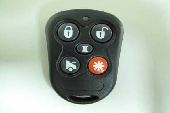
Bluetooth speaker
Equipment Class
DSS - Part 15 Spread Spectrum TransmitterBluetooth speaker
Equipment Class
DSS - Part 15 Spread Spectrum Transmitter
1-Way Remote Control
Equipment Class
DSC - Part 15 Security/Remote Control Transmitter