A5FEIA605MRFRF Modules for Battery Powered Smoke & Heat Alarms EiA600 Series
Ei Electronics Ltd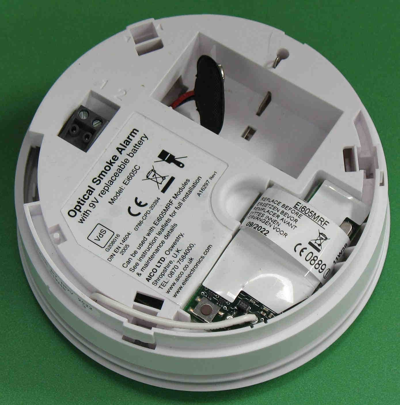
Click to zoom
Application Details
- Equipment Class
- DXX - Part 15 Low Power Communication Device Transmitter
- Date of Grant
- Apr 29, 2012
- Application Purpose
- Original Equipment
- Date of Application
- Apr 29, 2012
- Equipment Note
- RF Modules for Battery Powered Smoke & Heat Alarms EiA600 Series
- Frequency Range
- 902.50000000 - 902.50000000
- Company
- Ei Electronics Ltd
- Country
- Ireland
Documents & Files
Document Text
Text extracted from the exhibit documents filed with the FCC. Open a document above to read the original.
Users Manual
Instructions Read and retain carefully for as long as the product is being used. It contains vital information on the operation and installation of your Smoke Alarm. The leaflet should be regarded as part of the product. If you are just installing the unit, the leaftet must be given to the householder. The leaflet is to be given to any subsequent user. EiA605MRF Module RF Modules for Battery Powered Smoke & Heat Alarms EiA600 Series Introduction Congratulations on purchasing an EiA600 Series RF RadioLINK module. These RF modules can be easily installed in the EiA600 Series Alarm to provide you with an RF interconnected fire warning system – when one Alarm senses fire and sounds a warning, all the other Alarms will also sound a warning. This helps to ensure the alarm sound will be heard throughout the property. Installation 1. The EiA600 Series Alarm must be installed as per the guidance in the instruction booklet ‘Battery Powered Smoke & Heat Alarms’. 2. Remove the RF module from the packaging and using the pull tag, carefully insert into the back of the Alarm (see figure 1) - (some Alarm models may have the RF Module already fitted). 3. Ensure that the battery is connected. House code the Alarms as follows: 4. Before fitting the Alarm to the mounting plate, press and hold the ‘House Code’ switch on the rear of the RadioLINK module until the red light comes on (see Figures 2a) and then release. 5. Twist the Alarm onto its mounting plate. 6. Similarly press and hold the House Code switch on the second Alarm until its red light comes on and then release. Twist the Alarm onto its mounting plate. Put all the remaining alarms into House Code mode similarly and attach to the mounting plate in the same manner in less than 15 minutes. (They automatically exit house code mode after 30 minutes). 2 7. When in the House Code mode, the blue light (on the front of the Alarm - see figure 2b) will flash a number of times every 5 seconds to indicate: (a) that the Alarm is in House Code mode, and (b) the number of Alarms that have been identified and added to your system. For example with 3 Alarms in your system, you should see 3 blue light flashes every 5 seconds, with 4 Alarms in your system you should see 4 blue light flashes and so on, (with the 10th unit, the blue flash is longer, to help with the counting). Check that the number of blue light flashes corresponds to the number of Alarms in the system. If not see the “RadioLINK Troubleshooting” section below. 3 INSERT RF MODULE BY PLUGGING IN PINS & ALSO INSERT ITS ANTENNA IN THE HOLE PROVIDED - HOLD BY PULL TAG PULL TAG ANTENNA HOLE ANTENNA LED Figure 1 8. The Alarms will stay in House Code mode for 30 minutes and then reset automatically. Alternatively they can be taken out of House Code mode by removing one Alarm from its mounting plate and quickly pressing and holding the House Code switch until the red light comes on solidly again. Release the switch and the red light will go out immediately, indicating that the Alarm is no longer in House Code mode. Replace the Alarm on the mounting plate. The blue light will no longer be flashing. Note: As this Alarm exits house code mode it sends a radio message to all the other Alarms to exit the house code mode. Check that all the blue lights on the rest of the Alarms have ceased flashing. (Accessories must be taken out of house code manually - see their instructions). 9. Button test all Alarms in turn and check all the other Alarms are sounding at the same time. If they are not all communicating see section below “RadioLINK Troubleshooting”. 4 BLUE LIGHT RED LIGHT HOUSECODE SWITCH Figure 2a Figure 2b 5 Additional RadioLINK Alarms can be added to the system at any time. Simply put all the Alarms into the House Code mode at the same time and again check the number of blue light flashes on each Alarm. RadioLINK Troubleshooting It is imperative that all Alarms in your system communicate with each other. The number of walls, ceilings and metal objects in the signal path reduces the strength of the RadioLINK signals between the Alarms. Accordingly, one or more Smoke / Heat Alarms may have difficulties in communicating to all the other Alarms in the system. If, when checking the RadioLINK interconnection, some of the Alarms do not respond to the button test, then you will need to either: (i) Position another RadioLINK Alarm to act as a ‘repeater’ (see Interconnection with RadioLINK Modules below) between the units which are not communicating and so shorten the path and/or by-pass an obstacle which is blocking the signal. When the new Alarm is fitted, house code all Alarms again, as described above. (ii) For maximum RF signal strength orientate all the antennas in the same direction - see Figure 3. (iii) rotate / re-locate the units (e.g. move them away from metal surfaces or wiring). After making these changes to the RF signal path, the RadioLINK signals may still not be reaching all the Alarms in your system, even though they have already been House Coded successfully. (see Section on “RadioLINK Limitations”). It is important to check that all Alarms are communicating in their final installed positions. If Alarms are rotated, have had their antennas extended and/or resited, we would recommend that all the Alarms are returned to the factory settings and then House Coded again in their final positions (see above). The RadioLINK interconnection should then be checked again by button testing all units. (Note: The RadioLINK module can be returned to the originally factory settings by pressing and holding the House Code switch on until the red light turns on solidly and then flashes slowly. This will take about 10 seconds. This clears the House Codes that have been learnt). 6 Large hole nearest front wall Orientate all mounting plates in the same direction Front WallFront Wall Mounting PlateMounting Plate Mounting Plate Mounting Plate Figure 4 Interconnection with RadioLINK Modules A combined maximum of 18 Alarms (12 S…
Text truncated - open the document above for the full version.
External Photos
Front Side Back Side
ID Label/Location Info
P/N A17470 RevC EiA200MRF Replace before date: Remplacer avant: YYYY/MM FCCID: A5FEIA200MRF Replace before date: Remplacer avant: YYYY/MM FCCID: A5FEIA605MRF 38mm x 16mm EiA200MRF Labels P/N A17471 RevC EiA605MRF 38mm x 16mm EiA605MRF Labels Ei A605 MRF Series Label Location
Internal Photos
Component Side Back Side Showing Antenna Back Side Zoomed In
Test Report
This report is for the exclusive use of Intertek's Client and is provided pursuant to the agreement between Intertek and its Client. Intertek's responsibility and liability are limited to the terms and conditions of the agreement. Intertek assumes no liability to any party, other than to the Client in accordance with the agreement, for any loss, expense or damage occasioned by the use of this report. Only the Client is authorized to permit copying or distribution of this report and then only in its entirety. Any use of the Intertek name or one of its marks for the sale or advertisement of the tested material, product or service must first be approved in writing by Intertek. The observations and test results in this report are relevant only to the sample tested. This report by itself does not imply that the material, product, or service is or has ever been under an Intertek certification program. EMC Report for Ei Electronics on the EIA605MRF Module Page 1 of 20 731 Enterprise Drive Lexington, KY 40510 Telephone: 859-226-1000 Facsimile: 859-226-1040 www.intertek-etlsemko.com TEST REPORT Report Number: 100616101LEX-001 Project Number: G100616101 Report Issue Date: 3/9/2012 Product Name: EIA605MRF Module Model Number: EiA605MRF FCCID: FCCID TBD Industry Canada ID: ICID TBD FCC Standards: CFR Title 47 Part 15 Subpart C Industry Canada Standards: RSS-210 Issue 8 Tested by: Client: Intertek Testing Services NA, Inc. 731 Enterprise Drive Lexington, KY 40510 Ei Electronics Shannon Industrial Estate Shannon , Co. Clare Ireland Report prepared by Report reviewed by Bryan Taylor, Team Leader James Sudduth, Assistant Chief Engineer Intertek Report Number: 100616101LEX-001 Issued: 3/9/2012 EMC Report for Ei Electronics on the EIA605MRF Module FCCID:FCCID TBD Page 2 of 20 TABLE OF CONTENTS 1 Introduction and Conclusion .............................................................................................................. 3 2 Test Summary ...................................................................................................................................... 3 3 Description of Equipment Under Test ............................................................................................... 4 4 Occupied Bandwidth ........................................................................................................................... 6 5 Radiated Spurious Emissions (Transmitter) ..................................................................................... 8 6 Radiated Spurious Emissions (Receiver)........................................................................................ 15 7 Antenna Requirement per FCC Part 15.203..................................................................................... 18 8 Measurement Uncertainty ................................................................................................................. 19 9 Revision History................................................................................................................................. 20 Intertek Report Number: 100616101LEX-001 Issued: 3/9/2012 EMC Report for Ei Electronics on the EIA605MRF Module FCCID:FCCID TBD Page 3 of 20 1 Introduction and Conclusion The tests indicated in section 2 were performed on the product constructed as described in Section 3. The remaining test sections are the verbatim text from the actual data sheets used during the investigation. These test sections include the test name, the specified test method, a list of the actual test equipment used, documentation photos, results and raw data. No additions, deviations, or exclusions have been made from the standard(s) unless specifically noted. Based on the results of our investigation, we have concluded the product tested complied with the requirements of the standard(s) indicated. The results obtained in this test report pertain only to the item(s) tested. All testing was performed at the Intertek office located at 731 Enterprise Drive, Lexington Kentucky, 40510. The radiated emission test site is a 10-meter semi-anechoic chamber. The chamber meets the characteristics of CISPR 16-1 and ANSI C63.4: 2009. For measurements, a remotely controlled flush- mount metal-top turntable is used to rotate the EUT a full 360 degrees. A remote controlled non- conductive antenna mast is used to scan the antenna height from one to four meters. The test site is listed with the FCC under Registration Number 485103. The test site is listed with Industry Canada under Site Number IC 2042M-1. 2 Test Summary Page Test full name FCC Reference IC Reference Result 6 Occupied Bandwidth § 15.215 RSS-GEN(4.6.1) Pass 8 Radiated Spurious Emissions (Transmitter) § 15.249(a)(c)(d)(e) RSS-210 (A2.9) Pass 15 Radiated Spurious Emissions (Receiver) § 15.109 RSS-Gen (7.2.3) Pass --- AC Powerline Conducted Emissions § 15.207 RSS-Gen (7.2.2) NA 1 18 Antenna Requirement per FCC Part 15.203 § 15.203 RSS-Gen (7.1.4) Pass 1 This test was not applicable since there were no connections to the AC mains. Intertek Report Number: 100616101LEX-001 Issued: 3/9/2012 EMC Report for Ei Electronics on the EIA605MRF Module FCCID:FCCID TBD Page 4 of 20 3 Description of Equipment Under Test Equipment Under Test Manufacturer Ei Electronics Model Number EiA605MRF Serial Number Sample 3 FCC Identifier FCCID TBD Receive Date 12/27/2012 Test Start Date 12/27/2011 Test End Date 2/10/2012 Device Received Condition Good Test Sample Type Production Frequency Band 902.5MHz Mode(s) of Operation Transmitting at 902.5MHz Transmission Control Hard coded onto sample Maximum Output Power 93.69dBuV/m at 3 Meters Antenna Type (15.203) Permanently connected wire. Power Supply 9V Battery Description of Equipment Under Test The EiA605MRF was an RF module that installs into EiA 600 series smoke and heat alarms. Operating modes of the EUT: No. Descriptions of EUT Exercising 1 Transmitting continuously. A fresh battery was used for all testing. 2 Receive / idle mode.…
Text truncated - open the document above for the full version.
Test Setup Photos
Test Setup (Front) Test Setup (Back)
Contact Information
Applicant
Eric Duignan(VP Business Development North America)
Test Firm
Intertek Testing Services NAJames Sudduth
Technical Specifications
| # | Rule Parts | Frequency Range | Power Output |
|---|---|---|---|
| 1 | 15C | 902.5 MHz - 902.5 MHz | - |
Other Applications from Ei Electronics Ltd
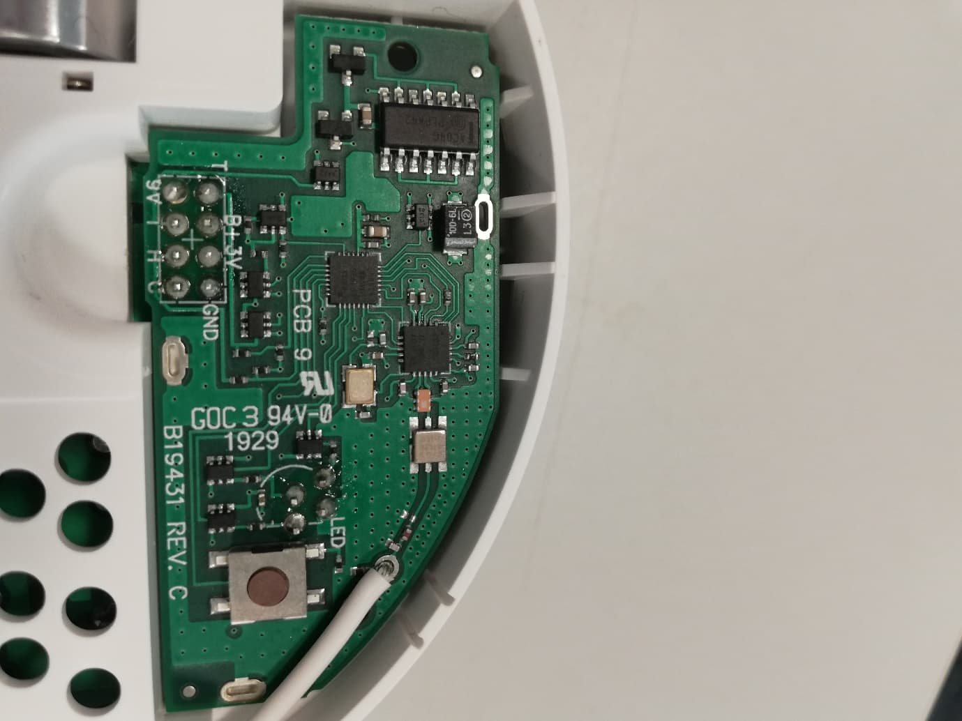
A5FEIA600MRF
Jun 02, 2020Ei Electronics RF Transceiver for EiA600 Series Smoke/Heat Alarms
Equipment Class
DXX - Part 15 Low Power Communication Device Transmitter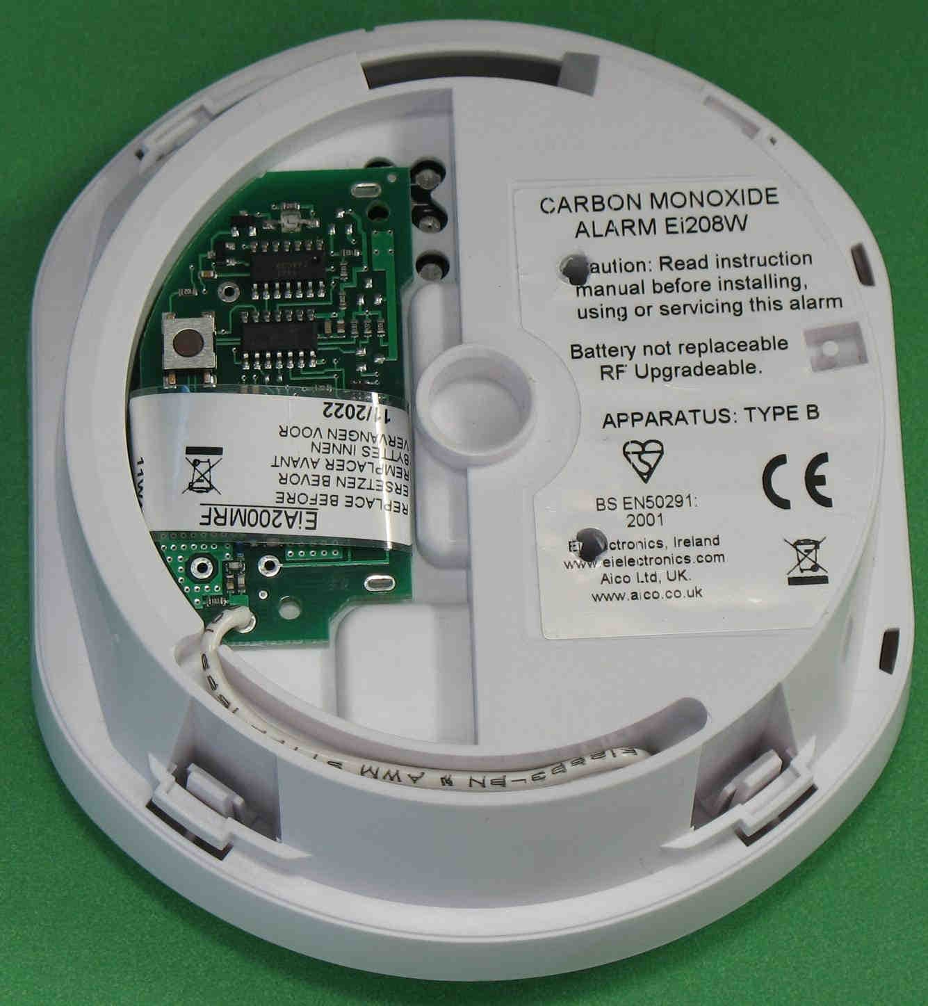
A5FEIA200MRF
Apr 29, 2012RF Module for Battery Carbon Monoxide Alarms Ei207 and Ei208
Equipment Class
DXX - Part 15 Low Power Communication Device Transmitter