A5G-Z60Fireplace Remote Control System
Avanti Hearth Products, LLC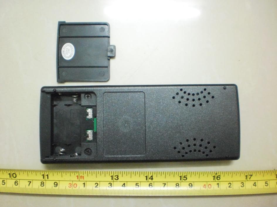
Click to zoom
Application Details
- Equipment Class
- DSC - Part 15 Security/Remote Control Transmitter
- Date of Grant
- Dec 07, 2011
- Application Purpose
- Original Equipment
- Date of Application
- Dec 07, 2011
- Equipment Note
- Fireplace Remote Control System
- Frequency Range
- 303.82500000 - 303.82500000
- Company
- Avanti Hearth Products, LLC
- Country
- United States
Documents & Files
Document Text
Text extracted from the exhibit documents filed with the FCC. Open a document above to read the original.
Users Manual
Avanti Hearth Products Z60 INSTALLATION AND OPERATING INSTRUCTION If you are unable to read or understand these instructions do not attempt to install or operate Please keep these Instructions for future reference. ☆ INTRODUCTION The Avanti Z60 thermal remote control system was developed with the latest radio frequency (RF) technology. The Avanti Z60 is easy to install. It allows the user to operate a gas appliance manually or thermostatically with a user-friendly remote control system which does not require any household electric current. The range of operation is approximately 20 feet (7 meters). The operating code of this remote control system has been pre-programmed for instant operation after installation. However, its special code-learning feature (on the receiver) allows the user to regulate the codes for operating with other transmitters for a maximum flexibility. Note: installation in metal cabinets may limit the range of operation ☆ COMPONENTS INCLUDED TRANSMITTER WALL-MOUNT COVERPLATE SLIDE BUTTONS WALL MOUNT BRACKET Description QTY Transmitter 1 “AAA” Batteries 2 Wall Mount Bracket (with Screws) 1 Receiver 1 “AA” Batteries 4 Wall Mount faceplate (with Screws) 1 7) Velcro at the bottom of the box Hearth Mount Slide knob (Black) 1 Wall Mount Slide knob (White) 1 Velcro 1 ☆ INSTALLING Z60 REMOTE SYSTEM (A) Getting the Transmitter Ready: 1. Installing Batteries The transmitter operates on 2 AAA-size 1.5V batteries. It is recommended that ALKALINE batteries always be used for longer battery life and maximum operational performance. Rechargeable batteries are not recommended. (1) Open the lid of the battery compartment on the back of the transmitter. (2) Insert 2 new or fully charged AAA-size 1.5V batteries into the battery compartment. Make sure the (+) and (-) ends of the batteries are correctly positioned as indicated on the casing. (3) When the batteries are installed, the LCD with similar numbers will display. + _ AAA + _ AAA Insert Batteries Note 1: On initial start up if a low battery indicator appears on the screen, you should either check the positions of the batteries or replace with new batteries. Note 2: It may take a few minutes (up to 15 minutes on a severe cold weather) for accurate room temperature readings to appear after the batteries have been installed. 2. LCD Display ① RF signal – Appears when signals are being emitted ② Thermostat Indicator – Thermo Off appears when it’s manually on; Thermo On appears when thermostat is activated. ③ Manual On/ Temp Set – ON shows when it’s manually turned on; set temperature shows when thermostat is in operation ④ Clock – Indicates the current time in AM/PM ⑤ Room – Indicates current room temperature ⑥ Flame – Indicates burner/ valve in operation ⑦ Battery – Battery power is low. Replace batteries within 2 weeks ⑧ Timer – Indicates time remaining before system shuts off when timer-programmed; 9-hour maximum setting ⑨ Lock – Childproof lock-out 3. Control Buttons ON/OFF UP TIMER/ CLOCK THERMOSTAT DOWN SET 3. Setting the Clock (1) Press and hold the “Timer/Clock” button for more than five seconds, the hour digit(s) will begin flashing. (2) Press the ▲ (UP) or ▼ (DOWN) button until the desired hour is displayed in AM or PM. (3) After setting the desired hour, push the “Timer/Clock” button again to set the minutes. The minute digits will begin flashing. (4) Press the ▲ (UP) or ▼ (DOWN) button until the desired minute is displayed. (5) Press the SET button, the minute digits will stop flashing, indicating the clock has been successfully set. Note: Flashing digits on LCD indicate the system is awaiting user’s input as mentioned above. The digits will stop flashing if no input is made within 10 seconds and the setting is automatically completed. 4. Setting °F / °C Scale The factory setting for temperature is °F(Fahrenheit). To change this setting to °C(Celsius): (1) Remove the battery cover on the back of the transmitter. F AM ROOM o F o C + _ AAA + _ AAA o F/ o C Switch (2) Adjust the temperature scale Dip Switch (on the left hand side, with °F/°C mark) with your fingernail or a ball pen point and move it to the °C scale on the right. To change from °C back to °F, move the dip switch back to °F again. 5. Operation Functions Note: The slide switch on the receiver must be placed in the REMOTE position for receiving commands from the transmitter. In other words, the transmitter (remote control) only works when the receiver is set in the REMOTE mode (Also refer to instructions in the RECEIVER section in this manual). To change the settings on the receiver, install the black knob on the receiver by pushing the knob gently on the control. (1) Turning ON/OFF the Fireplace: ○ 1 To turn the fireplace on, press the ψ(ON/OFF) button on the transmitter. The text ON and the flame icon will appear on the LCD. A thermo bulb and texts THERMO OFF are also seen on the LCD indicating the system is manually on but not thermostatically operating. ○ 2 Press the ψ(ON/OFF) button again to turn off the fireplace. The text ON, flame icon and thermo bulb will disappear from the LCD. (2) Setting Desired Temperature (THERMOSTAT): This remote control system can be thermostatically controlled by activating the THERMOSTAT (Auto) function from the transmitter: ○ 1 Press the ψ(ON/OFF) button to turn on the fireplace. The text ON, the flame icon, the thermo bulb and texts THERMO OFF will appear on the LCD. ○ 2 Press the AUTO button, the thermo bulb icon and texts THERMO ON will appear on the top row of LCD, the text ON will become THERMO TEMPERATURE. ○ 3 Press the ▲ (UP) or ▼ (DOWN) button to select the desired thermo temperature. The system will operate thermostatically as per your selected thermo temperature. THERMO ON F F AM THERMO SET ROOM Ã Thermo ON/Fireplace ON THERMO ON F F AM THERMO SET ROOM Ã Thermo ON/Fireplace OFF ● To disengage the THERMO function, press the AUTO button again, it will return to the manual ON mode. To completely turn off the fireplace, pr…
Text truncated - open the document above for the full version.
Cover Letter(s)
SCS-F18: Project and Product Certificat ion Representative Authorizat ion Letter Page 1 of 2 Rev 2.0 2206 Ringwood Avenue San Jose, CA 95131 Te l: 408-526-1188 Fa x: 408-526-1088 Ema il: T CB@sie mic.co m Project and Product Certification Representative Authorization Letter Reason for Amendment (current / obsolete) Revision History Approved Date From To I nitial Release (current) 1.0 1.0 Nov-14-2006 Revised wording (current) 1.0 2.0 Sept–25-2007 SCS-F18: Project and Product Certificat ion Representative Authorizat ion Letter Page 2 of 2 Rev 2.0 Avanti Hearth Products, LLC 2011-12-07 To: SIEMIC, INC. 2206 Ringwood Avenue, San Jose, CA 95131 USA Dear Sir/Madam, Re: Project and Product Certification Representative Authorization Letter We, Avanti Hearth Products, LLC hereby authorize SIEMIC, INC. to act as a Certification Body for certifying for the following project(s): (E.U.T): Fireplace Remote Control System (M/N):Z60 We affirm that between SIEMIC and Avanti Hearth Products, LLC any difference in understanding, including test plan, measurement methods, applicable standards and relevant procedures and processes have been resolved prior to commencement of testing activities. Sincerely, Client’s signature: Client’s name / title:LEI RUSHA Contact information / address:Avanti Hearth Products, LLC / 5932 WILKINSON BOULEVARD, BELMONT, NORTH CAROLINA 28012 USA
Cover Letter(s)
SCS-F19: Confidentia lity Request Letter Page 1 of 2 Rev 2.0 2206 Ringwood Avenue San Jose, CA 95131 Tel: 408-526-1188 Fa x: 408-526-1088 Ema il: TCB@sie mic.co m Confidentiality Request Letter Reason for Amendment (current / obsolete) Revision History Approved Date From To I nitial Release (current) 1.0 1.0 Nov-14-2006 Adding CFR 2.459 1.0 2.0 August – 11 - 2008 SCS-F19: Confidentia lity Request Letter Page 2 of 2 Rev 2.0 Avanti Hearth Products, LLC 2011-12-07 To: Federal Communications Commission Authorization and Evaluation Division 7435 Oakland Mills Road Columbia, MD Confidentiality Request regarding application for certification of FCC ID: A5G-Z60 We hereby request confidential treatment of information accompanying this application as outlined below: Block Diagram Schematic Diagram Operational Description The above materials contain trade secrets and proprietary information not customarily released to the public. The public disclosure of these materials may be harmful to the applicant and provide unjustified benefits to its competitors. The applicant understands that pursuant to Section 0.457 & 0.459 of the Rules, disclosure of this application and all accompanying documentation will not be made before the date of the Grant for this application. Sincerely, Client’s signature Client’s name / title : LEI RUSHA (Manager) Contact information / address: 5932 WILKINSON BOULEVARD, BELMONT, NORTH CAROLINA 28012 USA
External Photos
Appearance photograph of EUT Appearance photograph of EUT Appearance photograph of EUT Appearance photograph of EUT
ID Label/Location Info
FCC ID LABEL FCC ID: A5G-Z60 This device complies with Part 15 of the FCC Rules.Operation is subject to the following two conditions:1. This device may not cause harmful interference, and 2. This device must accept any interference received,including interference that may cause undesired ope ration. Label Location on EUT EUT Bottom View/ FCC ID Label Location
Internal Photos
Inside photograph of EUT Main PCB photograph of EUT antenna Main PCB photograph of EUT
Test Report
Shenzhen BCTC Technology Co., Ltd. Report No.: BCTC12070348E FCC ID: A5G-Z60 Page 1 FCC ID TEST REPORT FCC PART 15.231 for Fireplace Remote Control System MODEL: Z60 FCC ID: A5G-Z60 Test Report Number: BCTC12070348E Issued Date: December 07, 2011 Issued for Avanti Hearth Products, LLC 5932 WILKINSON BOULEVARD, BELMONT, NORTH CAROLINA 28012 USA Issued By: Shenzhen BCTC Technology Co., Ltd. B Building Room8518, Multiple Use Building of Economic Cooperative, Team one, Anle country, No. 44 of Xin’an Block, Bao’an Area, Shenzhen TEL: +86-755- 33865088 FAX: +86-755- 36933236 Note: This report shall not be reproduced except in full, without the written approval of Shenzhen BCTC Technology Co., Ltd. This document may be altered or revised by Shenzhen BCTC Technology Co., Ltd. personnel only, and shall be noted in the revision section of the document. The test results i n the report only apply to the tested sample. Shenzhen BCTC Technology Co., Ltd. Report No.: BCTC12070348E Page 2 of 22 FCC ID: A5G-Z60 Revision History Of Report Rev. Issue No. Revisions Effect Page Revised By 00 BCTC12070348E Initial Issue ALL Lisa Zhu Shenzhen BCTC Technology Co., Ltd. Report No.: BCTC12070348E Page 3 of 22 FCC ID: A5G-Z60 TABLE OF CONTENTS 1 TEST CERTIFICATION ......................................................................................................... 4 4 TEST METHODOLOGY ........................................................................................................ 7 4.1. DECISION OF FINAL TEST MODE ........................................................................................7 4.2. EUT SYSTEM OPERATION ...................................................................................................7 5 SETUP OF EQUIPMENT UNDER TEST ............................................................................ 8 5.1. DESCRIPTION OF SUPPORT UNITS....................................................................................8 5.2. CONFIGURATION OF SYSTEM UNDER TEST ....................................................................8 6 FACILITIES AND ACCREDITATIONS ............................................................................... 9 6.2 MEASUREMENT UNCERTAINTY ...................................................................................... 9 7 TEST REQUIREMENTS ........................................................................................................ 9 7.1. CONDUCTED EMISSION MEASUREMENT..........................................................................9 7.2. Radiation Emission Test ........................................................................................................12 7.3. 20B Bandwidth ....................................................................................................................16 7.4 DEACTIVATION TESTING ....................................................................................................18 7.5. Antenna requirement...........................................................................................................19 7.6 DUTY CYCLE .........................................................................................................................20 Shenzhen BCTC Technology Co., Ltd. Report No.: BCTC12070348E Page 4 of 22 FCC ID: A5G-Z60 1 TEST CERTIFICATION Product: Firepl ace Remote Cont rol System Model: Z60 Applicant: Avanti Hearth Products, LLC 5932 WILKINSON BOULEVARD, BELMONT, NORTH CAROLINA 28012 USA Factory: Micro Control Software Technology LTD Room 14021,Tianxin Plaza,89 East Jiefang Rd.Changsha,Hunan,C hina Trade Mark: Avanti Tested: Decem ber 01, 2011 - Decem ber 07, 2011 Test Voltage: DC 3V Battery Applicable Standards: FCC Part 15:Subpart C ANSI C63.4: 2003 The above equipment has been tested by Shenzhen BCTC Technology Co., Ltd. and found compliance with the requirements set forth in the technical standards mentioned above. The results of testing in this report apply only to the product/system, which was tested. Other similar equipment will not necessarily produce the same results due to production tolerance and measurement uncertainties. Tested By: Date: Decem ber 07, 2011 (Davis Ma) Check By: Date: Decem ber 07, 2011 (Merry Zhao) Approved By: Date: Decem ber 07, 2011 (Lisa Zhu) Shenzhen BCTC Technology Co., Ltd. Report No.: BCTC12070348E Page 5 of 22 FCC ID: A5G-Z60 2 TEST RESULT SUMMARY FCC 15 Subpart C,Paragraph 15.231 Test Standards Test Items Test Results §15.231 Conducted test N/A §15.231 (b) Radiated Emission Pass §15.231 (c) 20dB Band Width Testing Pass §15.231 (a) Deactivation Testing Pass §15.203 ANTENNA REQUIREMENT Pass §15.231 DUTY CYCLE Pass Note: 1. The test result judgment is decided by the limit of test standard 2. The information of measurement uncertainty is available upon the customer’s request. 3. “N/A” means “Not applicable.” Shenzhen BCTC Technology Co., Ltd. Report No.: BCTC12070348E Page 6 of 22 FCC ID: A5G-Z60 3 EUT DESC RIPTION Product Fireplace Remote Control System Trade Mark Avanti Model Z60 Applicant Avanti Hearth Products, LLC Serial Number N/A Antenna Type PCB Antenna EUT Power Rating DC 3V Battery Temperature Range(Operating) +15 ~+ 35°C Operating Frequency 303.825MHz Note: N/A stand for no applicable. Models difference N/A Shenzhen BCTC Technology Co., Ltd. Report No.: BCTC12070348E Page 7 of 22 FCC ID: A5G-Z60 4 TEST METHODOLOGY 4.1. DECISION OF FINAL TEST MODE The EUT was tested together with the below additional components, and configuration, which produced the worst emission levels, was selected and recorded in this report. The measurement was performed at 3 axis for lie orientation, side orientation and stand orientation. The lie orientation is the worst mode, so only the worst mode test data was reported. The following test mode was recorder i n this report. Test item Test mode Conducted emission Test N/A Radiation Emission Test TRANSMITTING 20dB Band Width Testing TRANSMITTING Deactivat ion Testing TRANSMITTING 4…
Text truncated - open the document above for the full version.
Test Setup Photos
RADIATED EMISSION TEST
Contact Information
Applicant
Ru Sha Lei
Test Firm
emitel (Shenzhen) LimitedLouis Lin
Technical Specifications
| # | Rule Parts | Frequency Range | Power Output |
|---|---|---|---|
| 1 | 15.231 | 303.825 MHz - 303.825 MHz | - |