A64-CP-501RTLS Locator
Tempsys
Click to zoom
Application Details
- Equipment Class
- DXT - Part 15 Low Power Transceiver, Rx Verified
- Date of Grant
- Feb 15, 2012
- Application Purpose
- Original Equipment
- Date of Application
- Feb 02, 2012
- Equipment Note
- RTLS Locator
- Frequency Range
- 903.00000000 - 927.00000000
- Company
- Tempsys
- Country
- United States
Documents & Files
Document Text
Text extracted from the exhibit documents filed with the FCC. Open a document above to read the original.
Users Manual
RTLS User Guide General Description The Tempsys Real Time Location Services (RTLS) system consists of two device types to remotely monitor various assets and determine their location within a facility. Data is sent to a central database for formal presentation and reporting. Tag devices are place on each asset to be managed, while Locators are placed in each room or area where assets are expected to be. The system operates in the 865MHz (Europe/Asia) and 915Mhz (US) ISM bands using off-the- shelf FSK RFIC radios. The Tags are low power devices that transmit on a fixed set of frequencies, while the Locator operates as a Frequency Hopper over 60 narrow band frequency channels. Data from Tags are received by Locators and then forwarded to the Tempsys Temperature System radio backbone which consists of either Repeaters or Access Points. A complete system consists of the two RTLS products, plus radio infrastructure hardware (Repeaters and Access Points), as well as a PC Server running the Tempsys Location engine. The Location engine interfaces to a number of 3rd party software tools that provides a user friendly front end to manage the various Assets in the system. • Location Engine running on a PC server • A variable number of Repeaters and Access Points to forward RTLS data to the Location Engine. • A variable number of Tag units, each with a CR2032 battery • A variable number of Locator units, each with four D cell batteries. Warning Installation Tool You should have received a copy of the Tempsys RTLS Setup Tool. This runs on a Windows based PC and provides a basic interface into the Location Engine, suitable for setting up the system and assigning Tag serial numbers to the Assets being tracked. More detailed information can be found in the separate manual for that software. NOTE: THE MANUFACTURER IS NOT RESPONSIBLE FOR ANY RADIO OR TV INTERFERENCE CAUSED BY UNAUTHORIZED MODIFICATIONS TO THIS EQUIPMENT. SUCH MODIFICATIONS COULD VOID THE USER’S AUTHORITY TO OPERATE THE EQUIPMENT Wireless Monitoring Solution by TempSys Tag Configuration The Tag units do not require any setup or configuration. They will have a serial number assigned to their bracket and this number needs to be associated with the Asset serial number using the RTLS Setup tool. Locator Configuration Locator units also do not require any setup or configuration. Their functionality can be changed by using ordering a different BracketID feature from the factory. Regular Locators are suitable for covering a single room with low traffic or Assets. Special High Density Locators are used for high traffic areas such as operating rooms where dozens of Assets could be located. Up to four High Density Locators can be placed in a single room. Usage Assuming the Location Engine server has previously been setup and Access Point installed throughout the site, the user will start the RTLS Setup program on a local PC and connect to the Location Engine server. Both Tags and Locators will come with Batteries installed. To turn on either device, press and hold the button near the LED window until the LED starts to flash. It will flash slowly at first, then rapidly flash when a Access Point beacons are seen, then finally illuminates for 10 seconds when it successfully communicates with the network. Button Usage When a unit is off, press and hold for three or four seconds to turn on. LED starts to flash When unit is on, press and hold for three or four seconds to turn off. LED will be off A single press can indicate the state of the unit Constant on LED for 10 seconds means unit successfully communicating to network Single LED flash indicates the unit is on but not communicating with the network Double LED flash indicates the unit is OFF A double press when the unit is on and Connected will trigger an immediate data transmission Device Placement Locator devices should be placed on the wall or hung from the ceiling. If placed on the wall, it should be on the longer wall of the rectangular room, toward the center and at least 6 feet high. The front grill should be pointing down toward the floor. If placed on the ceiling, it should be again be located near the center of the longer wall, and with the grill pointing down toward the center of the room. Wireless Monitoring Solution by TempSys Tag devices are to be placed on the Asset, ideally with the grill part pointing up to the ceiling. The placement should be chosen so as not to block the ultrasound signal emanating from the grill area, but also in an area that is less accessible to patients and non-maintenance users of the equipment. Notes THIS DEVICE COMPLIES WITH PART 15 OF THE FCC RULES. OPERATION IS SUBJECT TO THE FOLLOWING TWO CONDITIONS: (1)THIS DEVICE MAY NOT CAUSE HARMFUL INTERFERENCE, AND (2)THIS DEVICE MUST ACCEPT ANY INTERFERENCE RECEIVED, INCLUDING INTERFERENCE THAT MAY CAUSE UNDESIRED OPERATION. Wireless Monitoring Solution by TempSys
Cover Letter(s)
Checkpoint® WirelessMonitoringSolutionbyTempSys 11/03/2011 FederalCommunicationsCommission EquipmentAuthorizationBranch 7435OaklandMillsRoad Columbia,MD21046 RequestforConfidentiality Companyname:TempSys,Inc. FCCID:A64-CP-501 FCCPart15Certification Gentlemen, Pursuantto47CFR0.457(d)(1)(ii)and0.459,TempSys,Inc.herebyrequests permanentconfidentiality ofthefollowingattachmentsforthesubjectapplication: ExhibitType FileName Description SchematicDrawingsCP-501Schematic.pdf SchematicDrawing OperationalDescription CP-501Operation.pdf OperationalDescription Thesedocumentscontaindetailedsystemandequipmentdescriptionandrelated information abouttheproductthatTempsysconsiderstobeproprietary, confidentialandacustomdesignandotherwisewouldnotreleasetothegeneral public.Sincethedesignis abasisfromwhichfuturetechnologicalproductswill evolve,Tempsysconsidersthatthisinformationwouldbeofbenefittoits competitorsandthatthedisclosureoftheinformationinthesedocumentswould givecompetitorsanunfairadvantageinthemarket. Sincerely, Robert/fuan President, TempSys,Inc 5701 HollisStreet,EmeryvilleCA94608•510-526-7624•Fax415-284-9288infoO.tempsvs.net www.tempsys.net
External Photos
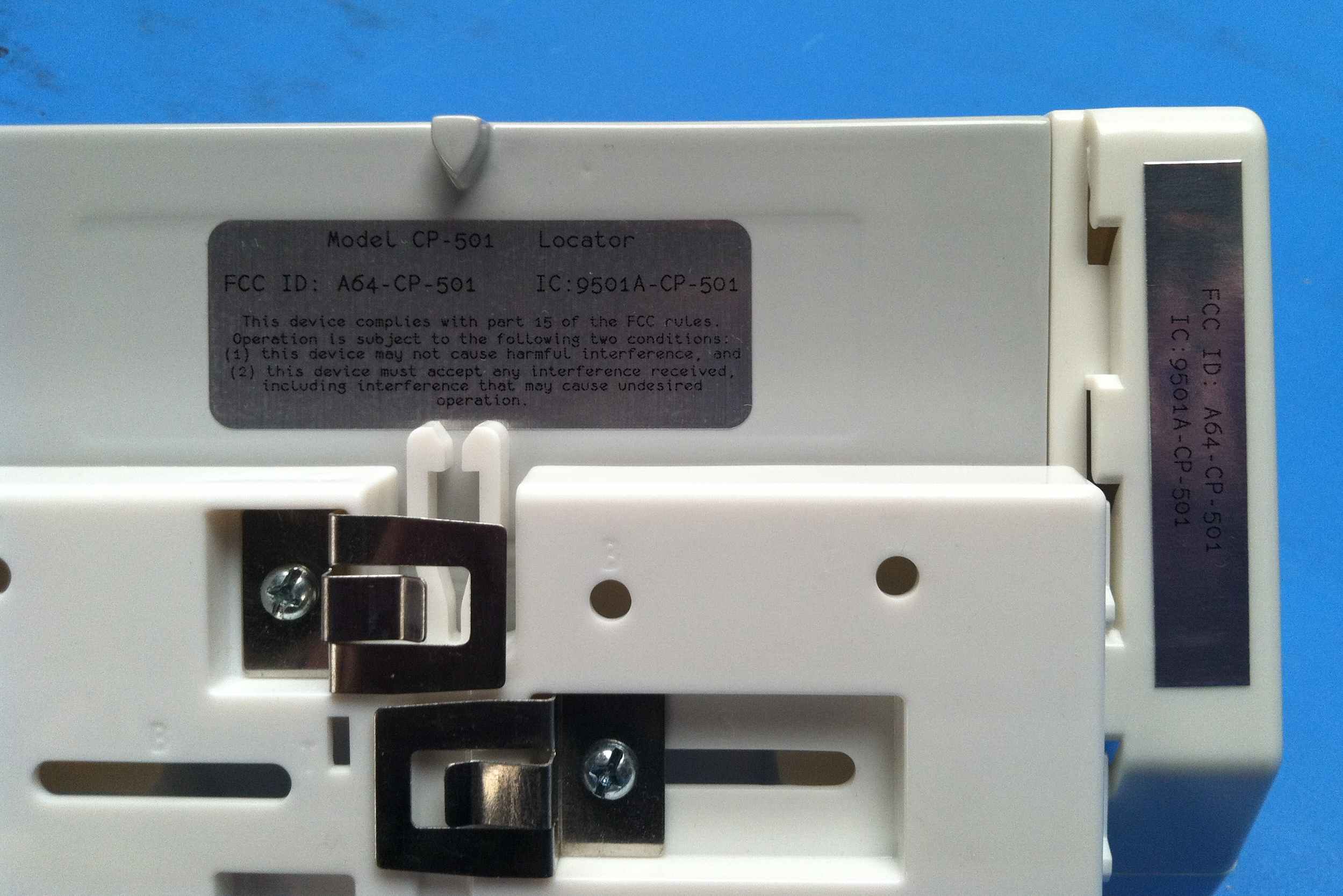
MiCOM Labs, 440 Boulder Court, Suite 200, Pleasanton, CA 94566 Tel: +1 (925) 462-0304, Fax: +1 (925) 462-0306, Web: www.micomlabs.com the wireless lab 2 February 2012 Tempsys External Photos CP-501 Page 2 of 4 the wireless lab Bottom view Page 3 of 4 the wireless lab Side view Page 4 of 4 the wireless lab Top view
Internal Photos
MiCOM Labs, 440 Boulder Court, Suite 200, Pleasanton, CA 94566 Tel: +1 (925) 462-0304, Fax: +1 (925) 462-0306, Web: www.micomlabs.com the wireless lab 2 February 2012 Tempsys Internal Photographs Model: CP-501 Installation view Page 2 of 3 the wireless lab Main Assy Front Page 3 of 3 the wireless lab Main Assy back
Test Report
Test of Tempsys CP-501 To: FCC 47 CFR Part15.247 & IC RSS-210 Test Report Serial No.: TEHA02-U3 Rev A TITLE PAGE TEST REPORT FROM Test of Tempsys CP-501 To FCC 47 CFR Part15.247 & IC RSS-210 Test Report Serial No.: TEHA02-U3 Rev A This report supersedes: None Manufacturer: Tempsys 5701 Holl is Street, CA Emeryville California 94608, USA Product Function: 915 MHz FHSS Copy No: pdf Issue Date: 31st January 2012 MiCOM Labs is an ISO 17025 Accredited Testing Laboratory CERTIFICATE #2381.01 This Test Report is Issued Under the Authority of; MiCOM Labs, Inc. 440 Boulder Cour t, Suite 200 Pleasanton, CA 94566 USA Phone: +1 (925) 462-0304 Fax: +1 (92 5) 462-0306 www.micomlabs.com This test report may be reproduced in full only. The document may only be updated by MiCOM Labs personnel. Any changes will be noted in the Document History section of the report. Title: Tempsys CP-501 To: Serial #: Issue Date: Page: FCC 47 CFR Part15.247 & IC RSS-210 TEHA02-U3 Rev A 31st January 2012 3 of 66 This test report may be reproduced in full only. The document may only be updated by MiCOM Labs p ersonnel. Any changes will be noted in the Document History section of the report. MiCOM Labs, 440 Boulder Court, Suite 200, Pleasanton, CA 94566 USA, Phone: 925.462.0304, Fax: 925.462.0306, www.micomlabs.com This page has been left intentionally blank Title: Tempsys CP-501 To: Serial #: Issue Date: Page: FCC 47 CFR Part15.247 & IC RSS-210 TEHA02-U3 Rev A 31st January 2012 4 of 66 This test report may be reproduced in full only. The document may only be updated by MiCOM Labs p ersonnel. Any changes will be noted in the Document History section of the report. MiCOM Labs, 440 Boulder Court, Suite 200, Pleasanton, CA 94566 USA, Phone: 925.462.0304, Fax: 925.462.0306, www.micomlabs.com TABLE OF CONTENTS ACCREDITATION & LISTINGS.......................................................................................5 RECOGNITION................................................................................................................ 6 PRODUCT CERTIFICATION........................................................................................... 7 1. .................................................................................9 TEST RESULT CERTIFICATE 2. ......................................10 REFERENCES AND MEASUREMENT UNCERTAINTY 2.1. .......................................................................................... 10 Normative References 2.2. ......................................................................... 10 Test and Uncertainty Procedures 3. ........................................11 PRODUCT DETAILS AND TEST CONFIGURATIONS 3.1. .................................................................................................. 11 Technical Details 3.2. ......................................................................................... 12 Scope of Test Program 3.3. .......................................................... 14 Equipment Model(s) and Serial Number(s) 3.4. .................................................................................................... 14 Antenna Details 3.5. ........................................................................................... 14 Cabling and I/O Ports 3.6. ............................................................................................... 15 Test Configurations 3.7. ....................................................................................... 15 Equipment Modifications 3.8. ....................................................................... 15 Deviations from the Test Standard 3.9. .......................................................... 15 Subcontracted Testing or Third Party Data 4. ....................................................................................................16 TEST SUMMARY 5. ......................................................................................................18 TEST RESULTS 5.1. .......................................................................................... 18 Device Characteristics 5.1.1. ....................................................................................... 18 20 dB Bandwidth 5.1.2. ............................................... 28 Transmitter Channels - Channel Spacing 5.1.3. ................................................................................ 31 Transmitter Channels 5.1.4. ............................................................................................ 36 Output Power 5.1.5. ............................................................... 39 Maximum Permissible Exposure 5.1.6. ............................................. 40 Conducted Spurious Emissions Transmitter 5.1.7. ................................................ 47 Conducted Spurious Emissions Stand-By 5.1.8. .................................................................................. 51 Radiated Emissions 5.1.9. .......................... 60 AC Wireline Conducted Emissions (150 kHz – 30 MHz) 6. .....................................................................................................62 PHOTOGRAPHS 6.1. ...................................................................... 62 General Measurement Test Set-Up 6.2. ................................................................................. 63 Radiated Emissions >1 GHz 6.3. ................................................................................. 64 Radiated Emissions <1 GHz 7. .................................................................................65 TEST EQUIPMENT DETAILS Title: Tempsys CP-501 To: Serial #: Issue Date: Page: FCC 47 CFR Part15.247 & IC RSS-210 TEHA02-U3 Rev A 31st January 2012 5 of 66 This test report may be reproduced in full only. The document may only be updated by MiCOM Labs p ersonnel. Any changes will be noted in the Document History section of the report. MiCOM Labs, 440 Boulder Court, Suite 200, Pleasanton, CA 94566 USA, Phone: 925.462.030…
Text truncated - open the document above for the full version.
Test Setup Photos
MiCOM Labs, 440 Boulder Court, Suite 200, Pleasanton, CA 94566 Tel: +1 (925) 462-0304, Fax: +1 (925) 462-0306, Web: www.micomlabs.com the wireless lab 2 February 2012 Test Setup Photographs Model: CP 501 General Measurement Test Set-Up Page 2 of 3 the wireless lab Radiated Emissions >1 GHz Page 3 of 3 the wireless lab Radiated Emissions <1 GHz
Contact Information
Applicant
Michael Plummer
Test Firm
Micom LabsGordon Hurst
Technical Specifications
| # | Rule Parts | Frequency Range | Power Output |
|---|---|---|---|
| 1 | 15C | 903 MHz - 927 MHz | 9.00 mW |
Other Applications from Tempsys

A64-CP-500
Feb 15, 2012Asset Tag
Equipment Class
DXT - Part 15 Low Power Transceiver, Rx Verified