A6E-GT15Remote Controller
Zhejiang Feishen Vehicle Co., LTD.
Click to zoom
Application Details
- Equipment Class
- DSS - Part 15 Spread Spectrum Transmitter
- Date of Grant
- May 18, 2020
- Application Purpose
- Original Equipment
- Date of Application
- May 18, 2020
- Equipment Note
- Remote Controller
- Frequency Range
- 2405.00000000 - 2478.00000000
- Country
- China
Documents & Files
Document Text
Text extracted from the exhibit documents filed with the FCC. Open a document above to read the original.
Users Manual
GT15 4CH 2.4GHzradio systeminstruction manual Product introduction GT15 is a multi-function 2.4GHz radio system. It contains a GT15T 4CH transmitter and a receiver. The receiver is optional. One is the standard 4-channel receiver GT15R, and the other is the 2+2 receiver GT15RD with built-in LED controller and winch motor controller. The GT15 is a simple, easy-to-use radio system that is ideal for vehicle models and ship models. Product specifications Transmitter model:GT15 Channel number:2p roportional channels +1 three-stage switch channel +1 two-stage-swit ch channel Voltage :DC 6V Transmitter frequency:2.4G(FHSS) Modulation:FSK Transmit power:16dBm (Conducted) Remote control distance:>120m Power supply:4cell AA batteries Knob:Knob Configuration mode:160X84X220mm Weight:230g(Wi thout batteries) Receiver Model:GT15R Channel number:4 channels(standard PWM output) Voltage range:4-6.5V Waterproof level:IP67 Interface:Futaba,JR Size:33 X 22 X 13mm Weight:5g GT15 transmitter GT15T transmitter function GT15T is a 4 channels transmitter which including steering channel, throttle channel, AUX1 button channel and AUX2 3-stage switch channel. The TH-TRIM, ST-TRIM, TH-DR, ST-DR, TH-REV, ST-REV, TH-EPA and ST-EPA functions can be set. The transmitter LED has power display and alarm function, and TRIM, DR, EPA adjustment status display function. GT15R receiver function The standard receiver GT15R has 4 channels standard PWM output, corresponding to ST, TH, AUX1, AUX2; GT15R has FAILSAFE function. GT15RD receiver function The 2+2 receiver GT15RD has 2 channels standard PWM output, 1 channel LED controller and 1 channel winch motor forward and reverse controller. GT15RD has FAILSAFE function. Installingthe transmitter batteries Power display LED1/2/3/4/5 : 100% Power LED1/2/3/4: 80% P ower LED1/2/3: 60% P ower LED1/2: 40% P ower LED1: 20% P ower Low voltage alarm LED1/2/3/4/5 -LED1/2/3/4-LED1/2/3-LED1/2-LED1-LED1-5 FLASH, cycle loop! GT15R receiver GT15RD receiver Remarks(Justfor GT15RD) LED Light Port: The AUX1 channel can directly control the Light Port. The VCC pin integrates a 200-ohm current limiting resistor to prevent the LED light from being burned when the external LED is directly connected. Winch motor Port: The AUX2 channel directly controls the output of thewinch motor port, where M+M- is connected to the positive and negative terminals of the winch motor. Users control the forward and reverse rotation of the motor through the three-stage switch of AUX2. The built-in motor driver has a maximum current of 3A. Binding: STEP1: Plug in the binding wire,then power on. The LED of the receiver will flash rapidly, indicating that it enters the binding mode and waits for the binding. STEP2: Press the BIND key of the transmitter, then power on the transmitter. The transmitter will enter the binding mode. LED1-5 will cycle in turn. STEP3: After the binding is successful, the receiver LED is always on. The transmitter exits the binding mode after 5 seconds, and the LEDs display the battery level. Receiver LED status: 1、 When the receiver receives the correct transmitter data, the LED light is always on. 2、 After the receiver is turned on, the LED will be off after 1 second, indicating that the receiver has not received the data of the transmitter. Please check whether the transmitter is turned on, or whether it has been bound. 3、 The LED flash rapidly, indicating the receiver enters the binding mode. 4、 The slow flashing of the receiver LED indicates that the receiver is in the disconnected state. FAILSAFE: The ST and TH channels of the receiver have FAILSAFE function. The FAILSAFE output of ST and TH can be set as follows: 1、 Turn on the transmitter and receiver to let them in normal communication. 2、 Adjust the transmitter's TH and ST to the position of the output when the communication is failed and keep it. 3、 Plug in the bindingwire into the bind port of the receiver. After the receiver LED flashes 2 times, unplug the bindingwire to finish the FAILSAFE setting. CHANNEL REVERSING: If the steering command causes the wheel to be in the opposite direction, the steering channel need to bereversed. If the throttle command causes the vehicle to travel in the opposite direction, the throttle channel need to be reversed. To reverse a channel, switch the correlating reverse switch. “N” is for normal, “R” is for reverse. DR SETTINGS The ST-DR knob is able to symmetrically adjust the direction travel. The TH-DR knob is able to symmetrically adjust the throttle travel. When adjusting DR, the LED light will show the value of the adjusted potentiometer. 5 seconds after the adjustment, the LED light will change back to the state of indicating power. As shown in figure: STEERING TRIM The ST-TR IM knob is used to adjust the trim of the steering so that the wheel is centered and the vehicle tracks straight. When ST-TRIM is adjusted, the LED light will show the adjustment. 5 seconds after the adjustment, the LED light will change back to the state of indicating power. As shown in figure: THROTTLE TRIM The TH-T RIM knob is used to adjust the throttle trim when the throttle stick is at neutral position. It is typically used to adjust the brakes. When TH-TRIM is adjusted, the LED light will show the adjustment. 5 seconds after the adjustment, the LED light will change back to the state of indicating power. As shown in fig ure: EPA SETTINGS The EPA function can adjust the travel of the ST and TH channels in each direction precisely. 1. Hold the throttle trigger in the full brake position and press the AUX1 button while powering on the transmitter. The middle LED(LED3) will flash, indicating the transmitter enters the EPA settings mode. 2. Throttle EPA: Hold the throttle trigger in full throttle position. Rotate the TH TRIM knob to adjust the full throttle end point,LED1-5 will display the value of the current Throttle EPA. Return the throttle trigger to the center position to exit and save the throttle EPA setting,…
Text truncated - open the document above for the full version.
Cover Letter(s)
Company: Zhejiang Feishen Vehicle Co., LTD. Add: North Lake Road Hardware Science And Technology In ZheJiang Province, Yong Kang, 321300 China Tel: 86-579-87297896 Fax: 86-579-87295396 DECLARATION Date: 2020 -03-27 To: FEDERAL COMMUNICATIONS COMMISSION Authorization and Evaluation Division 7435 Oakland Mills Road Columbia, MD 21046 Dear Sir or Madam: We, Zhejiang Feishen Vehicle Co., LTD. hereby declare that product name: Remote Controller (model name: GT15, 511946, 511948, 511949. FCC ID: A6E-GT15) These models are electrically identical with the PCB design, components and electromagnetic compatibility characteristics, and model: GT15 has been tested by BACL. The differences of them are as follows: Model name Please contact me if there is need for any additional clarification or informat ion. Best Regards, Signature: Typed or Printed Name: JianFeng Ding Title: Manager
Cover Letter(s)
QA-FR-170-B Company: Zhejiang Feishen Vehicle Co., LTD. Add: North Lake Road Hardware Science And Technology In Zh eJiang Province, Yong Kang, 321300 China Tel: 86-579-87297896 Fax: 86-579-87295396 FCC Authorization Date: 2020-03-27 FE DERAL COMMUNICATIONS COMMISSION Authorization and Evaluation Division 7435 Oakland Mills Road Columbia, MD 21046 Subject: Agent Authorization To whom it may concern: We, Zhejiang Feishen Vehicle Co., LTD., the undersigned, Hereby authorizes Bay Area Compliance Laboratories Corporation to act on its behalf in all matters relating to application for Equipment authorization, including the signing of all documents relating to these matters. All acts carried ou t by Bay Area Compliance Laboratories Corp. on our behalf shall have the same effect as our own action. We, the undersigned, hereby certify that we are not subject to a denial of federal benefits, that includes FCC benefits, pursuant to Section 5301 of the Anti-Drug Abuse Act of 1988, 21 U.S.C. 862. This authorization is valid until further written notice from the applicant. Sincerely Yours, Signature: Typed or Printed Name: JianFen g Ding Title: Manager
Cover Letter(s)
Co mpany: Zhejiang Feishen Vehicle Co., LTD. Add: North Lake Road Hardware Science And Technology In ZheJiang Province, Yong Kang, 321300 China Tel: 86-5 79-87297896 Fax: 86-5 79-87295396 E-mail: [email protected] FCC Confidential Authorization Date: 2020-03-27 FEDERAL COMMUNICATIONS COMMISSIONS Authorization and Evaluation Division 7435 Oakland Mills Road Columbia, MD 21046 Subject: Confidentiality Request regarding application for certification of FCC ID: A6E-GT15 To: whom it may concern, In accordance with Sections 0.457 and 0.459 of the Commission’s Rules, Zhejiang Feishen Vehicle Co ., LTD. hereby requests long-term confidential treatment of information accompanying this application as outlined below: Block Diagram Schematics Operation Description The above materials contain proprietary and confidential information not customarily released to the public. The public disclosure of these materials provides unjustified benefits to its competitors in the market. Sincerely Yours, Sig nature: Typed or Printed Name: JianFeng Ding Title: Manager
External Photos
EXHIBIT A - EUT EXTERNAL PHOTOGRAPHS
Internal Photos
EXHIBIT B - EUT INTERNAL PHOTOGRAPHS TX Antenna
Test Report
Note: This test report is prepared for the customer shown above and for the device described herein. It may not be duplicated or used in part without prior written consent from Bay Area Compliance Laboratories Corp. This report is valid only with a valid digital signature. The digital signature may be available only under the Adobe software above version 7.0. FCC PART 15.247 TEST REPORT For Zhejiang Feishen Vehicle Co., LTD. North Lake Road Hardware Science And Technology In ZheJiang Province, Yong Kang, 321300 China FCC ID: A6E-GT15 Report Type: Original Report Product Type: Remote Controller Test Engineer: Chris Wan g Re port Number: RSHD200327002-00A Re port Date: 2020-05-11 Reviewed B y: Oscar Ye EMC Manager Prepared By: Bay Area Compliance Laboratories Corp. (Kunshan) No.248 Chenghu Road,Kunshan,Jiangsu province,China Tel: +86-0512-86175000 Fax: +86-0512-88934268 www.baclcorp.com.cn Bay Area Compliance Laboratories Corp. (Kunshan) Report No.: RSHD200327002-00A FCC Part 15.247 Page 2 of 42 TABLE OF CONTENTS GENERAL INFORMATION ....................................................................................................................................... 4 PRODUCT DESCRIPTION FOR EQUIPMENT UNDER TEST (EUT) ..................................................................................... 4 OBJECTIVE ................................................................................................................................................................... 4 RELATED SUBMITTAL(S)/GRANT(S) ............................................................................................................................. 4 TEST METHODOLOGY .................................................................................................................................................. 5 MEASUREMENT UNCERTAINTY .................................................................................................................................... 5 TEST FACILITY ............................................................................................................................................................. 5 SYSTEM TEST CONFIGURATION .......................................................................................................................... 6 DESCRIPTION OF TEST CONFIGURATION ...................................................................................................................... 6 EUT EXERCISE SOFTWARE .......................................................................................................................................... 6 SPECIAL ACCESSORIES ................................................................................................................................................. 6 EQUIPMENT MODIFICATIONS ....................................................................................................................................... 7 SUPPORT EQUIPMENT LIST AND DETAILS .................................................................................................................... 7 EXTERNAL I/O CABLE .................................................................................................................................................. 7 BLOCK DIAGRAM OF TEST SETUP ................................................................................................................................ 7 SUMMARY OF TEST RESULTS ............................................................................................................................. 10 TEST EQUIPMENT LIST ......................................................................................................................................... 11 FCC§15.247 (i), §1.1310 &§2.1093 – RF EXPOSURE ............................................................................................. 12 MEASUREMENT RESULT ............................................................................................................................................ 12 FCC §15.203 – ANTENNA REQUIREMENT .......................................................................................................... 13 APPLICABLE STANDARD ............................................................................................................................................ 13 ANTENNA CONNECTOR CONSTRUCTION .................................................................................................................... 13 FCC §15.207 (a) – AC LINE CONDUCTED EMISSIONS ..................................................................................... 14 APPLICABLE STANDARD ............................................................................................................................................ 14 EUT SETUP ................................................................................................................................................................ 14 EMI TEST RECEIVER SETUP ....................................................................................................................................... 14 TEST PROCEDURE ...................................................................................................................................................... 15 FACTOR & OVER LIMIT CALCULATION ...................................................................................................................... 15 TEST RESULTS SUMMARY .......................................................................................................................................... 15 TEST DATA ................................................................................................................................................................ 15 FCC §15.205, §15.209 & §15.247(d) – RADIATED EMISSIONS ........................................................................... 18 APPLICABLE STANDARD .................................…
Text truncated - open the document above for the full version.
Test Setup Photos
EXHIBIT C - TEST SETUP PHOTOGRAPHS Conducted Emissions (Front View) Conducted Emissions (Side View) Radiated Emissions (Below 1GHz) Radiated Emissions (Above 1GHz)
Contact Information
Applicant
JianFeng Ding
Test Firm
Bay Area Compliance Laboratories Corp. (Kunshan)Mr. John Chan
[email protected]+86 0512 86175000
Technical Specifications
| # | Rule Parts | Frequency Range | Power Output |
|---|---|---|---|
| 1 | 15C | 2.40 GHz - 2.48 GHz | 36.00 mW |
Other Applications from Zhejiang Feishen Vehicle Co., LTD.

A6E-FSHTX
May 01, 2013QUADTRANSMITTER
Equipment Class
DXX - Part 15 Low Power Communication Device Transmitter
A6E-FSHRX
May 01, 2013QUADCOPTER
Equipment Class
DXX - Part 15 Low Power Communication Device Transmitter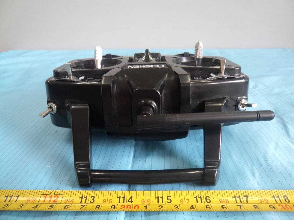
A6EZJFSH62832
Mar 08, 20122.4 GHz Digital Proportional R/C System
Equipment Class
DXT - Part 15 Low Power Transceiver, Rx Verified