A6GD4M35MD02MUNIC
MUNIC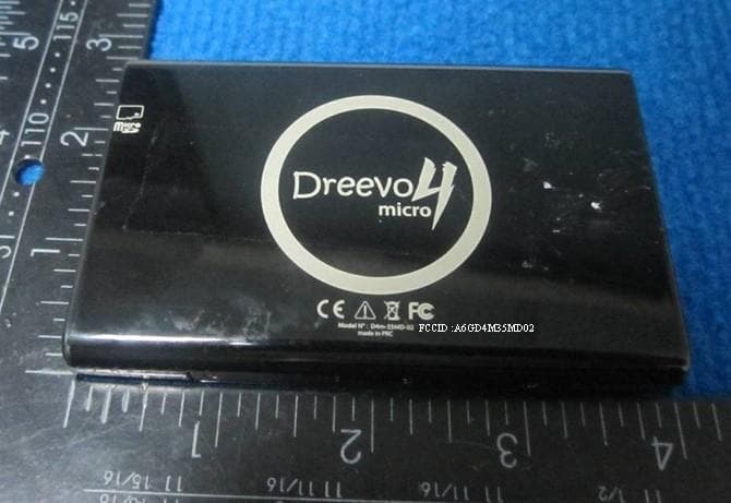
Click to zoom
Application Details
- Equipment Class
- PCB - PCS Licensed Transmitter
- Date of Grant
- Mar 05, 2012
- Application Purpose
- Original Equipment
- Date of Application
- Mar 05, 2012
- Equipment Note
- MUNIC
- Frequency Range
- 1850.20000000 - 1909.80000000
- Company
- MUNIC
- Country
- France
Documents & Files
Document Text
Text extracted from the exhibit documents filed with the FCC. Open a document above to read the original.
Users Manual
GENERAL VIEW TECH. SPECIFICATION Performance Processor Arm11 ‐ 500MHz Flash 4GB ‐ RAM 128 MB 3.5’’ LCD TFT 320x480 Resistive TP Power input voltage 5V DC – 2A max GSM Frequency bandwidth 850/1900 Working temperature ‐ 20°C / 60°C Internal battery 1000mAh Dimensions/Weight 100 x 63 x 14 mm / 110g Quick Start Guide CHARACTERISTICS GPS (Global Positioning System) GPRS Communication Bluetooth FM transmitter with car charger antenna Loud speaker Microphone 3D Accelerometer Micro SD card connector 1. Mini –USB Connecter 2. Micro SD card lector 3. Reset button 4. Speaker 5. Power button with LED indication 6. Alert information button 7. Up / Down button 8. Magnet support 9. Metal unit USAGE 1. With internal battery power supply, the LED power indication button is turned on after 15 seconds and MUNIC is self ‐ checking. 2. For first switch on MUNIC, you need to answer a few questions to set up it by tapping the screen. The device may need a few minutes to determine GPS position. 3. To planning a route, you just need tap “Navigate to” and enter the address. For your security, you should plan the route before driving. 4. To get the voice guiding or make phone call by MUNIC, you need to tap the screen and active the loud speaker, the micro will be active automatically. 5. To play spoken instructions or music through a Bluetooth device and FM transmitter, you have to connect the associated car charger then active the Bluetooth and FM transmitter, at the same time turn on the radio of your car. Once your radio finds MUNIC and the Bluetooth connection is established, the sound will be played through the radio on your car. 6. Changing between day color and night color can be automatic, or by tapping the menu. 7. To turn off the devices, push the power button for 15 seconds and confirm by tapping the screen. For customers in the United States This equipment has been tested and found to comply with the limits for a Class B digital device, pursuant to part 15 of the FCC Rules. These limits are designed to provide reasonable protection against harmful interference in a residential installation. This equipment generates uses and can radiate radio frequency energy and, if not installed and used in accordance with the instructions, may cause harmful interference to radio communications. However, there is no guarantee that interference will not occur in a particular installation. If this equipment does cause harmful interference to radio or television reception, which can be determined by turning the equipment off and on, the user is encouraged to try to correct the interference by one or more of the following measures: • Reorient or relocate the receiving antenna. • Increase the separation between the equipment and receiver. • Connect the equipment into an outlet on a circuit different from that to which the receiver is connected. • Consult the dealer or an experienced radio/TV technician for help. This device complies with Part 15 of the FCC Rules. Operation is subject to the following two conditions: 1. This device may not cause harmful interference. 2. This device must accept any interference received, including interference that may cause undesired operation. Caution Exposure to radio frequency radiation To comply with FCC RF exposure compliance requirements, this device must not be co ‐ located or operating in conjunction with any other antenna or transmitter. Please note the FM only can work with associated car charger. This FM function will be disable with other car charger. Note Caution: Any changes or modifications made on the system not expressly approved by the manufacturer could void the user's authority to operate the e q ui p ment. INSTALLATION 1. Using the Alcohol wet wipe to clean the console where you can to paste the magnet support. 2. Pasting the 3M side of magnet support on the cleaned console and pushing it strongly. 3. Do not touch the magnet during 5h, so it can be fixed very tightly. 4. Putting the MUNIC on the magnet support. 5. Connecting the associated car charger for FM transmitter NOTE. The FM transmitter only can work with associated car charger. This FM function should be disabling with other car charger. RF Exposure Requirements: 47CFR§1.1307(b) RF Radiation Exposure Limits: 47CFR§1.1310 RF Radiation Exposure Guidelines: 47CFR§2.1091 RF warning for Mobile device: This equipment complies with FCC radiation exposure limitsset forth for an uncontrolled environment. This equipment should be installed and operated with minimum distance 20cm between the radiator & your body.
Cover Letter(s)
SCS-F18: Project and Product Certification Representative Authorization Letter Page 1 of 2 Rev 2.0 2206 Ringwood Avenue San Jose, CA 95131 Tel: 408-526-1188 Fax: 408-526-1088 Email: [email protected] Project and Product Certification Representative Authorization Letter Reason for Amendment (current / obsolete) Revision History Approved Date From To Initial Release (current) 1.0 1.0 Nov-14-2006 Revised wording (current) 1.0 2.0 Sept–25-2007 SCS-F18: Project and Product Certification Representative Authorization Letter Page 2 of 2 Rev 2.0 Mobile Devices Ingénierie 2011-12-6 To: SIEMIC, INC. 2206 Ringwood Avenue, San Jose, CA 95131 USA Dear Sir/Madam, Re: Project and Product Certification Representative Authorization Letter We, Mobile Devices Ingénierie _hereby authorize SIEMIC, INC. to act as a Certification Body for certifying for the following project(s): MUNIC, D4M 35MD02 We affirm that between SIEMIC and __ Mobile Devices Ingénierie __, any difference in understanding, including test plan, measurement methods, applicable standards and relevant procedures and processes have been resolved prior to commencement of testing activities. Sincerely, Jing MA 100 avenue de Stalingrad VILLEJUIF - France
External Photos
External Photos
ID Label/Location Info
2 inch 0.5 inch
RF Exposure Info
MPE Calculation FCC ID: A6GD4M35MD02 RF Exposure Requirements: 47CFR§1.1307(b) RF Radiation Exposure Limits: 47CFR§1.1310 RF Radiation Exposure Guidelines: 47CFR§2.1091 EUT Frequency Band: 824.2 – 848.8MHz 1850.2 – 1909.8MHz 2402 – 2480MHz Limits for General Population/Uncontrolled Exposure in the band 300 – 1500MHz 1500 – 100000MHz Power Density Limit F/500 mW/cm 2 * ; 1.0mW/cm 2 ; Note: f=frequency in MHz; *f is as indicated in the frequency range column Equation: S=PG/4PiR 2 Where, S=Power Density P=Power Input to Antenna G=Antenna Gain R=distance to the center of radiated antenna EUT GPRS (850) mode Frequency Band: 824.2 – 848.8MHz; Low Channel (848.8MHz): Power=32.93dBm, Antenna Gain=1dBi, Prediction distance 20cm S=(1963.360*1)/(4*3.14*20 2 )=0.3908 mW/cm 2 Percentage= S/Limit=0.3908 mW/cm 2 /1.6976mW/cm 2 =23.021% EUT GPRS (1900) mode Frequency Band: 1850.2 – 1909.8MHz; Low Channel (1880.0MHz): Power=29.50dBm, Antenna Gain=1dBi, Prediction distance 20cm S=(1116.863*1)/(4*3.14*20 2 )=0.1774 mW/cm 2 Percentage= S/Limit=0.1774 mW/cm 2 /1.0mW/cm 2 =17.74% EUT BT mode Frequency Band: 2402 – 2480MHz; High Channel (2480MHz): Power=4.37dBm, Antenna Gain=0dBi, Prediction distance 20cm S= (2.735*1)/(4*3.14*20 2 )=0.00054 mW/cm 2 Percentage= S/Limit=0.00054 mW/cm 2 /1.0mW/cm 2 =0.054% According test data, Bluetooth will transmit at the same time with GPRS850 radio. Percentage= Percentage (BT) + Percentage (GPRS850) = 23.021%+0.054%=23.075 % Result The above result had shown that device complied with Bluetooth will transmit at the same time with GPRS850 radio, The BT and GPRS850 together Percentage below 100%.So Power density requirement for distance of 20 cm. Completed By: Data: 2012-03-02
Test Report
FCC ID A6GD4M35MD02 TEST REPORT Report No.: EM201100418-10 Application No.: ZJ00010987 Client: Mobile Devices Ingenierie Address: 100 avenue de Stalingrad VILLEJUIF-France Sample Description: MUNIC Model: D4M 35MD02 Test Location: EMC Laboratory of Guangzhou GRG Metrology and Test Technology Co., Ltd Test Specification: FCC Part 22;FCC PART 24 Issue Date: 2011-12-09 Test Result: Pass. Tested By: Reviewed By: Approved By: Shi Gang/ Test Engineer Angel Liu / Technical Support Gavin Wu / Manager Date: 2011-12-09 Date: 2011-12-09 Date: 2011-12-09 Other Aspects: Abbreviations: ok / P = passed; fail / F = failed; n.a. / N = not applicable The test result in this test report refers exclusively to the presented test sample. This report shall not be reproduced except in full, without the written approval of GRGT. GRG Metrology and Test Technology Co., Ltd. Address: 163, Pingyun Road, West of Huangpu Avenue, Guangzhou, Guangdong, P.R. China Tel:+86-20-38699960 Fax:+86-20-38695185 Email: [email protected] http://www.grgtest.com Ver.:1.0 / 01.Jan.2011 Report No.:EM201100418-10 Application No.:ZJ00010987 Page 2 of 35 FCC ID A6GD4M35MD02 DIRECTIONS OF TEST 1.This station carries out test task according to the national regulation of verifications which can be traced to National Primary Standards and BIPM. 2. The test report merely corresponds to the test sample. It is not permitted to copy extracts of these test result without the written permission of the test laboratory. 3. If there is any objection concerning the test, the client should inform the laboratory within 15 days from the date of receiving the test report. Report No.:EM201100418-10 Application No.:ZJ00010987 Page 3 of 35 FCC ID A6GD4M35MD02 Table of Contents 1. TEST RESULT SUMMARY ............................................................................................................................................... 5 2. GENERAL DESCRIPTION OF EUT................................................................................................................................. 6 2.1 APPLICANT .................................................................................................................................................................... 6 2.2 MANUFACTURER ......................................................................................................................................................... 6 2.3 BASIC DESCRIPTION OF EQUIPMENT UNDER TEST ............................................................................................. 6 2.4 LOCAL SUPPORTIVE INSTRUMENTS........................................................................................................................ 6 3. LABORATORY AND ACCREDITATIONS ..................................................................................................................... 7 3.1 LABORATORY............................................................................................................................................................... 7 3.2 ACCREDITATIONS ....................................................................................................................................................... 7 3.3 MEASUREMENT UNCERTAINTY............................................................................................................................... 7 3.4 LIST OF USED TEST EQUIPMENT AT GRGT............................................................................................................. 8 4. RF OUTPUT POWER....................................................................................................................................................... 10 4.1 LIMITS............................................................................................................................................................................... 10 4.2 TEST PROCEDURE (CONDUCTED METHOD)........................................................................................................ 10 4.3 TEST RESULTS.............................................................................................................................................................. 10 4.4 TEST PROCEDURE (RADIATED METHOD)............................................................................................................. 11 4.5 TEST RESULTS.............................................................................................................................................................. 12 5. OCCUPIED BANDWIDTH............................................................................................................................................... 13 5.1 LIMITS............................................................................................................................................................................... 13 5.2 TEST INSTRUMENTS.................................................................................................................................................... 13 5.3 TEST RESULTS.............................................................................................................................................................. 14 6. SPURIOUS EMISSIONS AT ANTENNA TERMINALS............................................................................................... 18 6.1 LIMITS............................................................................................................................................................................... 18 6.2 TEST INSTRUMENTS.................................................................................................................................................... 18 6.3 TEST RESULTS.............................................................................................................................................................. 19 7. SPURIOUS RADIATED EMISSIONS.......................................…
Text truncated - open the document above for the full version.
Test Setup Photos
FCC 15.247
Contact Information
Applicant
Mounder SEGOUAT(Compliance Manager)
Test Firm
Guangzhou GRG Metrology And Test Technology LTD.Gavin Wu
Technical Specifications
| # | Rule Parts | Frequency Range | Power Output | Emission | Tolerance |
|---|---|---|---|---|---|
| 2 | 24E | 1.85 GHz - 1.91 GHz | 724.40 mW | 250KGXW | 0.0043 ppm |
Other Applications from MUNIC
A6GC4D-4MUSACV8
Oct 11, 2024telematics embedded system ALARM.COM
Equipment Class
DTS - Digital Transmission System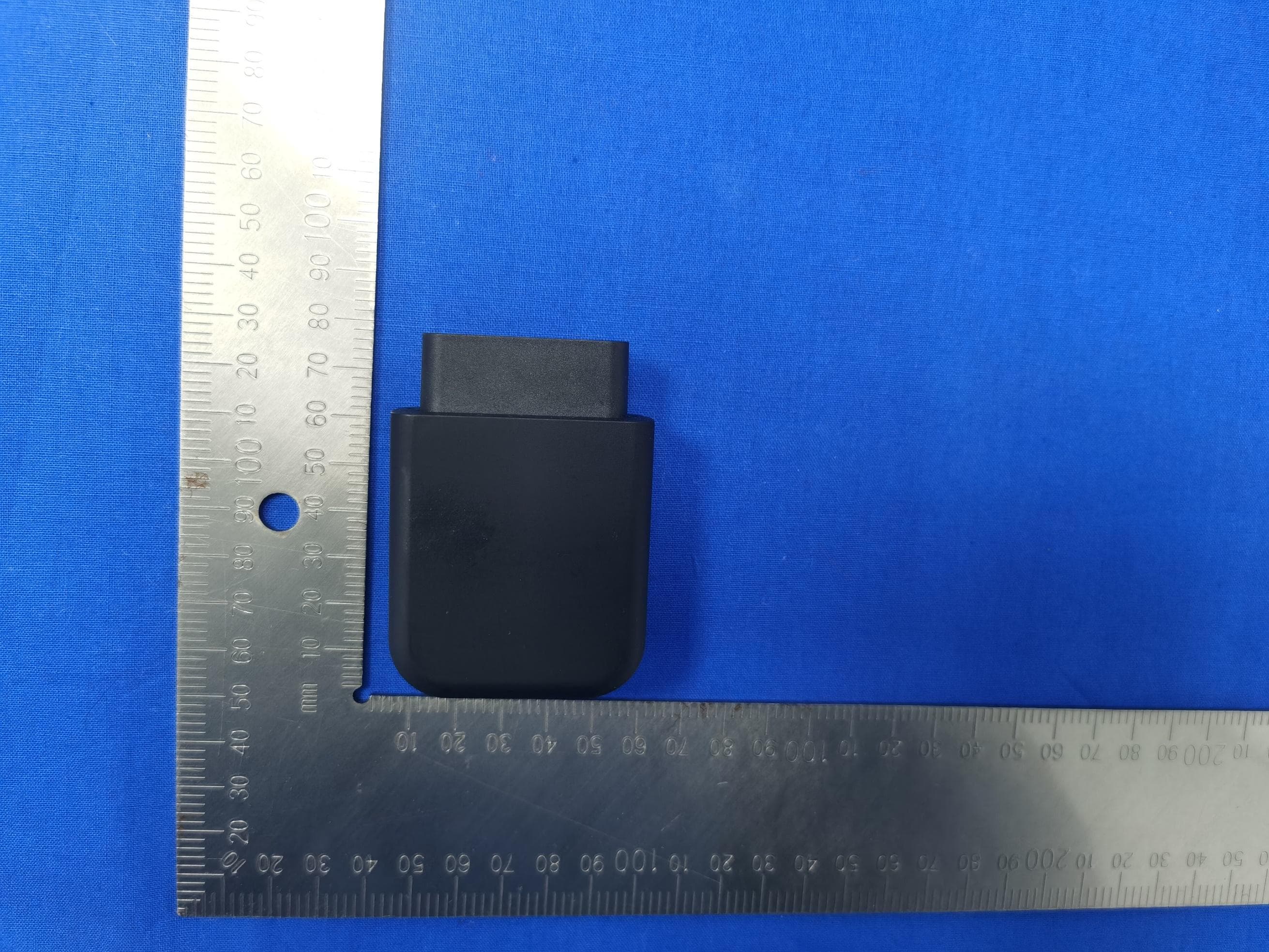
A6GC4D-4G4USV8-4
Jan 08, 2023telematics embedded system
Equipment Class
PCB - PCS Licensed Transmitter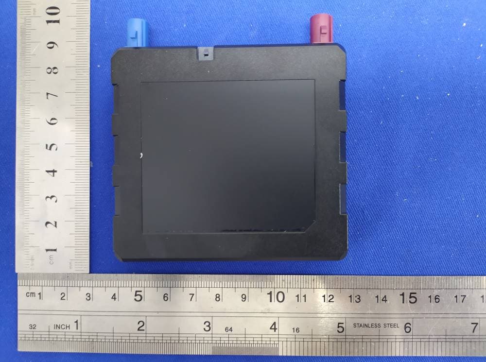
A6GC4MAX-4MUSAAV8
Dec 22, 2022telematics embedded system
Equipment Class
JBP - Part 15 Class B Computing Device Peripheral
A6GC4FLX-4MUSAAV8
Dec 22, 2022telematics embedded system
Equipment Class
CXX - Communications Rcvr for use w/ licensed Tx and CBs
A6GC4D-4G4USV8-2
Jun 05, 2022telematics embedded system
Equipment Class
CXX - Communications Rcvr for use w/ licensed Tx and CBs