A794010
UTC Fire & Security B.V.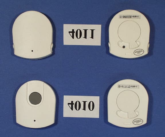
Click to zoom
Application Details
- Equipment Class
- DSC - Part 15 Security/Remote Control Transmitter
- Date of Grant
- Jun 14, 1999
- Application Purpose
- Original Equipment
- Date of Application
- May 09, 1999
- Frequency Range
- 418.00000000 - 418.00000000
- Company
- UTC Fire & Security B.V.
- Country
- Netherlands
Documents & Files
Document Text
Text extracted from the exhibit documents filed with the FCC. Open a document above to read the original.
Users Manual
Intertek Testing Services FCC ID: A794010EXHIBIT 51 EXHIBIT 5 User Manual Sentrol Incorporated FCC Part 15 Application For Certification (Low Power Transmitter) Single and Dual Button Pendant Transmitter Model: 4010 and 4011 FCC ID: A794010 Intertek Testing Services FCC ID: A794010EXHIBIT 52 User Manual Attached is a preliminary copy of the Instruction Manual. The following information will be included in the next revision of the manual: This device complies with Part 15 of the FCC Rules. Operation is subject to the following two conditions: (1) this device may not cause harmful interference, and (2) this device must accept any interference received, including interference that may cause undesired operation. Changes or modifications not expressly approved by Sentrol, Inc. could void the user's authority to operate the equipment. This manual will be provided to the end-user with each unit sold/leased in the United States. GENERAL INFORMATION The Sentrol Model 4010 Single Button Pendant Transmitter is to be used with Sentrol’s 4000 Wireless System having a receiver with Revision J or later software. It is designed as a portable, unsupervised transmitter. It is intended to function in applications where the user will be within the Installer Verified operating range of the overall system. The 4010 is provided with a replaceable 3-volt CR2032 Lithium battery, a necklace and an optional belt clip. The Model 4010 Pendant Transmitter contains one button that must be pressed and held for a minimum of 1.5 seconds to activate. Once the transmitter is activated, it will transmit twice (2 sets of 8 Alarm messages). The red LED will blink once as the first transmission occurs and then ten seconds later as the second transmission occurs. Depending upon the “ ‘C’ Key Function Options” selected during the programming of the compatible Controls and RF Gateway Receiver, the 4010 Pendant Transmitter can Wireless sentrol Model 4010-Single Button Pendant Transmitter activate a Panic/Holdup alarm, or perform similar emer- gency signaling functions by utilizing the “Access” output. The Model 4010 is a single address device and is pro- grammed as a USER and not as a POINT (zone). There- fore, you do not lose one or more points (zones) when using the Model 4010 with your system. You can also restrict the “Authority Level” and “Operation Area” of this USER code, which is described in the Control’s Program- ming Instructions. INSTALLATION Read this section completely before installing! These instructions will provide information on installation requirements and will address some installation situations to be avoided for best performance. Battery Installation To install the battery provided, remove the battery door on the back of the unit by rotating the door counter-clockwise. Place the battery into the unit with the (+) positive marking of the battery facing up in the Battery Compartment. Replace the Battery Door and rotate clock-wise to close and secure the battery. With the battery installed, press and hold the button for two seconds. The LED above the button should blink once and then again in approximately ten seconds. The 4010 Pendant Transmitter is now ready to be programmed into the system. ITEMS YOU WILL NEED •Series 4000 Receiver with software code Revision J or later. •Control Panel Programming Instructions. Sentrol Model 4010Belt Clip LED Latch Tab Slot Necklace Mounting Holes Battery Compartment Door ID Address Label Single Button 6-123456-dddd-r Release Tab Mounting Holes PROGRAMMING The 4010 Pendant Transmitter is pre-programmed with a 6- digit ID address. This ID address is located on the back label and on a label on the box (example of code label- 6- 123456-dddd-r). This 6-digit ID address (underlined) will be needed to program this device into the RF Gateway Receiver and into the Control. During the programming steps, you will be assigning the pendant to a Gateway Receiver “Device Number” and a “Key Function Option Number” from the “C” Key column in the table located in the Control’s Programming Instructions. In addition, you will be programming the last four digits of the Transmitter ID address as a USER code into the Control. You will need to consult the Programming Instructions of the Control for specific instructions on programming. MOUNTING The 4010 Pendant Transmitter has three mounting options provided. Necklace - Use the necklace provided (other necklace styles can be used in place of the one provided) and slip the necklace through the channel on the top edge of the unit. Belt Clip - It can be worn on the belt using the clip provided. Slide the pendant into the clip until it latches. Slide the clip onto the belt. Fixed Mounting - It can mounted in a fixed location using the clip’s mounting holes and screws provided. Once the clip is mounted, slide the pendant into the clip until it latches. TESTING The Pendant Transmitter is an RF device and there may be “blind” or “non operational” locations found during your tests. Normally these can be overcome if the transmitter is moved a short distance left or right. It should not matter how the Pendant Transmitter is positioned or mounted. It is an omni-directional RF transmitter and should therefore transmit in all directions. If the transmitter is portable, this testing needs to be performed from multiple locations to ensure proper operation and that control response exists. For example, if the Pendant is to be used as a “Panic” device from bedside, it should be tested from that location. If it is to be used as a “Panic” device while the user is in the basement, garden or garage, then it should be tested for operation from those areas. Once testing is complete, clearly identify to the users any range or transmission limits found during testing. Review with the User the function of the Pendant Transmitter. Show the user the ID Address Label on the back of the unit. Explain that this ID Label is also a User Pass Code (last four digits of address) wh…
Text truncated - open the document above for the full version.
Block Diagram
Intertek Testing Services FCC ID: A794010EXHIBIT 41 EXHIBIT 4 Block Diagram Sentrol Incorporated FCC Part 15 Application For Certification (Low Power Transmitter) Single and Dual Button Pendant Transmitter Models: 4010 and 4011 FCC ID: A794010
External Photos
Intertek Testing Services FCC ID: A794010EXHIBIT 71 EXHIBIT 7 External Photographs Sentrol Incorporated FCC Part 15 Application For Certification (Low Power Transmitter) Single and Dual Button Pendant Transmitter Models: 4010 and 4011 FCC ID: A794010 Intertek Testing Services FCC ID: A794010EXHIBIT 72 External Photographs (4010 – 4011)
ID Label/Location Info
Intertek Testing Services FCC ID: A794010EXHIBIT 31 EXHIBIT 3 ID Label & Location Sentrol Incorporated FCC Part 15 Application For Certification (Low Power Transmitter) Single and Dual Button Pendant Transmitter Models: 4010 and 4011 FCC ID: A794010 Intertek Testing Services FCC ID: A794010EXHIBIT 32 Label Artwork An engineering drawing of the label will be permanently affixed to the unit is shown below. Please note that due to the size of the device, the model number and trade name will be placed on a separate label. FCC ID: A794010 FCC ID Number
Internal Photos
Intertek Testing Services FCC ID: A794010EXHIBIT 81 EXHIBIT 8 Internal Photographs Sentrol Incorporated FCC Part 15 Application For Certification (Low Power Transmitter) Single and Dual Button Pendant Transmitter Models: 4010 and 4011 FCC ID: A794010 Intertek Testing Services FCC ID: A794010EXHIBIT 82 Internal Photographs PC Board Top View Intertek Testing Services FCC ID: A794010EXHIBIT 83 Internal Photographs PC Board Bottom View
Operational Description
Intertek Testing Services FCC ID: A794010EXHIBIT 11 EXHIBIT 1 Operational Description / Letter of Agency Sentrol Incorporated FCC Part 15 Application For Certification (Low Power Transmitter) Single and Dual Button Pendant Transmitters Models: 4010 and 4011 FCC ID: A794010 Intertek Testing Services FCC ID: A794010EXHIBIT 12 The Sentrol Model 4010 Single Button and 4011 Dual Button Pendant Transmitters are designed to be used with Sentrol 4000 Wireless System having a receiver with Revision J or later software. They are designed as a portable, unsupervised transmitter. They are intended to function in applications where the user will be within the installer verified operating range of the overall system. The 4010 is provided with a replaceable 3 volt CR2032 Lithium battery, necklace and an operational belt clip. The model 4010 Pendant Transmitter contains one button that must be pressed and held for a minimum of 1.5 seconds to activate. Once the transmitter is activated, it will transmit twice (2 sets of 8 Alarm messages). The red LED will blink once as the first transmission occurs and then ten seconds later as the second transmission occurs. The 4011 is provided with a replaceable 3 volt CR2032 Lithium battery, necklace and an operational belt clip. The model 4011 Pendant Transmitter contains two buttons that must be held simultaneously to activate. Once activated, the pendant continuously repeats the alarm (4 alarms messages every 4 seconds) until it is reset by depressing the RESET plunger switch on the back of the unit. Both the 4010 and 4011are intended to be used as a Panic/Holdup alarm, or other similar emergency signaling functions.
Schematics
Intertek Testing Services FCC ID: A794010EXHIBIT 91 EXHIBIT 9 Schematics Sentrol Incorporated FCC Part 15 Application For Certification (Low Power Transmitter) Single and Dual Button Pendant Transmitter Models: 4010 and 4011 FCC ID: A794010
Test Setup Photos
Intertek Testing Services FCC ID: A794010EXHIBIT 61 EXHIBIT 6 Test Setup Photographs Sentrol Incorporated FCC Part 15 Application For Certification (Low Power Transmitter) Single and Dual Button Pendant Transmitter Models: 4010 and 4011 FCC ID: A794010 Intertek Testing Services FCC ID: A794010EXHIBIT 62 Radiated Emission Configuration Photograph X View Intertek Testing Services FCC ID: A794010EXHIBIT 63 Radiated Emission Configuration Photograph Y View Intertek Testing Services FCC ID: A794010EXHIBIT 64 Radiated Emission Configuration Photograph Z View
Contact Information
Applicant
Roger Palmen(Regulatory Lead Engineer)
Technical Contact
Intertek Testing ServiceGreg A Thompson
[email protected]770-925-2444
4317-A PArk Drive NW · Norcross, Georgia · United States
Test Firm
Intertek Testing ServicesDavid Dennis
770-925-2444Fax: 770-925-7294
Technical Specifications
| # | Rule Parts | Frequency Range | Power Output |
|---|---|---|---|
| 1 | 15C | 418 MHz - 418 MHz | - |
Other Applications from UTC Fire & Security B.V.
A794004
Nov 17, 1998DSC - Part 15 Security/Remote Control Transmitter
Equipment Class
DSC - Part 15 Security/Remote Control Transmitter
A79BHS-FOB
Nov 03, 1998Alarm Transmitter
Equipment Class
DSC - Part 15 Security/Remote Control Transmitter
A79BHS-FOB-RCVR
Nov 03, 1998CYY - Communications Receiver used w/Pt 15 Transmitter
Equipment Class
CYY - Communications Receiver used w/Pt 15 TransmitterA794545
Oct 19, 1997Glass Break Alarm Transmitter
Equipment Class
DSC - Part 15 Security/Remote Control TransmitterA794655
Oct 16, 1997DSC - Part 15 Security/Remote Control Transmitter
Equipment Class
DSC - Part 15 Security/Remote Control Transmitter