A7E-UTILIWISEECMunder-the-cover IP-based wireless communications device
Metrum Technologies, LLC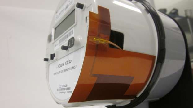
Click to zoom
Application Details
- Equipment Class
- PCB - PCS Licensed Transmitter
- Date of Grant
- Mar 07, 2012
- Application Purpose
- Original Equipment
- Date of Application
- Mar 07, 2012
- Equipment Note
- under-the-cover IP-based wireless communications device
- Frequency Range
- 1850.20000000 - 1909.80000000
- Company
- Metrum Technologies, LLC
- Country
- United States
Documents & Files
Document Text
Text extracted from the exhibit documents filed with the FCC. Open a document above to read the original.
Users Manual
Web: www.metrum.us Office: 254-752-7300 Confidential The contents of this manual are confidential and constitute the exclusive property of METRUM TECHNOLOGIES, LLC. This manual and its contents may not be made public in any manner, distributed or loaned to others or reproduced or copied either in whole or part without prior written consent from Metrum. © 2011 METRUM METRUM UTILIWISE® ENDPOINT COMMUNICATION MODULE USER’S MANUAL i Notice © 2011 Metrum Technologies, LLC All rights reserved. No part of this document may be reproduced or transmitted in any form or by any means, electronic or mechanical, for any purpose without the express written permission of Metrum Technologies, LLC. Metrum Technologies, LLC makes no representations or warranties with respect to the contents or use of this manual and specifically disclaims any warranties, express or implied, of merchantability or fitness for any specific purpose. Further, Metrum Technologies, LLC reserves the right to revise this publication and to make any modifications to its content, at any time, without obligation to notify any party, person, or entity of such revisions or changes. Product specifications cited are those in effect at time of publication. Metrum Technologies, LLC shall not be liable for errors contained herein or for incidental or consequential damages in connection with the furnishing, performance, or use of this material. UtiliWise®, Configurator and ECM are trademarks and/or registered trademarks of Metrum Technologies, LLC. MOTOROLA and the Stylized M Logo are registered in the US Patent & Trademark Office. All other product and company names mentioned herein may be the trademarks and/or registered trademarks of their respective owners. For further information, contact: Metrum Technologies 315 S. University Parks Dr. Waco, TX 76701 Office: 254-752-7300 Fax: 254-752-7302 Email: [email protected] Web: www.metrum.us ii Document History Title: Metrum UtiliWise® Endpoint Communication Module User’s Manual Revision Level Date Issued Description Original 07/2011 Initial Release Version 2.0 12/7/2011 Major update Version 3.0 12/21/2011 Modified FCC Compliance Section iii CONTENTS 1. Metrum UtiliWise® Endpoint Overview ............................................... 1 2. Utiliwise® Endpoint Configuration and Communication ....................... 4 2.1. Utiliwise® Endpoint Configuration Procedure ................................................................................................................................ 4 2.1.1. Connect USB cable to the Utiliwise® Endpoint ................................................................................................................................ 4 2.1.2. Install Metrum Configurator Software ................................................................................................................................................. 6 2.1.3. Use the Metrum Configurator to verify Endpoint Settings .......................................................................................................... 7 2.1.4. ECM Configuration Features for the Verizon Network .............................................................................................................. 10 2.2. IP Communication Procedure for Metrum Wireless ECM’s ..................................................................................................... 11 2.2.1. Cisco AnyConnect ........................................................................................................................................................................................ 11 2.2.2. Site-to-site VPN tunnel.............................................................................................................................................................................. 12 2.3. Initial Inspection, Power-Up, and Troubleshooting Procedures ............................................................................................ 14 Appendix 1 Metrum Utiliwise ® External Endpoint Communication Module 16 1. External ECM Interfaces ................................................................................................................................................................................ 16 2. External ECM LED Indicators ...................................................................................................................................................................... 17 iv FCC Compliance This equipment has been tested and found to comply with the limits for a Class B digital device, pursuant to part 15 of the FCC Rules. These limits are designed to provide reasonable protection against harmful interference in a residential installation. This equipment generates, uses, and can radiate radio frequency energy and, if not installed and used in accordance with the instructions, may cause harmful interference to radio communications. However, there is no guarantee that interference will not occur in a particular installation. If this equipment does cause harmful interference consult Metrum Support for help. v Safety Information The following safety precautions must be observed during all phases of operation, service, and repair of this device. Failure to comply with these precautions or with specific warnings elsewhere in this manual violates safety standards of design, manufacture, and the intended use of the metering instrument. Metrum Technologies, LLC assumes no liability for the customer's failure to comply with these requirements. • Warning: Any work on, or near, energized meters, meter sockets, or other metering equipment can present a danger of electrical shock. All work on this product should be performed only by qualified electricians and metering specialists in accordance with local utility safety practices, utility requirements and procedures outlined in Chapter 14 of The Handbook for Electricity Metering (10th edition). The information contained within this manua…
Text truncated - open the document above for the full version.
Internal Photos
APPLICANT: MOTOROLA INC. FCC ID: IHDP56JE1 Front View (Shields Removed) Rear View (Shields Removed) 1 EXHIBIT 9 APPLICANT: MOTOROLA INC. FCC ID: IHDP56JE1 Front View (With Shield) Rear View (With Shield) 2 EXHIBIT 9
RF Exposure Info
§ 15.247(i) Maximum Permissible Exposure RF Exposure Requirements: §1.1307(b)(1) and §1.1307(b)(2): Systems operating under the provisions of this section shall be operated in a manner that ensures that the public is not exposed to radio frequency energy levels in excess of the Commission’s guidelines. RF Radiation Exposure Limit: §1.1310: As specified in this section, the Maximum Permissible Exposure (MPE) Limit shall be used to evaluate the environmental impact of human exposure to radiofrequency (RF) radiation as specified in Sec. 1.1307(b), except in the case of portable devices which shall be evaluated according to the provisions of Sec. 2.1093 of this chapter. MPE Limit Calculation: EUT’s operating frequencies @ 2400-2483.5 MHz; highest conducted power = 22.38 dBm (peak) therefore, Limit for Uncontrolled exposure: 1 mW/cm 2 or 10 W/m 2 EUT maximum antenna gain = 5 dBi. MPE Limit Calculation: EUT’s operating frequencies @ 1850-1910 MHz; maximum sourced based time-averaged transmit power is 0.125 Watts, Limit for Uncontrolled exposure: 1 mW/cm 2 or 10 W/m 2 EUT maximum antenna gain = 6 dBi. Equation from page 18 of OET 65, Edition 97-01 S = PG / 4R 2 or R = √PG / 4S where, R = Distance (20cm) P = Power Input to antenna (mW) G = Antenna Gain ( numeric) 2.4 GHz Band 1900 MHz S = PG/4πR² S = PG/4πR² (173mW)(3.16) (125mW)(3.98) 4π(20)² 4π(20)² S1 = 0.1088 mW/cm 2 S2 = 0.099mW/cm 2 S Power density (mW/cm²) General Population Limit (mW/cm²) S as a fraction of the limit (%) S1 0.1088 1 10.9 S2 0.099 1 9.9 The total density is 0.1088+0.099 = 0.2078 mW/cm2. The total density does not exceed 1 per OET 65 requirements when the spectral power density is calculated at least 20cm away from the unit. MPE Limit Calculation: EUT’s operating frequencies @ 2400-2483.5 MHz; highest conducted power = 22.38 dBm (peak) therefore, Limit for Uncontrolled exposure: 1 mW/cm 2 or 10 W/m 2 EUT maximum antenna gain = 5 dBi. MPE Limit Calculation: EUT’s operating frequencies @ 824-849 MHz; maximum sourced based time-averaged transmit power is 0.25 Watts, Limit for Uncontrolled exposure: 0.549 mW/cm 2 or 10 W/m 2 EUT maximum antenna gain = 6 dBi. Equation from page 18 of OET 65, Edition 97-01 S = PG / 4R 2 or R = √PG / 4S where, R = Distance (20cm) P = Power Input to antenna (mW) G = Antenna Gain ( numeric) 2.4 GHz Band 824 MHz S = PG/4πR² S = PG/4πR² (173mW)(3.16) (250mW)(3.98) 4π(20)² 4π(20)² S1 = 0.1088 mW/cm 2 S2 = 0.198mW/cm 2 S Power density (mW/cm²) General Population Limit (mW/cm²) S as a fraction of the limit (%) S1 0.1088 1 10.9 S1 0.198 0.549 36.1 The total density is 0.1088+0.198 = 0.3068 mW/cm2. The total density does not exceed 0.549 per OET 65 requirements when the spectral power density is calculated at least 20cm away from the unit.
Test Report
APPLICANT: MOTOROLA INC FCC ID: IHDT56DB2 PERSONAL COMMUNICATIONS SECTOR PRODUCT SAFETY AND COMPLIANCE EMC LABORATORY EMC TEST REPORT Test Report Number – 14081-1 Report Date – June 23, 2005 The test results contained herein relate only to the model(s) identified. It is the manufacturer’s responsibility to assure that additional production units of this model are manufactured with identical electrical and mechanical characteristics. As the responsible EMC Engineer, I hereby declare that the equipment tested as specified in this report conforms to the requirements indicated . Signature Name: Michael E. Hill NARTE: EMC002258-NE Title: Senior Staff Electrical Engineer Date: June 23, 2005 This report must not be reproduced, except in full, without written approval from this laboratory. THIS REPORT MUST NOT BE USED TO CLAIM PRODUCT ENDORSEMENT BY A2LA OR ANY AGENCY OF THE U.S. GOVERNMENT. A2LA Certificate Number: 1846-01 EXHIBIT 6 APPLICANT: MOTOROLA INC FCC ID: IHDT56DB2 Table of Contents Description Page Test Report Details 3 Applicable Standards 3 Summary of Testing 4 General and Special Conditions 4 Equipment and Cable Configurations 5 Measuring Equipment and Calibration Information 5 Measurement Procedures and Data RF Power Output 6 Occupied Bandwidth 7 GSM 850 Reference Plot 8 GSM 850 Occupied Bandwidth Plot 8 GSM 850 Lower Band Edge 9 GSM 850 Upper Band Edge 9 GSM 1900 Reference Plot 10 GSM 1900 Occupied Bandwidth Plot 10 GSM 1900 Lower Band Edge 11 GSM 1900 Upper Band Edge 11 Spurious Emissions at Antenna Terminals 12 GSM 850 Tabular and Graphical Data 13 GSM 1900 Tabular and Graphical Data 14 Field Strength of Spurious Emissions 15 GSM 850 Tabular and Graphical Data 16 GSM 1900 Tabular and Graphical Data 17 Frequency Stability 19 GSM 850 Tabular and Graphical Data 20 GSM 1900 Tabular and Graphical Data 21 Field Strength of Spurious Emissions from Unintentional Radiators 22 GSM 850 Graphical Data 23 GSM 1900 Tabular and Graphical Data 24 Appendix A - Radiated Emissions Test Setup Photos Figure A.1 – Radiated Emissions Measurement 25 Figure A.2 – Substitution Measurement 25 Test Report Number: 14081-1 EXHIBIT 6 2 APPLICANT: MOTOROLA INC FCC ID: IHDT56DB2 Test Report Details Tests Performed By: Motorola Mobile Devices Business Product Safety and Compliance Group 600 North US Hwy 45 Libertyville, IL 60048 PH (847) 523-6167 Fax (847) 523-4538 Motorola MDB FRN: 0004321311 FCC Registration Number: 316588 Industry Canada Number: IC3908 Tests Requested By: Motorola Inc. Mobile Devices Business 600 North US Hwy 45 Libertyville, IL 60048 Product Type: Cellular Phone Signaling Capability: GSM 850, 1900 Bluetooth Model Number: G20 Version: F2838 Serial Numbers: 010186000055256, 010186000055249 Testing Complete Date: July 9, 2004 Applicable Standards All tests and measurements indicated in this document were performed in accordance with the Code of Federal Regulations Title 47 Part 2, Sub-part J as well as the following parts: X Part 15 Subpart B – Unintentional Radiators X Part 22 Subpart H - Public Mobile Services X Part 24 - Personal Communications Services Part 90 - Private Land Mobile Radio Service Applicable Standards: TIA EIA 137-A, TIA EIA 98-C, ANSI 63.4 2001, RSS-118 (AMPS), RSS-128 (TDMA), RSS-129 (CDMA), RSS-133 (CELLULAR) Test Report Number: 14081-1 EXHIBIT 6 3 APPLICANT: MOTOROLA INC FCC ID: IHDT56DB2 Summary of Testing Test Test Name # Pass/Fail 1 RF Power Output NA 2 ERP (Effective Radiated Power) NA 3 Modulation Characteristics Pass 4 Occupied Bandwidth Pass 5 Spurious Emissions at Antenna Terminal Pass 6 Field Strength of Spurious Emissions Pass 7 Frequency Stability Pass 8 Field Strength of Spurious Emissions Pass from Unintentional Radiators Test Test Name Margin with respect # to the Limit_________ 1 RF Power Output NA 2 ERP (Effective Radiated Power) NA 3 Modulation Characteristics NA 4 Occupied Bandwidth See Plots 5 Spurious Emissions at Antenna Terminal 19.0 dB 6 Field Strength of Spurious Emissions 4.3 dB 7 Frequency Stability 166.00 Hz 8 Field Strength of Spurious Emissions Below noise floor from Unintentional Radiators The margin with respect to the limit is the minimum margin for all modes and bands. ( ) indicates the margin at which the product exceeds the limit. General and Special Conditions The EUT was tested using a fully charged battery when applicable. Where a battery could not be used due to the need for a controlled variation of input voltage, an external power supply was utilized. All testing was done in an indoor controlled environment with an average temperature of 22º C and relative humidity of 50%. Test Report Number: 14081-1 EXHIBIT 6 4 APPLICANT: MOTOROLA INC FCC ID: IHDT56DB2 Equipment and Cable Configurations The EUT was tested in a stand-alone configuration that is representative of typical use. Measuring Equipment and Calibration Information ManufacturerEquipment TypeModel No.Serial Number Cal. Due Date Rohde & SchwarzReceiverESI26838786/0105/17/2005 Hewlett-PackardEMC Analyzer8593EM3536A0011810/2/2004 Hewlett-PackardEMC Analyzer7405US3944019111/13/2004 MiteqPreamplifier 0.1-26.5GHzNSP2650-NF-S9663501/8/2005 ETSDRG Horn Antenna31156222 9/29/2004 A.H. Systems Inc.DRG Horn AntennaSAS-2--/57136512/17/2004 ETSLog-Periodic Antenna314811883/5/2005 ETSBiconical Antenna3110B337011/14/2004 AttenuatorWeinschelAS-6667510/14/2004 AttenuatorWeinschelAS-6667711/4/2004 Rohde & SchwarzMobile Test SetCMD 80DE29008N/A Hewlett-PackardSignal Generator83623B3844A011956/20/2005 ThermotronEnvironmental ChamberS-4315801/5/2005 Hewlett-PackardPre-Amplifier8347A3307A0200111/4/2004 AgilentPower MeterEE4418BGB4020638812/5/2004 AgilentPower SensorE4412BUS3848632111/23/2004 Hewlett-PackardPre-Amplifier8447F2805A034195/19/2005 All equipment is on a one-year calibration cycle. Test Report Number: 14081-1 EXHIBIT 6 5 APPLICANT: MOTOROLA INC FCC ID: IHDT56DB2 Measurement Procedures and Data RF POWER OUTPUT Measurement Procedure The RF output port of the equipment under test is direct…
Text truncated - open the document above for the full version.
Test Setup Photos
Photograph 1. Conducted Emissions, Test Setup, Front View Photograph 2. Conducted Emissions, Test Setup, Rear View Photograph 3. Radiated Emissions, Test Setup, 30 MHz – 1 GHz Photograph 4. Radiated Emissions, Test Setup, Rear View Photograph 5. Radiated Emissions, Test Setup, Front View Photograph 6. Radiated Spurious Emissions, Test Setup
Contact Information
Applicant
Dennis McCain(VP of Operations)
Technical Contact
Metrum Technologies, LLCDennis McCain
[email protected]254-752-7300
315 South University Parks Drive · Waco, Texas · United States
Non-Technical Contact
Metrum Technologies, LLCDavid Simmons
[email protected]254-752-7300
Test Firm
MET Laboratories Inc.Robert Frier
Technical Specifications
| # | Rule Parts | Frequency Range | Power Output | Emission | Tolerance |
|---|---|---|---|---|---|
| 2 | 24E | 1.85 GHz - 1.91 GHz | 900.00 mW | 242KGXW | 0.1 ppm |