A7HYOS-3807Short Range Radar
YOKOWO CO.,LTD.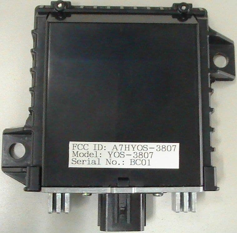
Click to zoom
Application Details
- Equipment Class
- FDS - Part 15 Field Disturbance Sensor
- Date of Grant
- Feb 14, 2012
- Application Purpose
- Original Equipment
- Date of Application
- Feb 14, 2012
- Equipment Note
- Short Range Radar
- Frequency Range
- 24085.00000000 - 24165.00000000
- Company
- YOKOWO CO.,LTD.
- Country
- Japan
Documents & Files
Document Text
Text extracted from the exhibit documents filed with the FCC. Open a document above to read the original.
Users Manual
YOS-3807 Short Range Radar Operating Manual [ HEAD OFICE ] 7-5-11 Takinogawa, Kita-ku, Tokyo 114-8515 Japan TEL: +81(0)3 3916 3173 FAX: +81(0)3 3916 8316 [ TOMIOKA PLANT ] 1112 Kanohara Tomioka-Shi, Gunma 370-2495 Japan TEL: +81(0)274 62 2121 FAX: +81(0)274 62 2110 YOKOWO CO., LTD. R&D division Permission Checked by Issued by No. M122111-001 Page 1 / 7 Table of Contents 1. Information to end-user 1.1 Information 1.2 Caution 2. Ambient conditions 2.1 Temperature range 3. Function overview 3.1 BSI (Blind Spot Information) 3.2 CTA (Cross Traffic Alert) 4. Installation to a vehicle 4.1 Installation position No. M122111-001 Page 2 / 7 1. Information to the end-user In accordance with FCC regulation, following information and caution shall be placed in a prominent location in the instruction manual or pamphlet supplied to the end-user. 1.1 Information This device complies with part 15 of the FCC Rules. Operation is subject to the following two conditions: (1) This device may not cause harmful interference, and (2) this device must accept any interference received, including interference that may cause undesired operation. 1.2 Caution Changes or modifications not expressly approved by the party responsible for compliance could void the user’s authority to operate the equipment. No. M122111-001 Page 3 / 7 2. Ambient conditions 2.1 Temperature ranges Storage temperature range: -40 to +95°C Operating temperature range: -30 to +85°C No. M122111-001 Page 4 / 7 3. Function overview 3.1 BSI (Blind Spot Information) 5m 2m 3.8m 0.5m Sensor is origin of distance BSI alert area is symmetric. 5m 2m 3.8m 0.5m Sensor is origin of distance BSI alert area is symmetric. Fig.3-1 BSI alert area ( based on ISO 17387 :2008 ) Blind Spot Information system (BSI) assist driver to changing lane. If vehicle is in blind spot area, radar detected the vehicle and alert the existence to driver by illuminating indicator lamp and buzzer. Fig.3-1 shows BSI alert area. BSI works when BSI system is turned on and vehicle speed exceeds 10km/h. No. M122111-001 Page 5 / 7 3.2 CTA (Cross Traffic Alert) Fig.3-2 Cross Traffic Alert area The Cross Traffic Alert system assists drivers in backing up by warning drivers of impending traffic while reversing. Fig.3-2 shows Cross Traffic Alert area. CTA works when a gear is put into the back. Symbol values X: max. 10m θ : 30° Parking vehicles A moving vehicle A vehicle with the sensor Alert area θ x No. M122111-001 Page 6 / 7 4. Installation to a vehicle 4.1 Installation position Fig.4-1 The image of sensor positions Fig.4-2 The sensor shape No. M122111-001 Page 7 / 7 93.7mm 77mm typ. height 0.5m Fig.4- 1 shows the sensor position. Sensors are installed on each side of the rear. Position of sensors is inside of a bumper, is at a height of around 0.5 meter. Fig.4-2 shows the shape of sensor. It is only a vehicle maker that installs the sensor.
External Photos
Short Range Radar External Photo Fig.1 front Fig.2 top Page 1 / 3 Short Range Radar External Photo Fig.3 back Fig.4 bottom Page 2 / 3 Short Range Radar External Photo Fig.3 right Fig.6 left Page 3 / 3
ID Label/Location Info
Short Range Radar Label Photo Fig.1 Label Location Fig.2 Label Design Page 1 / 1
Internal Photos
Short Range Radar Internal Photo Fig.1 RF PCB1 Fig.2 RF PCB2 Page 1 / 5 Short Range Radar Internal Photo Fig.3 RF Cover Fig.4 BaseBand PCB1 Page 2/ 5 Short Range Radar Internal Photo Fig.5 BaseBand PCB2 Fig.6 BaseBand Covers Page 3 / 5 Short Range Radar Internal Photo Fig.7 Antenna PCB1 Fig.8 Antenna PCB2 Page 4 / 5 Short Range Radar Internal Photo Fig.9 Positions of BaseBand and Antennas Fig.10 Position of RF Page 5 / 5
Test Report
Test report No. : 32EE0108-HO-01-R2 Page : 2 of 16 Issued date : January 24, 2012 Revised date : February 14, 2012 FCC ID : A7HYOS-3807 UL Japan, Inc. Head Office EMC Lab. 4383-326 Asama-cho, Ise-shi, Mie-ken 516-0021 JAPAN Telephone : +81 596 24 8116 Facsimile : +81 596 24 8124 CONTENTS PAGE SECTION 1: Customer information ············································································· 3 SECTION 2: Equipment under test (E.U.T.) ··································································· 3 SECTION 3: Test specification, procedures & results ························································ 4 SECTION 4: Operation of E.U.T. during testing ······························································ 7 SECTION 5: Radiated emission (Fundamental and Spurious Emission) ································· 8 SECTION 6: 20dB Bandwidth and 99% Occupied bandwidth ··········································· 10 APPENDIX 1: Data of EMI test ················································································· 11 Radiated Emission (Electric Field Strength of Fundamental and Spurious Emission) ..................... 11 -20dB and 99% Occupied Bandwidth ............................................................................................... 13 Duty Cycle ........................................................................................................................................ 14 APPENDIX 2: Test Instruments ················································································· 15 APPENDIX 3: Photographs of test setup ······································································ 16 Radiated emission ............................................................................................................................. 16 Test report No. : 32EE0108-HO-01-R2 Page : 3 of 16 Issued date : January 24, 2012 Revised date : February 14, 2012 FCC ID : A7HYOS-3807 UL Japan, Inc. Head Office EMC Lab. 4383-326 Asama-cho, Ise-shi, Mie-ken 516-0021 JAPAN Telephone : +81 596 24 8116 Facsimile : +81 596 24 8124 SECTION 1: Customer information Company Name : YOKOWO CO.,LTD. Address : No.5-11 Takinogawa 7-chome, Kita-ku, Tokyo 114-8515, Japan Telephone Number : +81-3-3916-3111 Facsimile Number : +81-3-3916-3184 Contact Person : Yui Koda SECTION 2: Equipment under test (E.U.T.) 2.1 Identification of E.U.T. Type of Equipment : Short Range Radar Model No. : YOS-3807 Serial No. : Refer to Section 4, Clause 4.2 Rating : DC12V Receipt Date of Sample : December 22, 2011 Country of Mass-production : Japan Condition of EUT : Production prototype (Not for Sale: This sample is equivalent to mass-produced items.) Modification of EUT : No Modification by the test lab 2.2 Product Description Feature of EUT Short Range Radar is mounted on the vehicle. General Specification Clock frequency(ies) in the system : 20MHz Radio Specification Radio Type : Transceiver Frequency of Operation : 24.085GHz - 24.165GHz Modulation : ASK Power Supply (radio part input) : DC5.0V, DC-0.4V Antenna type : PCB Antenna Antenna Gain : 16dBi Test report No. : 32EE0108-HO-01-R2 Page : 4 of 16 Issued date : January 24, 2012 Revised date : February 14, 2012 FCC ID : A7HYOS-3807 UL Japan, Inc. Head Office EMC Lab. 4383-326 Asama-cho, Ise-shi, Mie-ken 516-0021 JAPAN Telephone : +81 596 24 8116 Facsimile : +81 596 24 8124 SECTION 3: Test specification, procedures & results 3.1 Test Specification Test Specification : FCC Part 15 Subpart C: 2012, final revised on February 1, 2012 Title : FCC 47CFR Part15 Radio Frequency Device Subpart C Intentional Radiators Section 15.245 Operation within the bands 902 – 928MHz, 2435 – 2465MHz, 5785 – 5815MHz, 10500 – 10550MHz, and 24075 – 24175MHz. *The revision on February 1, 2012 does not affect the test specification applied to the EUT. 3.2 Procedures and results Item Test Procedure Specification Worst margin Results Remarks Conducted Emission FCC: ANSI C63.4:2003 7. AC powerline Conducted Emission measurements FCC: Section 15.207 N/A *1) N/A N/A IC: RSS-Gen 7.2.4 IC: RSS-Gen 7.2.4 Electric Field Strength of Fundamental Emission FCC: ANSI C63.4:2003 13. Measurement of intentional radiators FCC: Section15.245(b) 26.6dB 24151.550MHz, AV, Hori. Complied Radiated IC: RSS-Gen 4.8 IC: RSS-210 A7.1 RSS-Gen 7.2.3 Electric Field Strength of Spurious Emission FCC: ANSI C63.4:2003 13. Measurement of intentional radiators FCC: Section 15.205 Section 15.209 Section 15.245(b) 2.2dB 24175.000MHz, PK, Hori. Complied Radiated IC: RSS-Gen 4.9 IC: RSS-210 A7.1, A7.2 RSS-Gen 7.2.5 -20dB Bandwidth FCC: ANSI C63.4:2003 13. Measurement of intentional radiators FCC: Section15.215(c) See Data Complied Radiated IC: - IC: Reference data Note: UL Japan, Inc.’s EMI Work Procedures No. 13-EM-W0420 and 13-EM-W0422. *1) The test is not applicable since the EUT is not the device that is designed to be connected to the public utility (AC) power line. * In case any questions arise about test procedure, ANSI C63.4: 2003 is also referred. FCC 15.31 (e) This EUT provides stable voltage (DC5.0V, DC-0.4V) constantly to RF Part regardless of input voltage. Therefore, this EUT complies with the requirement. FCC Part 15.203 Antenna requirement It is impossible for end users to replace the antenna, because the antenna is mounted inside of the EUT. Therefore, the equipment complies with the antenna requirement of Section 15.203. Test report No. : 32EE0108-HO-01-R2 Page : 5 of 16 Issued date : January 24, 2012 Revised date : February 14, 2012 FCC ID : A7HYOS-3807 UL Japan, Inc. Head Office EMC Lab. 4383-326 Asama-cho, Ise-shi, Mie-ken 516-0021 JAPAN Telephone : +81 596 24 8116 Facsimile : +81 596 24 8124 3.3 Addition to standard Item Test Procedure Specification Worst margin Results Remarks 99% Occupied Bandwidth IC: RSS-Gen 4.6.1 IC: RSS-Gen 4.6.1 N/A - Radiated Other than above, no addition, exclusion nor deviation has been made from the standard. 3.4 Uncertainty EMI The following uncertainti…
Text truncated - open the document above for the full version.
Test Setup Photos
Test report No. : 32EE0108-HO-01-R2 Page : 16 of 16 Issued date : January 24, 2012 Revised date : February 14, 2012 FCC ID : A7HYOS-3807 UL Japan, Inc. Head Office EMC Lab. 4383-326 Asama-cho, Ise-shi, Mie-ken 516-0021 JAPAN Telephone : +81 596 24 8116 Facsimile : +81 596 24 8124 APPENDIX 3: Photographs of test setup Radiated emission Photo 1 Photo 2
Contact Information
Applicant
Shoichi Koshikawa(Deputy Chief)
Technical Contact
UL Japan, Inc.Takahiro Hatakeda
[email protected]81-596-24-8116
4383-326 Asama-cho, Ise-shi · Mie-ken · Japan
Test Firm
UL Japan, Inc. Head office EMC Lab.Tetsuya Hashimoto
Technical Specifications
| # | Rule Parts | Frequency Range | Power Output |
|---|---|---|---|
| 1 | 15.245 | 24.09 GHz - 24.16 GHz | - |