A7L01110ESI Ceiling Fan Remote Transmitter
Shanghai Xinpeng Industry Co. Ltd.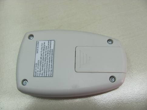
Click to zoom
Application Details
- Equipment Class
- DSC - Part 15 Security/Remote Control Transmitter
- Date of Grant
- Feb 27, 2012
- Application Purpose
- Original Equipment
- Date of Application
- Feb 27, 2012
- Equipment Note
- ESI Ceiling Fan Remote Transmitter
- Frequency Range
- 433.92000000 - 433.92000000
- Country
- China
Documents & Files
Document Text
Text extracted from the exhibit documents filed with the FCC. Open a document above to read the original.
Users Manual
Revision: 01/17/12 ESI Ceiling Fan Remote Transmitter General • Remote is used for controlling a ceiling fan with brushless DC motor • Silicon Labs, SI4010 integrated CMOS SoC RF transmitter • 433.92 MHz operating frequency • PCB printed antenna • 3 Volt CR2032 coil-cell battery powered Button Functions 1. Speed 1 – Commands motor to set speed 1 2. Speed 2 – Commands motor to set speed 2 3. Speed 3 – Commands motor to set speed 3 4. Speed 4 – Commands motor to set speed 4 5. Speed 5 – Commands motor to set speed 5 6. Speed 6 – Commands motor to set speed 6 7. Master Off – Commands motor to STOP and turns the lights OFF 8. Stop – Commands motor to STOP 9. Light – Toggles the light output 10. Reverse – Toggles the motor’s direction of rotation Revision: 01/17/12 FCC Caution: This device complies with Part 15 of the FCC Rules. Operation is subject to the following two conditions: (1) this device may not cause harmful interference, and (2) this device must accept any interference received, including interference that may cause undesired operation. Changes or modifications not expressly approved by the party responsible for compliance could void the user's authority to operate the equipment. This equipment has been tested and found to comply with the limits for a Class B digital device, pursuant to part 15 of the FCC Rules. These limits are designed to provide reasonable protection against harmful interference in a residential installation. This equipment generates uses and can radiate radio frequency energy and, if not installed and used in accordance with the instructions, may cause harmful interference to radio communications. However, there is no guarantee that interference will not occur in a particular installation. If this equipment does cause harmful interference to radio or television reception, which can be determined by turning the equipment off and on, the user is encouraged to try to correct the interference by one or more of the following measures: -Reorient or relocate the receiving antenna. -Increase the separation between the equipment and receiver. -Connect the equipment into an outlet on a circuit different from that to which the receiver is connected. -Consult the dealer or an experienced radio/TV technician for help.
External Photos
FCC ID: A7L01110 Page 1 of 2 External Picture FCC ID: A7L01110 Page 2 of 2
ID Label/Location Info
FCC Label Position
Internal Photos
FCC ID: A7L01110 Page 1 of 3 Internal Picture FCC ID: A7L01110 Page 2 of 3 FCC ID: A7L01110 Page 3 of 3
Test Report
FCC ID: A7L01110 Page 1 of 12 Test Data FCC ID: A7L01110 Page 2 of 12 1. Fundamental & Spurious Emission & Restrict band radiated emission Horizontal 30-1000MHz 10 20 30 40 50 60 70 80 Level [dBμV/m] 30M50M70M100M200M300M500M 700M 1G Frequency [Hz] x x x x x x xMES WAKE0207_H3_red MES WAKE0207_H3_pre LIM FCC 15 F 3 QP Field Strength QP FCC ID: A7L01110 Page 3 of 12 Restrict band 0 10 20 30 40 50 60 70 80 Level [dBμV/m] 399.9M 402M 404M406M408M 410M Frequency [Hz] MES wake0207_HR_pre LIM FCC 15 F 3 QP Field Strength QP FCC ID: A7L01110 Page 4 of 12 1000-4500MHz 0 10 20 30 40 50 60 70 80 Level [dBμV/m] 1G1.5G2G2.5G3G3.5G4G 4.5G Frequency [Hz] x x x x x x xMES WAKE0207_H33_red MES WAKE0207_H33_pre LIM FCC 15 F 3 QP Field Strength QP FCC ID: A7L01110 Page 5 of 12 Vertical 30-1000MHz 10 20 30 40 50 60 70 80 Level [dBμV/m] 30M50M70M100M200M300M500M 700M 1G Frequency [Hz] x x x x x x x MES WAKE0207_V3_red MES WAKE0207_V3_pre LIM FCC 15 F 3 QP Field Strength QP FCC ID: A7L01110 Page 6 of 12 Restrict band 0 10 20 30 40 50 60 70 80 Level [dBμV/m] 399.9M402M404M406M408M 410M Frequency [Hz] LIM FCC 15 F 3 QP Field Strength QP MES wake0207_VR_pre FCC ID: A7L01110 Page 7 of 12 1000-4500MHz 0 10 20 30 40 50 60 70 80 Level [dBμV/m] 1G1.5G2G2.5G3G3.5G4G4.5G Frequency [Hz] x x x x x x x MES WAKE0207_V33_red MES WAKE0207_V33_pre LIM FCC 15 F 3 QP Field Strength QP FCC ID: A7L01110 Page 8 of 12 2. Deactivating time FCC ID: A7L01110 Page 9 of 12 3. Emission bandwidth Emission bandwidth = 433.470MHz – 433.262MHz = 208 kHz FCC ID: A7L01110 Page 10 of 12 4. Occupied bandwidth FCC ID: A7L01110 Page 11 of 12 5. Duty Cycle FCC ID: A7L01110 Page 12 of 12 All the keys were assessed and the test data with maximum duty cycle was listed above. The worst Duty cycle = 10.7 / 48.1 = 22.2%
Test Setup Photos
FCC ID: A7L01110 Page 1 of 7 Test Setup FCC ID: A7L01110 Page 2 of 7 1. Radiated Emission 30MHz-1000MHz, X axis FCC ID: A7L01110 Page 3 of 7 30MHz-1000MHz, Y axis FCC ID: A7L01110 Page 4 of 7 30MHz-1000MHz, Z axis FCC ID: A7L01110 Page 5 of 7 Higher than 1GHz, X axis FCC ID: A7L01110 Page 6 of 7 Higher than 1GHz, Y axis FCC ID: A7L01110 Page 7 of 7 Higher than 1GHz, Z axis
Contact Information
Applicant
Maobing Chu(Project Manager)
Technical Contact
Intertek Testing Services Limited ShanghaiWang Wakeyou
[email protected]86 21 61278448
Shanghai · China
Test Firm
Intertek Testing Services Limited ShanghaiJonny Jing
Technical Specifications
| # | Rule Parts | Frequency Range | Power Output |
|---|---|---|---|
| 1 | 15.231 | 433.92 MHz - 433.92 MHz | - |