A8PJEHBOPF2USB Powered Bridge Interface Tranceiver
HBO/Time Warner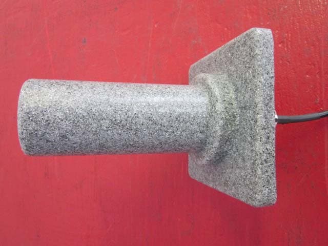
Click to zoom
Application Details
- Equipment Class
- DXT - Part 15 Low Power Transceiver, Rx Verified
- Date of Grant
- Feb 15, 2012
- Application Purpose
- Original Equipment
- Date of Application
- Feb 15, 2012
- Equipment Note
- USB Powered Bridge Interface Tranceiver
- Frequency Range
- 2408.00000000 - 2473.00000000
- Company
- HBO/Time Warner
- Country
- United States
Documents & Files
Document Text
Text extracted from the exhibit documents filed with the FCC. Open a document above to read the original.
Users Manual
!"#$%&'()!*+&,-#"&%).#/# 0#*+1()2)3%"45#+()6 Operation Manual App Version: 1.0.0 Document Version: 1.1 Author: Brian Langel ([email protected]) Last Updated: February 10, 2012 !"#$%&'()!*+&,-#"&%).#/# 0#*+1()2)3%"45#+()6 ©2010 Home Box Office, Inc. Overview 4 Context Diagram 4 PunchForce Operator Tasks 5 Preconditions 5 PunchForce Application 6 Application Startup 6 PunchForce Desktop 7 Status Area 8 Finders (searching for data) 10 Finder Toolbar 10 Editors (adding/editing data) 13 General Editor Information 13 Talent Editor 14 Event Editor 14 Bout Editor 15 Sensor Monitor 16 Sensor Monitor Toolbar 16 Individual Sensor Unit 18 Testing the Sensor Units Pre-Fight 19 Fight Night Dashboard 21 Dashboard Wizard 21 Dashboard Post-Wizard 23 Dashboard Layout 23 Dashboard Toolbar 25 Concise Sensor Monitor 28 Boxer Punch Statistics 30 Graph Slider 31 Graph View 32 Troubleshooting 34 Could Not Login 34 Server is Disconnected 35 Truck Test Connection Failed 35 Sensor Unit Errors 36 Dashboard Wizard Errors 38 Within Dashboard, Truck Connection Issues 38 Page 2 of 49 !"#$%&'()!*+&,-#"&%).#/# 0#*+1()2)3%"45#+()6 Punch Discrepancy Between Boxer and Application 39 FCC PART 15 COMPLIANCE INFORMATION 40 Appendix A: Hardware Parts 41 Sensor Unit 41 Base Unit 42 Base Unit Antenna 43 Sensor Unit Charger 44 Auxiliary Hardware (cables, etc) 45 Appendix B: Hardware Installation/Usage 46 Sensor Unit On/Off 46 Sensor Unit Glove Placement 47 Charging the Sensor Units 48 Setting up the Base Unit 49 Page 3 of 49 !"#$%&'()!*+&,-#"&%).#/# 0#*+1()2)3%"45#+()6 PunchForce System Overview The PunchForce system comprises hardware which records the speed and force of a boxer’s punch during a live boxing match with software which graphs the data and feeds it to systems for viewing. The data is simultaneously stored in a database for use via online applications as well as sent to a broadcast truck to be rendered into graphics for on-air viewing. This document will concentrate on the part of the system known as the PunchForce application. Only enough context required to understand the application is included. Context Diagram Page 4 of 49 !"#$%&'()!*+&,-#"&%).#/# 0#*+1()2)3%"45#+()6 PunchForce Operator Tasks For a live fight, the PunchForce laptop operator is responsible for the following tasks: • Data entry of ‘tale of tape’ information for each boxer. • Determining the sensor units to be used for each boxer. • Assisting and verifying that each sensor unit is properly taped to the correct wrist for each glove of each boxer. • Establishing internet connectivity (whether wired or wireless) for the laptop. • Setting up and verifying that the base unit is attached to the laptop and recognized by the application. • Verifying the PunchForce application can connect to the server (i.e., the database). • Verifying the PunchForce application can connect to the broadcast truck (known as The Hancock). • Setup the PunchForce dashboard for the fight (i.e., select Event, Bout, map sensors to boxers). Preconditions Before each fight, the ‘tale of tape’ information must be obtained from HBO Sports for each boxer of each bout within the event. This information needs to be entered into the PunchForce application (see above). This data entry can be done prior to fight night. Page 5 of 49 !"#$%&'()!*+&,-#"&%).#/# 0#*+1()2)3%"45#+()6 PunchForce Application Application Startup After connectivity has been ensured (by opening a web browser and successfully viewing a page on the internet), the application may be launched by double-clicking the PunchForce icon on the desktop: Upon application launch, the Splash Screen will appear: Shortly, the PunchForce application will prompt for login, enter the username and password (these will be provided and will rarely change, if they do change, PunchForce operators will be notified). Page 6 of 49 !"#$%&'()!*+&,-#"&%).#/# 0#*+1()2)3%"45#+()6 For error conditions at this step, see Troubleshooting below. Upon successful login, the PunchForce application will load and the PunchForce desktop screen will show. PunchForce Desktop The PunchForce desktop is comprised of the top navigation bar along with the desktop area where PunchForce windows are displayed. The navigation bar consists of the following items. • Finders (search for existing data) • Data Entry (add new, edit existing Boxer/Event) • Sensor Monitor (check which sensor units are in range, check health of in-range sensors) Page 7 of 49 !"#$%&'()!*+&,-#"&%).#/# 0#*+1()2)3%"45#+()6 • Fight Night Dashboard (opens the fight night dashboard where punches are recorded) • Status Area (gives detailed information about configuration as well as server/truck connections) Status Area This area is located in the upper right corner of the PunchForce desktop. It includes the Server Status, the Reconnect to Server, the Test Truck Connection, the Configuration Information and the Toggle Application Menu buttons. Server Status This should always be green and display Connected to Server. If not please see Troubleshooting below. Reconnect to Server If already connected, clicking this button simply opens a dialog displaying the server status. If the application becomes disconnected, clicking this button brings up a dialog allowing the operator to reconnect to the server, see Troubleshooting below. Test Truck Connection Clicking this button brings up a dialog which tests the connection between the PunchForce application and the broadcast truck (‘The Hancock’ operated by SportsMEDIA). It is necessary before the fight begins to test connectivity between the PunchForce application and the broadcast truck. To test the connection specify the broadcast truck’s IP address (supplied by SportsMEDIA at fight night) and click Test Connection. If the IP address is correct and SportsMEDIA has ‘The Hancock’ ready, a success message will flash on the PunchForce desktop. Page 8 of 49 !"#$%&'()!*+&,-#"&%).#/# 0#*+1()2)3%"45#+()6 Note, the values are for explanatory purposes only. If the IP addres…
Text truncated - open the document above for the full version.
Test Report
Test Report No. R-5449N-2 Retlif Testing Laboratories R Certification and Signatures We certify that these Test Results are true results obtained from the tests of the equipment stated, and relates only to the equipment tested. We further certify that the measurements shown in this Test Results package were made in accordance with the procedures indicated and vouch for the qualifications of all Retlif Testing Laboratories personnel taking them. Scott Wentworth Branch Manager NVLAP Approved Signatory Todd Hannamann Laboratory Supervisor NARTE Certified ATL-0255-T Non-Warranty Provision The testing services have been performed, findings obtained and reports prepared in accordance with generally accepted laboratory principles and practices. This warranty is in lieu of all others, either expressed or implied. Non-Endorsement This test report contains only findings and results arrived at after employing the specific test procedures and standards listed herein. It is not intended to constitute a recommendation, endorsement or certification of the product or material tested. This test report may not be used by the client to claim product endorsement by NVLAP, NIST or any agency of the U.S. Government. Page 2 of 27 Test Report No. R-5449N-2 Retlif Testing Laboratories R Revision History Revisions to this document are listed below; the latest revised document supersedes all previous issues of this document. Revision Date Pages Affected - November 9, 2011 Original Release Page 3 of 27 Test Report No. R-5449N-2 Retlif Testing Laboratories R Test Program Summary Job Number: R-5449N-2 Customer: Home Box Office, Inc. Address: 1100 Avenue of the Americas New York, NY 10036-6712 Test Sample: Base Unit Transceiver FCC ID: AP8JEHBOPF2 Brand Name: Punchforce Model Number: Punchforce Antenna Type: Yagi – Luxul, Model XW-240-H10 EUT Antenna Connector: Reverse Polarity SMA (meets 15.203) Power Requirements: 5 VDC via USB of AC Powered Host Frequency Band of Operation: 2.400 GHz to 2.4835 GHz Tested Frequencies: (3) Lowest channel, mid-band channel and highest channel Test Specification: FCC Rules and Regulations Part 15, Subpart C, Paragraph 15.207 and 15.249 Test Procedure: ANSI C63.4:2003, American National Standard, Methods of Measurement of Radio-Noise Emissions from Low-Voltage Electrical and Electronic Equipment in the Range of 9 kHz to 40 GHz Purpose: The purpose of this test program was to demonstrate compliance of the Base Station Transceiver to the technical requirements of FCC Part 15.207 &15.249. Test Methods: The following table depicts the test methods that were performed on the EUT and the corresponding test results: Testing Date(s) Test Method Test Results October 31, 2011 15.207 (a) Conducted Emissions Complied November 1, 2011 15.249 (a) Fundamental & Harmonic Emissions Complied November 1, 2011 15.249 (d) Out of Band/Bandedge Emissions Complied November 1, 2011 15.249 (e) Peak Field Strength Complied Page 4 of 27 Test Report No. R-5449N-2 Retlif Testing Laboratories R Test Sample Description: The Punchforce Base Unit Interface is a USB-powered bridge which communicates via wireless link with one or more Punchforce Sensor Units. The Base Unit requests sensor readings from the Punchforce Sensor Units and relays the readings via USB to the host computer. The Punchforce Base Unit utilizes a Luxul, Model XW-240-H10 Yagi antenna which attaches via a reverse polarity sma connector. The reverse polarity sma connector satisfies the requirements of 15.203 for a unique antenna connector. A summary of the EUT cable configuration is below: System Component/Connector Length (Meters) Type Signal/Cable Description Routed To Base Unit /RP SMA 0.60 Shielded RF/SMA Antenna Base Unit 1.0 Shielded Serial Data/USB Laptop Page 5 of 27 Test Report No. R-5449N-2 Retlif Testing Laboratories R Test Sample/Test Results Summary: • The maximized worst case fundamental field strength did not exceed 50 m V/M (94dBμV/M) at a test distance of 3 meters. The measured maximized average field strength was 1638.7 uV/M (64.29 dBμV/M) at a frequency of 2453 MHz. • The field strength of observed harmonic emissions did not exceed 500 μ V/M (54 dBuV/M). The worst case harmonic emission was observed at 4906 MHz at a level of 67 uV/M (36.5 dBuV/M). • The field strength of non-harmonic out of band/bandedge emissions were attenuated more than 50dB below the level of the fundamental or to the limits of 15.209 as applicable. No out of band spurious emissions were observed within 10dB of the specified limit at 3 meter or 1 meter test distances. • The maximized peak field strength of the emissions did not exceed the maximum permitted average field strength by more than 20 dB. Measurement Procedures: 15.249 (a/d) Field Strength of Fundamental, Harmonic and Out of Band/Band Edge Emissions (Radiated Emissions) The field strength of the fundamental, harmonic and out of band/bandedge emissions were measured in the frequency range of 30 MHz to 25 GHz. The EUT was plugged into the USB port of the host PC which was placed on a 80cm high wooden test stand located 3 meters from the test antenna on a FCC listed open area test site. Emissions from the EUT were maximized and the field strength of each observed emission was measured, recorded and compared to the specified limits of 15.249 (a)/(d)/(e)/15.209 as appropriate. Peak field strength of emissions were measured, recorded and verified to meet the specified limit (limit corresponds to 20dB above the maximum permitted average limit). When necessary, the marker/delta method was used to verify bandedge compliance. 15.207 (a) AC Line Conducted Emissions The test sample was connected to the USB port of the host computer system and the system was placed on a 0.8m high wooden test stand above the floor of the test area (ground plane). The rear of the EUT was aligned flush with the rear of the test stand. The test stand was situated such that the EUT was located 0.4m from all other grounded surfaces. The AC…
Text truncated - open the document above for the full version.
Test Setup Photos
Test Report No. R-5449N-2 Retlif Testing Laboratories R Test Setup Photograph(s) Radiated Emissions Test Setup Page 9 of 27 Test Report No. R-5449N-2 Retlif Testing Laboratories R Test Setup Photograph(s) Radiated Emissions 30 to 1000 MHz, Horizontal Antenna Polarization 30 to 1000 MHz, Vertical Antenna Polarization Page 10 of 27 Test Report No. R-5449N-2 Retlif Testing Laboratories R Test Setup Photograph(s) Radiated Emissions 1 to 18 GHz, Horizontal Antenna Polarization 1 to 18 GHz, Vertical Antenna Polarization Page 11 of 27 Test Report No. R-5449N-2 Retlif Testing Laboratories R Test Setup Photograph(s) Radiated Emissions 18 to 26.5 GHz, Horizontal Antenna Polarization 18 to 26.5 GHz, Vertical Antenna Polarization Page 12 of 27 Test Report No. R-5449N-2 Retlif Testing Laboratories R Test Photographs Conducted Emissions Test Configuration Test Setup Page 13 of 27
Contact Information
Applicant
Jamyn Edis(VP Emerging Technologies R&D)
Technical Contact
RetlifScott Wentworth
[email protected]6034974600
101 New Boston Rd. · Goffstown, New Hampshire · United States
Non-Technical Contact
RetlifScott Wentworth
[email protected]6034974600
Test Firm
Retlif Testing LaboratoriesScott Wentworth
Technical Specifications
| # | Rule Parts | Frequency Range | Power Output |
|---|---|---|---|
| 1 | 15C | 2.41 GHz - 2.47 GHz | - |