A8W-4020527Antenna for Heatrecovery units
AB CA Ostberg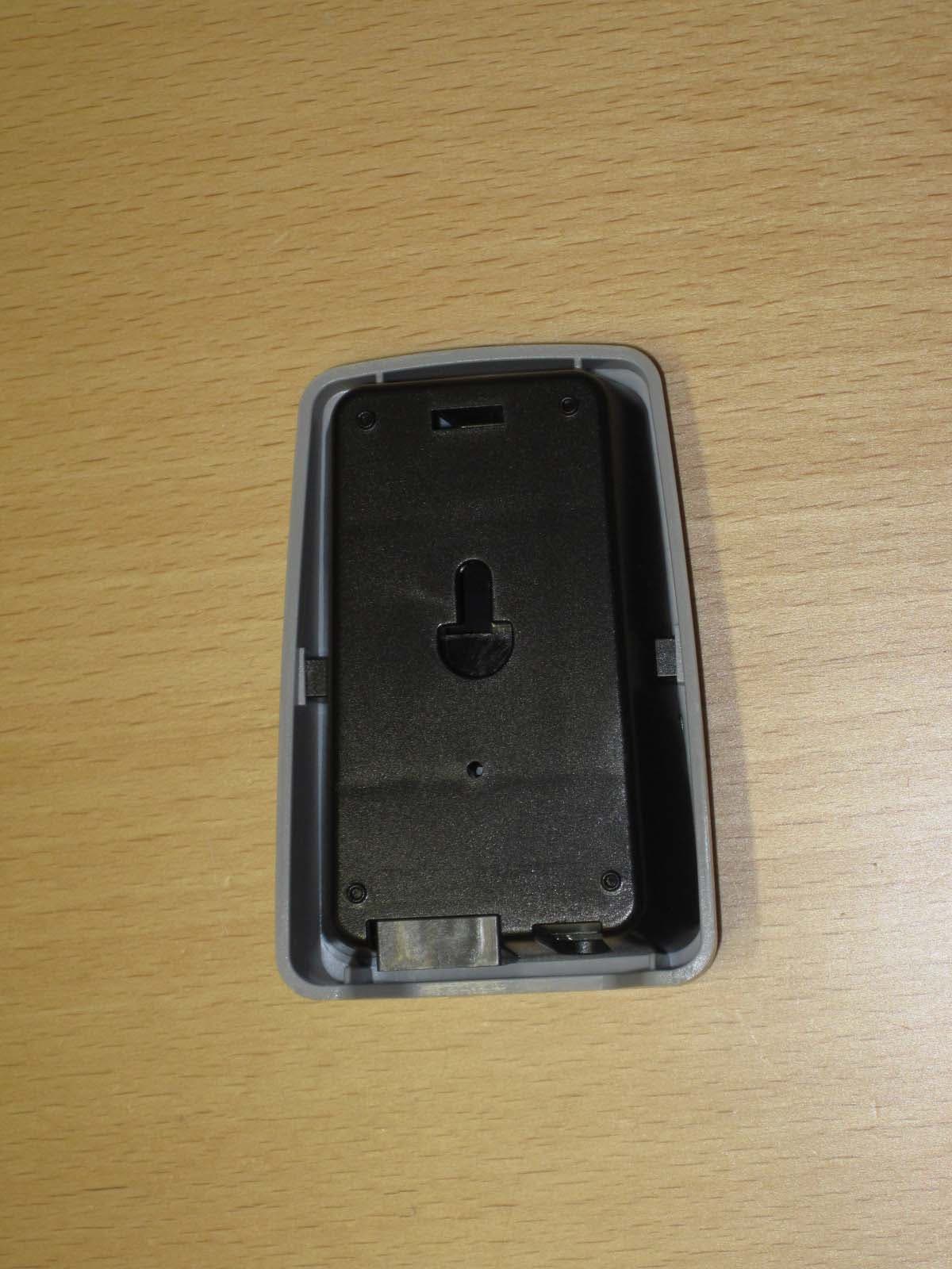
Click to zoom
Application Details
- Equipment Class
- DXX - Part 15 Low Power Communication Device Transmitter
- Date of Grant
- Mar 07, 2012
- Application Purpose
- Original Equipment
- Date of Application
- Mar 07, 2012
- Equipment Note
- Antenna for Heatrecovery units
- Frequency Range
- 904.80000000 - 904.80000000
- Company
- AB CA Ostberg
- Country
- Sweden
Documents & Files
Document Text
Text extracted from the exhibit documents filed with the FCC. Open a document above to read the original.
Users Manual
UL VERSION Installation and directions for use HERU 14 S AC, HERU 19 S AC HERU 35 S AC, HERU 52 S AC UNIT DESCRIPTION . . . . . . . . . . . . . . . . . . . . . . . .3 INSTALLATION AND SECURITY . . . . . . . . . . . . . .4 ”USE” ”SECURITY” ”MOUNTING””WARRANTY” . . . . . .4 ”PLACING” ”FREE SPACE” ”SCHEMATIC DIAGRAM FOR PLACING” . . . . . . . . . . . . .5 STARTING UP THE UNIT . . . . . . . . . . . . . . . . . . . .6 CONTROL DIAGRAMS . . . . . . . . . . . . . . . . . . . . .7 REGULATION FUNCTIONS . . . . . . . . . . . . . . . . . .8 OPERATING THE CONTROL UNIT . . . . . . . . . . . .9 VIEW MODES 1-4 . . . . . . . . . . . . . . . . . . . . . . . .10 MAIN MENU . . . . . . . . . . . . . . . . . . . . . . . . . . . .11 ”FAN SPEED” MENU . . . . . . . . . . . . . . . . . . . . . .11 ”TEMPERATURE” MENU . . . . . . . . . . . . . . . . . . .11 ”BOOST” MENU . . . . . . . . . . . . . . . . . . . . . . . . .11 ”OVERPRESSURE” MENU . . . . . . . . . . . . . . . . . .12 ”WEEK TIMER” MENU . . . . . . . . . . . . . . . . . . . .12 ”UNIT ON/OFF” MENU . . . . . . . . . . . . . . . . . . . .13 ”ALARMS” MENU . . . . . . . . . . . . . . . . . . . . . . . .13 ”SETTINGS” MENU . . . . . . . . . . . . . . . . . . . . . . .14 THE ”SERVICE MENU” . . . . . . . . . . . . . . . . . .14-21 ”FILTER MEASUREMENT” ”AC FAN SETUP” . . . . . . . . . .15 ”DISPLAY CONTRAST” ”BOOST” ”OVERPRESSURE” . . .16 ”ALARM””CO2” . . . . . . . . . . . . . . . . . . . . . . . . . . . . . .17 ”RH” ”HEATER” ”COOLER” . . . . . . . . . . . . . . . . . . . . .18 ”SUPPLY LIMITS” ”REGULATION MODE” ”SUMMER COOLING” . . . . . . . . . . . . . . . . . . . . . . . . . .19 ”FREEZE PROTECTION”FLOW DIRECTION” ”LOAD/SAVE SETTINGS” ”VERSION INFO” . . . . . . . . . . .20 ”DEVICE PAIRS” . . . . . . . . . . . . . . . . . . . . . . . . . . . . . . . .21 OTHER FUNCTIONS . . . . . . . . . . . . . . . . . . . . . .21 SERVICE HERU S . . . . . . . . . . . . . . . . . . . . . . .22-23 ACCESSORIES . . . . . . . . . . . . . . . . . . . . . . . . . . .24 SPARE PARTS . . . . . . . . . . . . . . . . . . . . . . . . . . .25 ERROR DETECTION DIAGRAM . . . . . . . . . . .26-27 ERROR DETECTION . . . . . . . . . . . . . . . . . . . . . . .28 INTERNAL SETTINGS . . . . . . . . . . . . . . . . . . . . .29 CONTENTS DIMENSIONS . . . . . . . . . . . . . . . . . . . . . . . . . . .30 TECHNICAL . . . . . . . . . . . . . . . . . . . . . . . . . . . . .31 SOUND DATA . . . . . . . . . . . . . . . . . . . . . . . .32-33 PRESSURE-FLOW DIAGRAMS . . . . . . . . . . . .34-35 WIRING DIAGRAMS . . . . . . . . . . . . . . . . . . .36-37 TECHNICAL INFORMATION UNIT DESCRIPTION • HERU S is approved according to the standard UL 1812 ”Ducted Heat Recovery Ventilators” and CSA-C22.2 No. 113 ”Fans and Ventilators”. • HERU S is a heat recovery unit (HRV) or an ener- gy recovery unit (ERV). It is designed for supply and exhaust air ventilation combined with heat and cool recovery. • HERU S can be used in homes, offices, apartments etc. where there is a need for: -clean. filtered and fresh air -high temperature efficiency -energy saving -low sound levels -safe operation • HERU S; - has a rotating heat exchanger, of hygroscopic or non-hygroscopic type and is manufactured of alu- minium, placed centrally in the unit. The ERV ex- changer has a humidity efficiency of up to 85%. The HRV exchanger has a temperature efficiency of up to 85%. - has backwardcurved centrifugal fans with main- tenance free external rotor motors, which are con- nected with quick contacts, and are easily to remove for cleaning. - has built-in control for heating/cooling. - can be fitted with a built-in electric heater. - has as standard, disposable bagfilter, class MERV 13. - has a wireless remote controller for the operation and monitoring of the unit. - has a double skinned galvanised sheet steel casing with intermediate insulation. • The HERU S can be mounted in either warm or cold space. • The HERU S is delivered galvanized. • All HERU S are operated via a wireless remote controller which can operate and to preset the re- quired parameters as well as monitor the unit’s status. The operating range is approximately 50 meters/164 feet. The antenna which is placed next to the unit can have the range reduced if there are heavy reinfor- cing bars in the concrete structure and it should then be moved either to a position where the sig- nal is not shielded or nearer to the controller. WARRANTY The warranty is only valid under condition that the HERU S unit is installed, adjusted and has been record by a qualified person according to this ”Installation and directions for use”, and that regular maintenance had been made. NOTE! Östberg Americas Inc. reserve the right to make changes without further notice. 3 This ”Installation and directions for use” contains following products: HERU 14 S AC, HERU 19 S AC, HERU 35 S AC and HERU 52 S AC. IMPORTANT! Please read this manual before installing the unit. HERU 14 S AC HERU 19 S AC HERU 35 S AC HERU 52 S AC INSTALLATION AND SECURITY USE • When installing HERU consideration must be given to any approval authority requirements and recommendations concerning siting, accessibility, electrical connections, etc. • The HERU unit is accessible for the user, accor- ding to IEC 60335-2-40, to by themselves do the service and maintenance, according to this Directions for use. But before this work the unit must be currentless. With reservation according to IEC 60335-2-7.12 ”This appliance is not intended for use by persons (including children) with reduced physical, senso- ry or metal capabilities, or lack of experience and knowledge, unless they have been given supervi- sion or instruction concerning use of the appliance by a person responsible for their safety.” ”Children should be supervised to ensure that they do not play with the appliance.” • The HERU unit should be storage in a sheltered and dry place before installation. • Dimensioned air flow should not exceed 60% of the unit's maximum capacity. • Check at regu…
Text truncated - open the document above for the full version.
External Photos
1(2) External photos - RFLU 2(2)
ID Label/Location Info
8765 D C B A B C D E F 1 2345678 F E A MM Date Pages Doc.file Author Doc.no. Replaces Document type Document description Item Document code and revision 1/1 ---- ---- Drawing XB886-A-01 XB886 RFLU HERU3.0 TYPE LABEL Modifier -- 04.01.2012 Backgroung: White plastic sticker Text: Black FCC ID: A8W-4020527 IC NUMBER: 10098A-4020527 TYPE: RFLU HERU3.0 MODULE MANUFACTURER: Enerpoint Saare Oü Kalevi Põik 7, EE-93815 Kuresaare, Estonia
Internal Photos
1(2) Internal photos - RFLU 2(2)
Test Report
Test report no1116425-2 ed. 2 Page2(20 ) Revision History EditionDateDescription 12011-09-30First release 22011-12-22R eferences and 99% bandwidth measurementfor Industry Canada added Test report no1116425-2 ed. 2 Page3(20 ) CONTENTS Page 1. Client information.............................................................................................................................4 2. Equipment under test (EUT)...........................................................................................................4 2.1 Identification of the EUT according to the manufacturer/client declaration...................4 3. Test specifications...........................................................................................................................5 3. 1 Standards................................................................................................................................5 3.2 Additions, deviations and exclusions from standards.......................................................5 3.3 Test set-up..............................................................................................................................5 3.4 Test conditions.......................................................................................................................5 4. Test summary....................................................................................................................................6 5. Radiated spurious emissions..........................................................................................................7 5.1 Measurement set-up..............................................................................................................7 5.2 Test protocol...........................................................................................................................9 6. Radiated output power...................................................................................................................12 6.1 Test protocol.........................................................................................................................12 6.2 Limit........................................................................................................................................12 7. Band edge compliance..................................................................................................................13 7.1 Test protocol.........................................................................................................................13 8. Conducted emission from AC mains...........................................................................................15 8.1 Measurement set-up............................................................................................................15 8.2 Test protocol.........................................................................................................................16 8. 99% bandwidth...............................................................................................................................17 8.1 Test protocol.........................................................................................................................17 9. Instrumentation list.........................................................................................................................18 Appendix I– Uncertainties summary...............................................................................................19 Appendix II– Photo of the EUT........................................................................................................20 Test report no1116425-2 ed. 2 Page4(20 ) 1.CLIENT INFORMATION The EUT has been tested by request of Company:ABC.A.Östberg Industrigatan 2 774 35 Avesta Sweden Name of contact:Jirry Svedlund 2.EQUIPMENT UNDER TEST(EUT) 2.1 Identification of the EUTaccording to the manufacturer/client declaration Equipment:4020527 Antenna Heru 3.0 Main Unit Type / Model:XT952(Antenna) XT934A (Heru 3.0) Manufacturer:ABC.A. Östberg Rating/Supplying voltage:115 V AC 60 Hz External antenna connector:No FrequencyBand:902– 928 MHz Number of channels:1 (904.8 MHz) Test report no1116425-2 ed. 2 Page5(20 ) 3.TEST SPECIFICATIONS 3.1 Standards FCC 47 CFR part 15 (2011)Subpart B– Unintentional radiators, class B FCC 47 CFR part 15 (2011) Subpart C– Intentional radiators RSS-GEN, Issue 3 (Dec 2010) RSS-210, Issue 8 (Dec 2010) Measurements methods according to ANSI C63.4-2009 and ANSI C63.10-2009 3.2 Additions, deviations and exclusions from standards Noadditions, deviations or exclusions have been made from standard. 3.3 Test set-up Measurement set-upforall testsis described inthe radiatedspurious emissionssection. 3.4Test conditions If not additionally specified, the tests were performed under the following environmental conditions: ParameterNormal Supplying voltage, V115V AC 60Hz Air temperature, o C20 -24°C Test report no1116425-2 ed. 2 Page6(20 ) 4.TEST SUMMARY The results in this report apply only to the sampletested. TestFCC ReferenceIC ReferenceResult Radiated output power15.249RSS-210, A2.9Pass* Band Edge Compliance15.249RSS-210, A2.9Pass Out of band spurious emission, radiated15.249RSS-210, A2.9Pass Conducted disturbance, AC Mains15.207RSS-GENPass 99 % Bandwidth-RSS-GENPass NT = Not Tested NA = Not Applicable *The measured result is below the limit by a margin less than the measurement uncertainty; it is therefore not possible to state compliance based on the 95 % level of confidence. However, the result indicates that compliance is more probable than non-compliance with the specification limit. Test report no1116425-2 ed. 2 Page7(20 ) 5.RADIATED SPURIOUS EMISSIONS 5.1Measurement set-up Test site:Smallanechoic shielded chamber (30– 1000 MHz) In the Small anechoicshieldedchamberthe EUT was placed on a non-metallic table, 1,5m above the floor. The radiated power was measured at a distance of 3 m…
Text truncated - open the document above for the full version.
Test Setup Photos
1(2) TEST SET-UP PHOTOS - RFLU Radiated spurious emission 30-1000 MHz Radiated spurious emission above 1-10 GHz 2(2) Conducted measurements from AC mains
Contact Information
Applicant
Jirry Svedlund(Strategic Technical Development)
Technical Contact
Test Firm
Intertek Semko ABPar Iggstrom
[email protected]+46708750026
Technical Specifications
| # | Rule Parts | Frequency Range | Power Output |
|---|---|---|---|
| 1 | 15C | 904.8 MHz - 904.8 MHz | - |
Other Applications from AB CA Ostberg
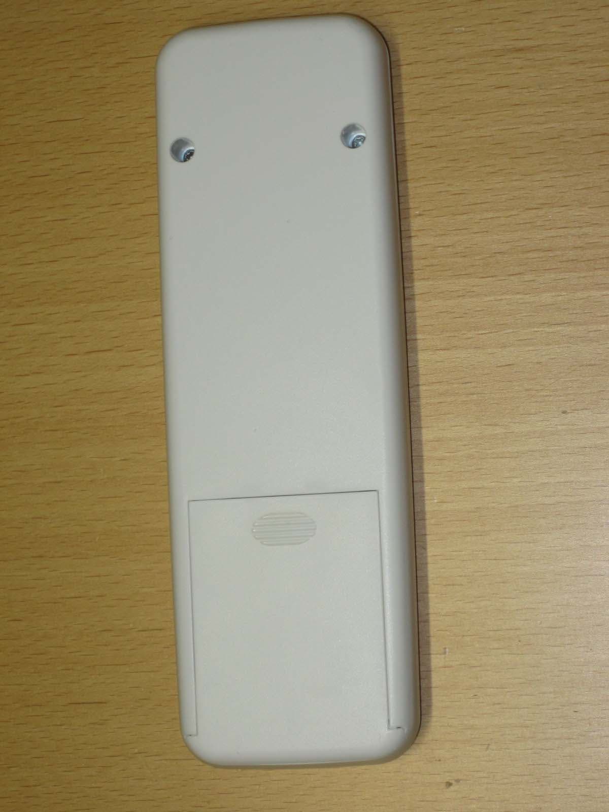
A8W-4020528
Mar 07, 2012Remote Control for Heatrecovery units
Equipment Class
DXX - Part 15 Low Power Communication Device Transmitter