ABMELU81AUser Interface Control Panel with Transmitter
Electrolux Home Products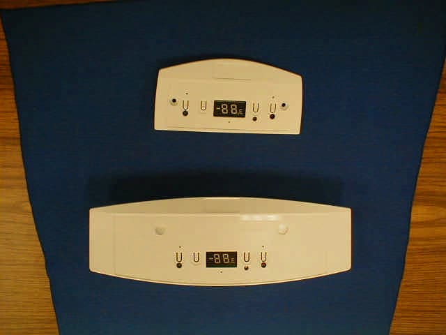
Click to zoom
Application Details
- Equipment Class
- DXX - Part 15 Low Power Communication Device Transmitter
- Date of Grant
- May 09, 2004
- Application Purpose
- Original Equipment
- Date of Application
- May 09, 2004
- Equipment Note
- User Interface Control Panel with Transmitter
- Frequency Range
- 915.00000000 - 915.00000000
- Company
- Electrolux Home Products
- Country
- United States
Documents & Files
Document Text
Text extracted from the exhibit documents filed with the FCC. Open a document above to read the original.
Users Manual
TABLE OF CONTENTS TX FCC ID: ABMELU81A Note: The user interface (Control Panel) and receiver( Freezer Mate) have been tested and found to comply with the limits for a Class B digital device, pursuant to part 15 of the FCC Rules. These limits are designed to provide reasonable protection against harmful interference in a residential installation. This equipment generates, uses, and can radiate radio frequency energy and, if not installed and used in accordance with the instructions may cause harmful interference to radio communications. However, there is no guarantee that interference will not occur in a particular installation. If this equipment does cause harmful interference to radio or television reception, which can be determined by turning the equipment off and on, the user is encouraged to try to correct the interference by one or more of the following measures: - Reorient or relocate the receiving antenna. - Increase the separation between the equipment and receiver. - Connect the equipment into an outlet on a circuit different from that to which the receiver is connected. - Consult the dealer or an experienced radio/TV technician for help. Changes or modifications to the transmitter or receiver not expressly approved by the party responsible for compliance could void the user’s authority to operate the equipment. BATTERY INSTALLATION This system requires the installation of a standard 9-volt battery (not included). The system will not function as intended, without the battery being installed. Please locate the battery holder as described in the following illustrations. Remove cover(S), hook up the connector, slide battery and excess wire into the compartment and replace covers. Figure: Battery Installation for Upright Style Freezer. Figure: Battery Installation for Chest Type Freezer Figure: User Interface (Control Panel). TEMPERATURE CONTROL TEMPERATURE SETTING: The desired temperature inside the freezer can be set using the UP (▲) and DOWN (▼) buttons on the user interface, located on the door of the freezer. Press either the UP or DOWN buttons once to display the current setting. You may now use the UP and DOWN buttons to change the temperature setting to one which suits your needs. The range of settings is -10°F to 10°F( -24ºC to -12ºC ) (See figure 1and 2). The display will return to showing the temperature of the cabinet after five seconds of inactivity. You may also turn off the freezer by pressing the UP button when at temperature setting 10°F ( -12ºC) The display will read “0FF” (figure 3). The freezer will not cool anything while it is on “0FF” position. Temperature Mode Change: Temperature display can be changed from ºF to ºC to ºF by pressing the ALARM RESET and DOWN arrow simultaneously until it beeps. The display will change to the other mode. Note : The door light will continue to operate. The freezer also still has electrical power and so should be disconnected from the outlet before being cleaned or moved. Figure: 1 Figure: 2 Figure: 3 QUICK FREEZE: Quick Freeze enables the compressor to run continuously to help cool large quantities of warm (room temperature) foods faster. Always cool down hot foods to room temperature before placing it in the freezer. Use this feature just prior to adding large quantities of unfrozen foods (not to exceed 3 pounds per cubic foot of freezer space). To activate the Quick Freeze feature, push the QUICK FREEZE button. The buzzer will beep once and the display will now read “FF” (Figure 4), indicating that Quick Freeze has begun. For your convenience, Quick Freeze will automatically turn off after a period of 72 hours and the freezer will return to the previous temperature setting. You may deactivate Quick Freeze at any time by pressing the QUICK FREEZE button. The display will return to showing the current temperature inside the freezer and the buzzer will beep once. Figure: 4 DISPLAY LOCKOUT: Press and hold the ALARM RESET key until the buzzer beeps to activate or deactivate the Display Lockout feature which prevents the user from accidentally changing the temperature and quick freeze settings. The buzzer beeps and “LOC” (Stands for LOCK, See figure 5) will be displayed for 3 seconds indicating that it is locked. Once in lockout when a key is pressed, the “LOC” will be displayed for 3 seconds. When the lockout is deactivated, “UL” (Stands for UNLOCK, See figure 6) will be displayed for 1 second. Figure: 5 Figure: 6 ALARM FUNCTIONS TEMPERATURE ALARM: If the cabinet temperature rises to a level above 23ºF (-5ºC), a high temperature alarm will be activated. The buzzer will beep every 5 seconds, the red alarm light will glow and the display will flash. This will continue till the problem is determined, corrected and temperature once again drops to a level below 23ºF (-5ºC). You may stop the buzzer by pressing the ALARM RESET button. To also stop the display from flashing press the ALARM RESET button again. Temperature Alarm will reactivate itself upon reaching a safe temperature. DOOR / LID AJAR ALARM: The door/lid alarm will activate if it is ajar for more than five minutes. The buzzer will beep every five seconds, the red alarm light will glow and the display will alternate between “d” (Stands for Door/Lid, See figure 7) and the cabinet temperature. Press the ALARM RESET button to turn the buzzer off. The display will keep flashing and the red light will stay on. Close the door/lid of the freezer to return it to normal operation. Figure: 7 LOW / NO BATTERY ALARM: The Low/No battery alarm will activate when the power level of the battery becomes low. The display will alternate between “b” (Stands for Battery, See figure 8) and the cabinet temperature, the red alarm light will become illuminated and the buzzer will beep every five seconds. To stop the buzzer, press the “ALARM RESET” button. The red alarm light will remain on and the display will continue to flash until a new battery is installed. This same alarm will activate if there …
Text truncated - open the document above for the full version.
ID Label/Location Info
Figure: FCC label TX FCC ID: ABMELU81A This device complies with part 15 of the FCC rules. Operation is subject to the following conditions: 1. this device may not cause any harmful interference, and 2. this device must accept any interference received including interference that may cause undesired operation. P/N 216979800
ID Label/Location Info
FCC Disclaimer on the finish products: The location and the sample of the label are attached below. Figure: FCC label Figure: Upright style freezer FCC ID: ABMELU81A This device complies with part 15 of the FCC rules. Operation is subject to the following conditions: 1. this device may not cause any harmful interference, and 2. this device must accept any interference received including interference that may cause undesired operation. FCC ID: Figure: Upright style freezer. Zoomed view of FCC ID label location. Figure: Chest type freezer. FCC ID: FCC ID: Figure: Chest type freezer. Zoomed view of the FCC ID label location. FCC ID:
Operational Description
Description of AidPad Transmitter The transmitter of the Aidpad is based on a Microchip rfPIC12F675H radio. It operates at 915MHz using ASK modulation. There is a single operating mode during which the unit transmits once every minute. Every minute the unit sends out 5 packets containing 15 bytes (including preamble). The data is Manchester Encoded and runs at a bit rate of 1600 bits per second. The 5 packets are sent back-to-back then the unit rests for the remainder of the minute. The antenna of the transmitter is printed on the board. It is 3¼” long and runs down the side of the board. Only the area immediately around the antenna is devoid of a ground plane. The rest of the PCB contains ground plane pours both on the top and bottom. The antenna incorporates a double-pi network to reduce sideband emissions. The ground plane connection is fed through a wire to the power supply contained on a separate control in the freezer appliance. The wire is approximately 8 feet long.
Test Report
Electrolux Home Products Application For Certification User Interface with Transmitter FCC ID: ABMELU81A April 28, 2004 Intertek ETL SEMKO 7250 Hudson Boulevard, Suite 100, Oakdale, MN 51228 Telephone 651-730-1188, Fax 651-730-1282 Home Page www.intertek.com CONTENTS 1.0 GENERAL DESCRIPTION..........................................................................1 1.1 Related Submittals Grants.....................................................................................1 1.2 Product Description............................................................................................1 1.3 Test Methodology..............................................................................................1 1.4 Test Facility.....................................................................................................1 2.0 SYSTEM TEST CONFIGURATION..............................................................2 2.1 Justification......................................................................................................2 2.2 EUT Setup.......................................................................................................2 2.3 EUT Exercising Software.....................................................................................2 2.4 Special Accessories............................................................................................2 2.5 Equipment Modification.......................................................................................2 2.6 Support Equipment List and Description...................................................................2 2.7 Test Configuration Block Diagrams.........................................................................3 3.0 TEST RESULTS.........................................................................................4 3.1 Field Strength of Fundamental and Harmonics Emissions, FCC 15.249(a)..........................5 3.2 Field Strength of Harmonics Emissions, FCC 15.249(a), 15.205.....................................6 3.2 Field Strength of Harmonics Emissions, FCC 15.249(a), 15.205.....................................7 3.3 Out of Band Spurious Emissions, FCC 15.249(c), 15.209............................................11 3.4 Bandwidth of Emissions.....................................................................................14 3.5 Line Conducted Emissions, FCC 15.207................................................................15 3.6 Test Procedure................................................................................................18 3.7 Field Strength Calculation..................................................................................19 4.0 TEST EQUIPMENT..................................................................................20 FCC ID: ABMELU81A April 2004 Page 1 of 20 1.0 GENERAL DESCRIPTION 1.1 Related Submittals Grants This is single application of the Electrolux Home Products User Interface with Transmitter for Certification under FCC Part 15, Subpart C. There are no other simultaneous applications. The Receiver portion will be verified under Declaration of Conformity. 1.2 Product Description User Interface with Transmitter is a RF transmitter operating in 915MHz. The intended use of the User Interface with Transmitter is to generate and transmit a RF signal with freezer status data to receiver. User Interface with Transmitter powered at 5VDC. Antenna Description: Integrated antenna Sample Submitted: April 8, 2004 Test Work Started: April 8, 2004 Test Work Completed: April 12, 2004 1.3 Test Methodology Emission measurements were performed according to the procedures in ANSI C63.4-2000. All field strength radiated emissions measurements were performed in the semi-anechoic chamber, and for each scan, the procedure for maximizing emissions in Appendices D and E were followed. All field strength radiated tests were performed at an antenna to EUT distance of 3 meters, unless stated otherwise in the "Justification Section" of this Application. 1.4 Test Facility The test site facility used to collect the radiated and conducted measurement data is located at 7250 Hudson Blvd., Suite 100, Oakdale, Minnesota. This test facility has been fully described in a report dated on March 2003 submitted to FCC. Please reference the site registration number: 90706, dated April 18, 2003. FCC ID: ABMELU81A April 2004 Page 2 of 20 2.0 SYSTEM TEST CONFIGURATION 2.1 Justification N/A 2.2 EUT Setup For simplicity of testing, the transmitter was wired to transmit continuously and tested with no plastic enclosure. The freezer Electronic Control Unit including the Power Supply (ECU) was assembled on the test fixture to provide data and 5VDC for the User Interface with Transmitter. 2.3 EUT Exercising Software N/A 2.4 Special Accessories There are no special accessories necessary for compliance of these products. 2.5 Equipment Modification No modifications were installed during the testing. 2.6 Support Equipment List and Description Freezer Electronic Control Unit including the Power Supply (ECU) assembled on the test fixture by Electrolux Home Products. FCC ID: ABMELU81A April 2004 Page 3 of 20 2.7 Test Configuration Block Diagrams The EUT was setup as tabletop equipment. The EUT was powered at 5VDC from the Electronic Control Unit Power Supply (ECU). Field Strength Measurements FCC ID: ABMELU81A April 2004 Page 4 of 20 3.0 TEST RESULTS Data is included for the worst case configuration (the configuration which resulted in the highest emission levels). A sample calculation, configuration photographs, data tables and graphical representations of the emissions are included. The EUT is intended for operation under the requirements of Part 15 Subpart C. Specific test requirements include the following: 47 CFR 15.249(a)(b) Field Strength of Fundamental 47 CFR 15.249(a)(b), 15.205 Field Strength of Harmonics 47 CFR 15.249(c), 15.209 Out of Band Spurious Emissions Bandwidth of Emissions 47 …
Text truncated - open the document above for the full version.
Test Setup Photos
CONFIGURATION PHOTOS Radiated Emissions Test Configuration Radiated Emissions Test Configuration Radiated Emissions Test Configuration Line Conducted Emissions Test Configuration Line Conducted Emissions Test Configuration
Contact Information
Applicant
Roger Hetler(Sr. Approvals Engineer)
Technical Contact
Electrolux Home ProductsMizanur Chowdhury
[email protected]320-420-4233
701 33rd Avenue North · St. Cloud, Minnesota · United States
Non-Technical Contact
Electrolux Home ProductsRoger Hetler
[email protected]615-382-1834
Test Firm
Intertek Testing ServicesUri Spector
Technical Specifications
| # | Rule Parts | Frequency Range | Power Output |
|---|---|---|---|
| 1 | 15C | 915 MHz - 915 MHz | - |
Other Applications from Electrolux Home Products
ABM964T01
Oct 15, 1984Magnetrons: Hitachi 2M53, 2M53A, 2M115; Litton L5673; Matsushita 2M188G; Toshiba 2M115V Alternate Magnetrons: Panasonic 2M167-M10; Toshiba 2M172AJ; Hitachi 2M107A Alternate Magnetrons: Samsung OM75
Equipment Class
8CD - Unkown (From ALTOS)