AK8-CBK-WA02Wireless LAN Adapter
Sony Group Corporation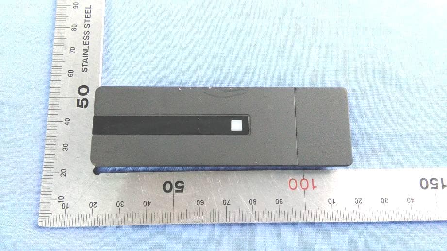
Click to zoom
Application Details
- Equipment Class
- NII - Unlicensed National Information Infrastructure TX
- Date of Grant
- Aug 18, 2015
- Application Purpose
- Original Equipment
- Date of Application
- Aug 18, 2015
- Equipment Note
- Wireless LAN Adapter
- Frequency Range
- 5745.00000000 - 5825.00000000
- Company
- Sony Group Corporation
- Country
- Japan
Documents & Files
Document Text
Text extracted from the exhibit documents filed with the FCC. Open a document above to read the original.
Users Manual
CBK-WA02 (GB/FR) 4-576-755-11 (1) English Before operating the unit, please read this manual thoroughly and retain it for future reference. For the customers in the U.S.A. If you have any questions about this product, you may call; Sony Customer Information Service Center 1-800-222-7669 or http://www.sony.com/ This device complies with Part 15 of the FCC Rules. Operation is subject to the following two conditions: (1) This device may not cause harmful interference, and (2) this device must accept any interference received, including interference that may cause undesired operation. FCC Radiation Exposure Statement: The available scientific evidence does not show that any health problems are associated with using low power wireless devices. There is no proof, however, that these low power wireless devices are absolutely safe. Low power Wireless devices emit low levels of radio frequency energy (RF) in the microwave range while being used. Whereas high levels of RF can produce health effects (by heating tissue), exposure to low level RF that does not produce heating effects causes no known adverse health effects. Many studies of low level RF exposures have not found any biological effects. Some studies have suggested that some biological effects might occur, but such findings have not been confirmed by additional research. The CBK-WA02 has been tested and found to comply with the Federal Communications Commission (FCC) guidelines on radio frequency energy (RF) exposures. This device and its antenna(s) must not be co-located or operating with any other antenna or transmitter. Users are not permitted to modify this transmitter device. Any unauthorized changes made to this device could void your authority to operate this device. Changes or modifications not expressly approved by the party responsible for compliance could void the user’s authority to operate the equipment. 5.15-5.25GHz band is restricted to indoor operations only. Frequency Tolerance: 820 ppm This transmitter must not be co-located or operated in conjunction with any other antenna or transmitter. For the customers in the U.S.A. and Canada This device complies with Part 15 of FCC Rules and RSS-Gen of IC Rules. Operation is subject to the following two conditions: (1) this device may not cause interference, and (2) this device must accept any interference, including interference that may cause undesired operation of this device. This equipment complies with FCC/IC radiation exposure limits set forth for uncontrolled equipment and meets the FCC radio frequency (RF) Exposure Guidelines and RSS-102 of the IC radio frequency (RF) Exposure rules. This equipment should be installed and operated with at least 20cm and more between the radiator and person’s body (excluding extremities: hands, wrists, feet and ankles). This device complies with Part 15 of FCC Rules and Industry Canada’s licence- exempt RSSs. Operation is subject to the following two conditions: (1) this device may not cause harmful interference, and (2) this device must accept any interference received, including interference that may cause undesired operation. The available scientific evidence does not show that any health problems are associated with using low power wireless devices. There is no proof, however, that these low power wireless devices are absolutely safe. Low power Wireless devices emit low levels of radio frequency energy (RF) in the microwave range while being used. Whereas high levels of RF can produce health effects (by heating tissue), exposure of low-level RF that does not produce heating effects causes no known adverse health effects. Many studies of low-level RF exposures have not found any biological effects. Some studies have suggested that some biological effects might occur, but such findings have not been confirmed by additional research. CBK-WA02 has been tested and found to comply with FCC/ IC radiation exposure limits set forth for an uncontrolled environment and meets the FCC radio frequency (RF) Exposure Guidelines and RSS-102 of the IC radio frequency (RF) Exposure rules. Data transmission is always initiated by software, which is the passed down through the MAC, through the digital and analog baseband, and finally to the RF chip. Several special packets are initiated by the MAC. These are the only ways the digital baseband portion will turn on the RF transmitter, which it then turns off at the end of the packet. Therefore, the transmitter will be on only while one of the aforementioned packets is being transmitted. In other words, this device automatically discontinue transmission in case of either absence of information to transmit or operational failure. For the customers in Canada The term “IC:” before the radio certification number only signifies that Industry Canada technical specifications were met. 5150-5250 MHz band is restricted to indoor operation only. High-power radars are allocated as primary users (i.e. priority users) of the bands 5250-5350 MHz and 5650-5850 MHz and that these radars could cause interference and/or damage to LE-LAN devices. For the customers in Europe Notice for customers: the following information is only applicable to equipment sold in Countries applying EU directives. BulgarianС настоящето Сони Корпорация декларира, че този безжичен LAN адаптер CBK-WA02 отговаря на основните изисквания и другите съответстващи клаузи на Директива 1999/5/ЕС. Подробности може да намерите на Интернет страницата : http://www.compliance.sony.de/. CzechSony Corporation tímto prohlašuje, že tento CBK-WA02/adaptér bezdrátové sítě LAN je ve shodě se základními požadavky a dalšími příslušnými ustanoveními směrnice 1999/5/ES. Podrobnosti lze získat na následující URL: http://www.compliance.sony.de/ DanishUndertegnede, Sony Corporation, erklærer herved, at denne CBK-WA02/trådløse LAN-adapter overholder de væsentlige krav og øvrige relevante krav i direktiv 1999/5/EF. For yderligere information gå ind på følgende hjemmeside: http://…
Text truncated - open the document above for the full version.
Cover Letter(s)
Federal Communication Commission Equipment Authorization Division, Application Processing Branch 7435 Oakland Mills Road Columbia, MD 21048 UNII Device Declaration Letter To whom it may concern: We have declared below featured for FCC equipment authorization, Device FCC ID:AK8-CBK-WA02 DFS Device: Master Client with Radar detection capability N/A Client without radar detection capability (1) Active / Passive Scanning , adhoc mode access point capability Frequency Band (MHz) Active Scanning (the device can transmit a probe (beacon)) passive scanning (where the device is can listen only with no probes) Ad Hoc Mode or WIFI Direct capability Access point capability 2412 - 2462 Yes No Yes No Yes No Yes No 5180 - 5240 Yes No Yes No Yes No Yes No 5260 - 5320 Yes No Yes No Yes No Yes No 5500 - 5700 Yes No Yes No Yes No Yes No 5745 - 5825 Yes No Yes No Yes No Yes No (2) Country code selection ability Yes No If yes, pls explain how it was implemented: (3) Meet 15.202 requirement Yes No pls check below : A master device is defined as a device operating in a mode in which it has the capability to transmit without receiving an enabling signal. In this mode it is able to select a channel and initiate a network by sending enabling signals to other devices A client device is defined as a device operating in a mode in which the transmissions of the device are under control of the master. A device in client mode is not able to initiate a network. (4) For client devices that have software configuration control to operate in different modes (active scanning in some and passive scanning in others) in different bands (devices with multiple equipment classes or those that operate on non-DFS frequencies) or modular devices which configure the modes of operations through software, the application must provide software and operations description on how the software and / or hardware is implemented to ensure that proper operations modes cannot be modified by end user or an installer. Apply Does not apply (If apply, pls help to provide explanation on it was implement, and how software was controlled) Name: Yutaka FUJITA Address: 1-7-1 KonanMinato-kuTokyo108-0075Japan E-mail: [email protected] Telephone: 81-3-6748-4405 Fax: 81-3-6748-4409
Cover Letter(s)
Sony Corporation, Head Office 1-7-1 Konan Minato-ku, Tokyo, 108-0075 Japan Compliance Assurance Section, CS Promotion Department, Quality & Operation Division, Digital Imaging Business Group Telephone +81-3-6748-4405 Fax +81-3-6748-4409 File=Declaration Letter of Software Security Requirements For U-NII Federal Communication Commission Equipment Authorization Division, Application Processing Branch 7435 Oakland Mills Road Columbia, MD21048 2015-08-07 Attn: Office of Engineering and Technology Subject: Attestation Letter regarding UNII devices FCC ID: AK8-CBK-WA02 Software security questions and answers per KDB 594280 D02: Software Security description – General Description 1 Describe how any software/firmware update will be obtained, downloaded, and installed. Software that is accessed through manufacturer’s website or device’s management system, must describe the different levels of security. We do not release the firmware on our website for downloading. Our direct host manufacturer (OEM) can request the firmware from us and it will be made available via secure server. 2 Describe all the radio frequency parameters that are modified by any software/firmware without any hardware changes. Are these parameters in some way limited, such that, it will not exceed the authorized parameters? Radio frequency parameters are limited by US regulatory domain and country code to limit frequency and transmit power levels. These limits are stored in non-volatile memory by the module manufacturer at the time of production. They will not exceed the authorized values. 3 Describe in detail the authentication protocols that are in place to ensure that the source of the software/firmware is legitimate. Describe in detail how the software is protected against modification The firmware is installed on each single module during manufacturing process. The correct firmware is verified and installed by the module manufacturer. 4 Describe in detail the verification protocols in place to ensure that installed software/firmware is legitimate Only correct firmware is stored in SROM (see #3). 5 Describe in detail the verification protocols in place to ensure that installed software/firmware is legitimate Only correct firmware is stored in SROM (see #3). 6 For a device that can be configured as a master and client (with active or passive scanning), explain how the device ensures compliance for each mode? In particular if the device acts as master in some band of operation and client in another; how is compliance ensured in each band of operation? The device ensures the compliance by checking the configured parameter and operation values according to the country code in each band. Sony Corporation, Head Office 1-7-1 Konan Minato-ku, Tokyo, 108-0075 Japan Compliance Assurance Section, CS Promotion Department, Quality & Operation Division, Digital Imaging Business Group Telephone +81-3-6748-4405 Fax +81-3-6748-4409 File=Declaration Letter of Software Security Requirements For U-NII Software Security description – Third-Party Access Control 1 How is unauthorized software/firmwarechanges prevented? Unauthorized firmware is not accepted by the firmware update process. See General Description #5, #3 2 Is it possible for third parties to load device drivers that could modify the RF parameters, country of operation or other parameters which impact device compliance? If so, describe procedures to ensure that only approved drivers are loaded. No, third parties don’t have the capability to modify the RF parameters. 3 Explain if any third parties have the capability to operate a US sold device on any other regulatory domain, frequencies, or in any manner that is in violation of the certification. No, third parties don’t have the capability to access and change radio parameters. US sold modules are factory configured to US. 4 What prevents third parties from loading on -US versions of the software/firmware on the device? No, third parties don’t loading software/firmware on the device. 5 For modular devices, describe how authentication is achieved when used with different hosts. The module is not available for sale or installation outside of company licensing agreements. Modules are always installed in host systems in a factory by end integrators (OEM) responsible for loading authorized software. Software Security description – USER CONFIGURATION GUID 1 To whom is the UI accessible? (Professional installer, end user, other.) We don’t have UI. a. What parameters are viewable to the professional installer/end user? We don’t have UI. b. What parameters are accessible or modifiable to the professional installer? i. Are the parameters in some way limited, so that the installers will not enter parameters that exceed those authorized? ii. What controls exist that the user cannot operate the device outside its authorization in the U.S.? We don’t have UI. c. What configuration options are available to the end-user? i. Are the parameters in some way limited, so that the installers will not enter parameters that exceed those authorized? ii. What controls exist that the user cannot operate the device outside its authorization in the U.S.? We don’t have UI. Sony Corporation, Head Office 1-7-1 Konan Minato-ku, Tokyo, 108-0075 Japan Compliance Assurance Section, CS Promotion Department, Quality & Operation Division, Digital Imaging Business Group Telephone +81-3-6748-4405 Fax +81-3-6748-4409 File=Declaration Letter of Software Security Requirements For U-NII d. Is the country code factory set? Can it be changed in the UI? i. If so, what controls exist to ensure that the device can only operate within its authorization in the U.S.? We don’t have UI. e. What are the default parameters when the device is restarted? We don’t have UI. 2 Can the radio be configured in bridge or mesh mode? If yes, an attestation may be required. Further information is available in KDB Publication 905462 D02. Not supported 3 For a device that can be configured as a master an…
Text truncated - open the document above for the full version.
External Photos
Report No.: C150424Z02 Page 1/2 External Photos of EUT Report No.: C150424Z02 Page 2/2 .
ID Label/Location Info
B&P IPELA SEKKEI1BU 05/14/2015 A.UKAI DI CORE MD2 05/14/2015 T.WATANABE B&P IPELA SEKKEI1BU 05/14/2015 A.UKAI DI CORE MD2 05/14/2015 T.WATANABE B&P IPELA SEKKEI1BU 04/28/2015 A.UKAI DI CORE MD2 04/24/2015 T.WATANABE
Internal Photos
Report No.: C150424Z02 Page 1/1 Internal Photos of EUT Antenna RF Module
RF Exposure Info
Compliance Certification Services Inc. Date of Issue: August 18, 2015 FCC ID:AK8-CBK-WA02 Report No .: C150504S05-SF Page 1 of 125 This report shall not be reproduced except in full, without the written approval of Compliance Certification Services. ANSI/IEEE Std. C95.1-1992 In accordance with the requirements of FCC Report and Order: ET Docket 93-62;FCC 47 CFR Part 2 ( 2.1093) FCC SAR TEST REPORT For Product Name: Wireless LAN Adapter Brand Name: SONY Model No.: CBK-WA02 Series Model: N/A Test Report Number: C150504S05-SF Issued for Sony Corporation 1-7-1 Konan Minato-ku Tokyo 108-0075 Japan Issued by Compliance Certification Services Inc. Kun shan Laboratory No.10 Weiye Rd., Innovation park, Eco&Tec, Development Zone, Kunshan City, Jiangsu, China TEL: 86-512-57355888 FAX: 86-512-57370818 Note: This report shall not be reproduced except in full, without the written approval of Compliance Certification Services Inc. This document may be altered or revised by Compliance Certification Services Inc. personnel only, and shall be noted in the revision section of the document. The client should not use it to claim product endorsement by A2LA or any government agencies. The test results in the report only apply to the tested sample. Compliance Certification Services Inc. Date of Issue: August 18, 2015 FCC ID:AK8-CBK-WA02 Report No .: C150504S05-SF Page 2 of 125 This report shall not be reproduced except in full, without the written approval of Compliance Certification Services. Revision History Revision REPORT NO. Date Page Revised Contents Original C150504S05-SF June 8, 2015 N/A N/A 01 C150504S06-SF August 13, 2015 26 to 31Update output power form 38 to 39 Add simultaneous transmission Form 02 C150504S06-SF August 18, 2015 All report Add KDB248227D01v02r01 related description Compliance Certification Services Inc. Date of Issue: August 18, 2015 FCC ID:AK8-CBK-WA02 Report No .: C150504S05-SF Page 3 of 125 This report shall not be reproduced except in full, without the written approval of Compliance Certification Services. TABLE OF CONTENTS 1. CERTIFICATE OF COMPLIANCE (SAR EVALUATION) ........................................................... 4 2. EUT DESCRIPTION .................................................................................................................... 5 3. REQUIREMENTS FOR COMPLIANCE TESTING DEFINED BY THE FCC ................................ 6 4. TEST METHODOLOGY .............................................................................................................. 6 5. TEST CONFIGURATION ............................................................................................................ 6 6. DOSIMETRIC ASSESSMENT SETUP ........................................................................................ 7 6.1 MEASUREMENT SYSTEM DIAGRAM ........................................................................................................... 8 6.2 SYSTEM COMPONENTS ............................................................................................................................... 9 7. EVALUATION PROCEDURES ................................................................................................. 12 7.1 DATA EVALUATION ..................................................................................................................................... 12 7.2 SAR EVALUATION PROCEDURES ............................................................................................................. 14 7.3 SPATIAL PEAK SAR EVALUATION ............................................................................................................. 15 8. EXPOSURE LIMIT .................................................................................................................... 16 9. EUT ARRANGEMENT .............................................................................................................. 17 9.1 BODY-SUPPORTED DEVICE ...................................................................................................................... 17 9.2 USB DONGLE PROCEDURES .................................................................................................................... 17 10. MEASUREMENT RESULTS ..................................................................................................... 18 10.1 TEST LIQUIDS CONFIRMATION ............................................................................................................... 18 10.2 LIQUID MEASUREMENT RESULTS .......................................................................................................... 19 10.3 SYSTEM PERFORMANCE CHECK ........................................................................................................... 20 10.4 SYSTEM PERFORMANCE CHECK RESULTS .......................................................................................... 21 11. MEASUREMENT UNCERTAINTY ............................................................................................ 22 12. EUT TUNE-UP PROCEDURES AND TEST MODE ................................................................................ 23 12.1 ANTENNA POSITION ................................................................................................................................. 32 12.2 EUT SETUP PHOTO ................................................................................................................................... 33 12.3 SAR MEASUREMENT RESULTS ............................................................................................................... 34 12.4 REPEATED SAR MEASUREMENT ............................................................................................................ 38 13. EUT PHOTO ............................................................................................................................. 39 14. EQUIPMENT LIST & CALIBRATION STATUS ........................................................…
Text truncated - open the document above for the full version.
RF Exposure Info
Compliance Certification Services Inc. Date of Issue: August 18, 2015 FCC ID:AK8-CBK-WA02 Report No .: C150504S05-SF Page 1 of 16 WiFi 802.11b-Body Horizontal Up Chain 0 Middle CH6 ............................................................... 2 WiFi 802.11b-Body Horizontal Down Chain 0 Middle CH6 ......................................................... 3 WiFi 802.11b-Body Horizontal Up Chain 1 High CH11 ................................................................ 4 WiFi 802.11b-Body Horizontal Down Chain 1 High CH11 ........................................................... 5 WiFi 802.112.4GHz n20-Body Horizontal Chain 0+1 Up High CH11 ......................................... 6 WiFi 802.112.4GHz n20 -Body Horizontal Chain 0+1 Down High CH11 .................................. 7 WiFi 802.11a-Body Horizontal Up Chain 0 CH64 .......................................................................... 8 WiFi 802.11a-Body Horizontal Up Chain 1 CH64 .......................................................................... 9 WiFi 802.11 5.3G n40 -Body Horizontal Up Chain 0+1 CH54 ................................................... 10 WiFi 802.11a-Body Horizontal Up Chain 0 CH140 ....................................................................... 11 WiFi 802.11a-Body Horizontal Down Chain 0 CH140 ................................................................. 12 WiFi 802.11a-Body Horizontal Up Chain 1 CH140 ...................................................................... 13 WiFi 802.11a-Body Horizontal Down Chain 1 CH140 ................................................................. 14 WiFi 802.11 5.5G n20 -Body Horizontal Up Chain 0+1 CH140 ................................................. 15 WiFi 802.11 5.8G n20 -Body Horizontal Up Chain 0+1 CH165 ................................................. 16 Compliance Certification Services Inc. Date of Issue: August 18, 2015 FCC ID:AK8-CBK-WA02 Report No .: C150504S05-SF Page 2 of 16 Test Laboratory: Compliance Certification Services Inc. Date: 6/6/2015 WiFi 802.11b-Body Horizontal Up Chain 0 Middle CH6 DUT: Wireless LAN Adapter; Type: CBK-WA02 Communication System: UID 0, IEEE 802.11b (0); Communication System Band: ISM 2.4GHz Band; Frequency: 2437 MHz;Duty Cycle: 1:1 Medium parameters used: f = 2437 MHz; σ = 1.945 S/m; ε r = 51.672; ρ = 1000 kg/m 3 Room Ambient Temperature: 22°C; Liquid Temperature: 21.5°C Phantom section: Flat Section Measurement Standard: DASY5 (IEEE/IEC/ANSI C63.19-2007) DASY Configuration: • Probe: EX3DV4 - SN3798; ConvF(6.82, 6.82, 6.82); Calibrated: 7/28/2014; • Sensor-Surface: 2mm (Mechanical Surface Detection) • Electronics: DAE4 Sn1245; Calibrated: 7/22/2014 • Phantom: ELI v4.0; Type: QDOVA001BB; Serial: TP:1102 • DASY52 52.8.8(1222); • SEMCAD X Version 14.6.10 (7331) WiFi/Up Chain 0 Middle CH6/Area Scan (7x12x1): Measurement grid: dx=12mm, dy=12mm Maximum value of SAR (measured) = 0.596 W/kg WiFi/Up Chain 0 Middle CH6/Zoom Scan (7x7x7)/Cube 0: Measurement grid: dx=5mm, dy=5mm, dz=5mm Reference Value = 11.34 V/m; Power Drift = 0.12 dB Peak SAR (extrapolated) = 1.11 W/kg SAR(1 g) = 0.533 W/kg; SAR(10 g) = 0.246 W/kg Maximum value of SAR (measured) = 0.815 W/kg 0 dB = 0.815 W/kg = -0.89 dBW/kg Compliance Certification Services Inc. Date of Issue: August 18, 2015 FCC ID:AK8-CBK-WA02 Report No .: C150504S05-SF Page 3 of 16 Test Laboratory: Compliance Certification Services Inc. Date: 6/6/2015 WiFi 802.11b-Body Horizontal Down Chain 0 Middle CH6 DUT: Wireless LAN Adapter; Type: CBK-WA02 Communication System: UID 0, IEEE 802.11b (0); Communication System Band: ISM 2.4GHz Band; Frequency: 2437 MHz;Duty Cycle: 1:1 Medium parameters used: f = 2437 MHz; σ = 1.945 S/m; ε r = 51.672; ρ = 1000 kg/m 3 Room Ambient Temperature: 22°C; Liquid Temperature: 21.5°C Phantom section: Flat Section Measurement Standard: DASY5 (IEEE/IEC/ANSI C63.19-2007) DASY Configuration: • Probe: EX3DV4 - SN3798; ConvF(6.82, 6.82, 6.82); Calibrated: 7/28/2014; • Sensor-Surface: 2mm (Mechanical Surface Detection) • Electronics: DAE4 Sn1245; Calibrated: 7/22/2014 • Phantom: ELI v4.0; Type: QDOVA001BB; Serial: TP:1102 • DASY52 52.8.8(1222); • SEMCAD X Version 14.6.10 (7331) WiFi/Down Chain 0 Middle CH6/Area Scan (7x12x1): Measurement grid: dx=12mm, dy=12mm Maximum value of SAR (measured) = 0.763 W/kg WiFi/Down Chain 0 Middle CH6/Zoom Scan (7x7x7)/Cube 0: Measurement grid: dx=5mm, dy=5mm, dz=5mm Reference Value = 12.67 V/m; Power Drift = -0.08 dB Peak SAR (extrapolated) = 1.26 W/kg SAR(1 g) = 0.608 W/kg; SAR(10 g) = 0.278 W/kg Maximum value of SAR (measured) = 0.935 W/kg 0 dB = 0.935 W/kg = -0.29 dBW/kg Compliance Certification Services Inc. Date of Issue: August 18, 2015 FCC ID:AK8-CBK-WA02 Report No .: C150504S05-SF Page 4 of 16 Test Laboratory: Compliance Certification Services Inc. Date: 6/6/2015 WiFi 802.11b-Body Horizontal Up Chain 1 High CH11 DUT: Wireless LAN Adapter; Type: CBK-WA02 Communication System: UID 0, IEEE 802.11b (0); Communication System Band: ISM 2.4GHz Band; Frequency: 2462 MHz;Duty Cycle: 1:1 Medium parameters used: f = 2462 MHz; σ = 1.953 S/m; ε r = 51.601; ρ = 1000 kg/m 3 Room Ambient Temperature: 22°C; Liquid Temperature: 21.5°C Phantom section: Flat Section Measurement Standard: DASY5 (IEEE/IEC/ANSI C63.19-2007) DASY Configuration: • Probe: EX3DV4 - SN3798; ConvF(6.82, 6.82, 6.82); Calibrated: 7/28/2014; • Sensor-Surface: 2mm (Mechanical Surface Detection) • Electronics: DAE4 Sn1245; Calibrated: 7/22/2014 • Phantom: ELI v4.0; Type: QDOVA001BB; Serial: TP:1102 • DASY52 52.8.8(1222); • SEMCAD X Version 14.6.10 (7331) WiFi/Up Chain 1 High CH11/Area Scan (7x12x1): Measurement grid: dx=12mm, dy=12mm Maximum value of SAR (measured) = 0.629 W/kg WiFi/Up Chain 1 High CH11/Zoom Scan (7x7x7)/Cube 0: Measurement grid: dx=5mm, dy=5mm, dz=5mm Reference Value = 10.42 V/m; Power Drift = 0.01 dB Peak SAR (extrapolated) = 1.06 W/kg SAR(1 g) = 0.507 W/kg; SAR(10 g) = 0.231 W/kg Maximum value of SAR (measured) = 0.778 W/kg 0 dB = 0.778…
Text truncated - open the document above for the full version.
Test Report
Report No.: C150424Z02-RP1-2 FCC ID: AK8-CBK-WA02 Page 241 / 274 This report shall not be reproduced except in full, without the written approval of Compliance Certification Services. 6.8.6 TEST RESULTS Model No. CBK-WA02 RBW,VBW 9 kHz Environmental Conditions 22 o C, 45% RH Test Mode Mode 1 Tested by Sun Guo Line L1 Test Date April 27, 2015 Frequency (MHz) QuasiPeak Reading (dBuV) Average Reading (dBuV) Correction Factor (dB) QuasiPeak Result (dBuV) Average Result (dBuV) QuasiPeak Limit (dBuV) Average Limit (dBuV) QuasiPeak Margin (dB) Average Margin (dB) Remark (Pass/Fail) Line (L1/L2) 0.1620 42.69 20.33 9.60 52.29 29.93 65.36 55.36 -13.07 -25.43 Pass L1 0.2060 36.98 4.46 9.69 46.67 14.15 63.36 53.37 -16.69 -39.22 Pass L1 0.2140 34.79 10.19 9.69 44.48 19.88 63.04 53.05 -18.56 -33.17 Pass L1 0.2980 29.64 12.76 9.69 39.33 22.45 60.30 50.30 -20.97 -27.85 Pass L1 12.3060 30.39 18.16 9.89 40.28 28.05 60.00 50.00 -19.72 -21.95 Pass L1 18.9100 33.04 19.14 9.85 42.89 28.99 60.00 50.00 -17.11 -21.01 Pass L1 Remark: 1. Measuring frequencies from 0.15 MHz to 30MHz. 2. The emissions measured in frequency range from 0.15 MHz to 30MHz were made with an instrument using Quasi-peak detector and average detector. 3. The IF bandwidth of SPA between 0.15MHz to 30MHz was 10kHz; the IF bandwidth of Test Receiver between 0.15MHz to 30MHz was 9kHz; 4. L1 = Line One (Live Line) Report No.: C150424Z02-RP1-2 FCC ID: AK8-CBK-WA02 Page 242 / 274 This report shall not be reproduced except in full, without the written approval of Compliance Certification Services. Model No. CBK-WA02 RBW,VBW 9 kHz Environmental Conditions 22 o C, 45% RH Test Mode Mode 1 Tested by Sun Guo Line L1 Test Date April 27, 2015 Frequency (MHz) QuasiPeak Reading (dBuV) Average Reading (dBuV) Correction Factor (dB) QuasiPeak Result (dBuV) Average Result (dBuV) QuasiPeak Limit (dBuV) Average Limit (dBuV) QuasiPeak Margin (dB) Average Margin (dB) Remark (Pass/Fail) Line (L1/L2) 0.1500 44.87 24.80 9.78 54.65 34.58 65.99 56.00 -11.34 -21.42 Pass L2 0.1731 44.87 24.80 9.78 54.65 34.58 64.81 54.81 -10.16 -20.23 Pass L2 0.2020 36.18 18.81 9.79 45.97 28.60 63.52 53.53 -17.55 -24.93 Pass L2 0.2819 28.22 14.94 9.76 37.98 24.70 60.76 50.76 -22.78 -26.06 Pass L2 3.1860 26.27 10.81 9.75 36.02 20.56 56.00 46.00 -19.98 -25.44 Pass L2 18.7979 31.07 18.58 9.73 40.80 28.31 60.00 50.00 -19.20 -21.69 Pass L2 Remark: 1. Measuring frequencies from 0.15 MHz to 30MHz. 2. The emissions measured in frequency range from 0.15 MHz to 30MHz were made with an instrument using Quasi-peak detector and average detector. 3. The IF bandwidth of SPA between 0.15MHz to 30MHz was 10kHz; the IF bandwidth of Test Receiver between 0.15MHz to 30MHz was 9kHz; 4. L2 = Line Two (Neutral Line) Report No.: C150424Z02-RP1-2 FCC ID: AK8-CBK-WA02 Page 243 / 274 This report shall not be reproduced except in full, without the written approval of Compliance Certification Services. Variable Power Supply Spectrum analyzer EUT Temperature Chamber Att. 6.9 FREQUENCY STABILITY 6.9.1 LIMIT According to §15.407(g), manufacturers of U-NII devices are responsible for ensuring frequency stability such that an emission is maintained within the band of operation under all conditions of normal operation as specified in the operatio…
Text truncated - open the document above for the full version.
Contact Information
Applicant
Kazuyuki Hori(Chief EMC/RF Compliance Specialist)
Test Firm
Compliance Certification Services (Shenzhen) Inc.Harry Li
Technical Specifications
| # | Rule Parts | Frequency Range | Power Output |
|---|---|---|---|
| 4 | 15E | 5.75 GHz - 5.83 GHz | 6.56 mW |
Other Applications from Sony Group Corporation
AK8WW81782
Aug 21, 2026Radio Equipment
Equipment Class
DSS - Part 15 Spread Spectrum TransmitterAK8CFIZCP2
Aug 03, 2026Wireless Controller
Equipment Class
DSS - Part 15 Spread Spectrum TransmitterAK8OEV321MUH
Apr 14, 2026LCD Monitor
Equipment Class
JAD - Part 15 Class A Digital DeviceAK8OEV431MUH
Apr 14, 2026LCD Monitor
Equipment Class
JAD - Part 15 Class A Digital DeviceAK8OEV271MUH
Apr 14, 2026LCD Monitor
Equipment Class
JAD - Part 15 Class A Digital Device