AK8148935911Wireless transceiver
Sony Group Corporation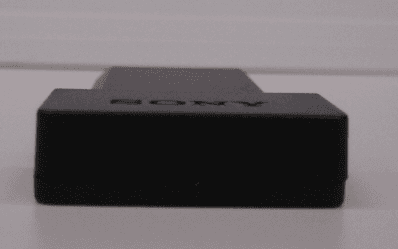
Click to zoom
Application Details
- Equipment Class
- DTS - Digital Transmission System
- Date of Grant
- Nov 29, 2010
- Application Purpose
- Original Equipment
- Date of Application
- Nov 29, 2010
- Equipment Note
- Wireless transceiver
- Frequency Range
- 5736.00000000 - 5814.00000000
- Company
- Sony Group Corporation
- Country
- Japan
Documents & Files
Document Text
Text extracted from the exhibit documents filed with the FCC. Open a document above to read the original.
Users Manual
filename[E:\BDV2011\Models\E2WF- E8WF_UC\4261379111\4261379111BDV780WUC\Cover\01cov-cel.fm] masterpage:Right model name [BDV-E780W/BDV-E980W] [4-261-379-11(1)] BDV-E780W/BDV-E980W 4-261-379-11(1) Blu-ray Disc/DVD Home Theatre System Operating Instructions gb_book.book Page 1 Thursday, November 25, 2010 6:04 PM masterpage:Left specdef v20070110 filename[E:\BDV2011\Models\E2WF- E8WF_UC\4261379111\4261379111BDV780WUC\gb02saf.fm] model name [BDV-E780W/BDV-E980W] [4-261-379-11(1)] 2 US Do not install the appliance in a confined space, such as a bookcase or built-in cabinet. To reduce the risk of fire, do not cover the ventilation opening of the apparatus with newspapers, tablecloths, curtains, etc. Do not place the naked flame sources such as lighted candles on the apparatus. Do not expose batteries or apparatus with battery-installed to excessive heat such as sunshine, fire or the like. To prevent injury, this apparatus must be securely attached to the floor/wall in accordance with the installation instructions. Indoor use only. CAUTION The use of optical instruments with this product will increase eye hazard. As the laser beam used in this Blu-ray Disc / DVD Home Theatre System is harmful to eyes, do not attempt to disassemble the cabinet. Refer servicing to qualified personnel only. This appliance is classified as a CLASS 3R LASER product. Visible and invisible laser radiation is emitted when the laser protective housing is opened, so be sure to avoid direct eye exposure. This marking is located on the laser protective housing inside the enclosure. This appliance is classified as a CLASS 1 LASER product. This marking is located on the rear exterior. For the customers in the U.S.A. To reduce the risk of fire or electric shock, do not expose this apparatus to rain or moisture. These following indications are located on the rear exterior. This symbol is intended to alert the user to the presence of uninsulated “dangerous voltage” within the product’s enclosure that may be of sufficient magnitude to constitute a risk of electric shock to persons. This symbol is intended to alert the user to the presence of important operating and maintenance (servicing) instructions in the literature accompanying the appliance. Owner’s Record The model and serial numbers are located on the bottom exterior of the unit. Record these numbers in the space provided below. Refer to them whenever you call upon your Sony dealer regarding this product. Model No. BDV-E780W Serial No.______________ The following FCC statement applies only to the version of this model manufactured for sale in the U.S.A. Other versions may not comply with FCC technical regulations. NOTE: This equipment has been tested and found to comply with the limits for a Class B digital device, pursuant to Part 15 of the FCC Rules. These limits are designed to provide reasonable protection against harmful interference in a residential installation. This equipment generates, uses, and can radiate radio frequency energy and, if not installed and used in accordance with the instructions, may cause harmful interference to radio communications. However, there is no guarantee that interference will not occur in a particular installation. If this equipment does cause harmful interference to radio or television reception, which can be determined by turning the equipment off and on, the user is encouraged to try to correct the interference by one or more of the following measures: – Reorient or relocate the receiving antenna (aerial). – Increase the separation between the equipment and receiver. – Connect the equipment into an outlet on a circuit different from that to which the receiver is connected. – Consult the dealer or an experienced radio/TV technician for help. CAUTION You are cautioned that any changes or modifications not expressly approved in this manual could void your authority to operate this equipment. Properly shielded and grounded cables and connectors must be used for connection to host computers and/or peripherals in order to meet FCC emission limits. WARNING gb_book.book Page 2 Thursday, November 25, 2010 6:04 PM masterpage:Right specdef v20070110 filename[E:\BDV2011\Models\E2WF- E8WF_UC\4261379111\4261379111BDV780WUC\gb02saf.fm] model name [BDV-E780W/BDV-E980W] [4-261-379-11(1)] 3 US Important Safety Instructions 1) Read these instructions. 2) Keep these instructions. 3) Heed all warnings. 4) Follow all instructions. 5) Do not use this apparatus near water. 6) Clean only with dry cloth. 7) Do not block any ventilation openings. Install in accordance with the manufacturer’s instructions. 8) Do not install near any heat sources such as radiators, heat registers, stoves, or other apparatus (including amplifiers) that produce heat. 9) Do not defeat the safety purpose of the polarized or grounding-type plug. A polarized plug has two blades with one wider than the other. A grounding type plug has two blades and a third grounding prong. The wide blade or the third prong are provided for your safety. If the provided plug does not fit into your outlet, consult an electrician for replacement of the obsolete outlet. 10) Protect the power cord from being walked on or pinched particularly at plugs, convenience receptacles, and the point where they exit from the apparatus. 11) Only use attachments/ accessories specified by the manufacturer. 12) Use only with the cart, stand, tripod, bracket, or table specified by the manufacturer, or sold with the apparatus. When a cart is used, use caution when moving the cart/ apparatus combination to avoid injury from tip-over. 13) Unplug this apparatus during lightning storms or when unused for long periods of time. 14) Refer all servicing to qualified service personnel. Servicing is required when the apparatus has been damaged in any way, such as power-supply cord or plug is damaged, liquid has been spilled or objects have fallen into the apparatus, the apparatus has been exposed to rain or moisture, does not opera…
Text truncated - open the document above for the full version.
Users Manual
Sound Adjustment masterpage:Right specdef v20070110 filename[E:\BDV2011\Models\E2WF- E8WF_UC\4261379111\4261379111BDV780WUC\gb06sou.fm] model name [BDV-E780W/BDV-E980W] [4-261-379-11(1)] 43 US Selecting the Effect to Suit the Source You can select a suitable sound mode for movies or music. Press SOUND MODE repeatedly during playback until the desired mode appears in the front panel display. •“AUTO”: The system selects “MOVIE” or “MUSIC” automatically to produce the sound effect depending on the disc or sound stream. • “MOVIE”: The system provides the sound for movies. • “MUSIC”: The system provides the sound for music. • “SPORTS”: The system adds reverberation for sports programs. • “GAME ROCK”: The system provides the sound for music/rhythm games. • “OMNI-DIR”: The same sound is audible anywhere in the room. • “3D SUR.”: “3D SUR.” is a unique Sony algorithm used for playing 3D (three- dimensional) content that provides a 3D sound experience with depth and presence by creating a virtual sound field close to your ears. • “HALL”: The system reproduces the sound of a concert hall. • “NIGHT”: You can enjoy sound effects or dialog, as you would in a movie theater, even at low volume. It is useful for watching movies at night. • Depending on the disc or source, when you select “AUTO,” the beginning of the sound may be cut off as the system selects the optimum mode automatically. To avoid cutting the sound, select other than “AUTO.” • Depending on the input stream, the sound mode may not be effective. • When you play a Super Audio CD, this function does not work. • When “NIGHT” is selected and sound is output from the center speaker, this effect is more pronounced, as speech (movie dialog, etc.) is easy to hear. When sound is not output from the center speaker, the system optimally adjusts the volume. Selecting the Audio Format, Multilingual Tracks, or Channel When the system is playing a BD/DVD VIDEO recorded in multiple audio formats (PCM, Dolby Digital, MPEG audio, or DTS) or multilingual tracks, you can change the audio format or language. With a CD, you can select the sound from the right or left channel and listen to the sound of the selected channel through both the right and left speakers. Press AUDIO repeatedly during playback to select the desired audio signal. The audio information appears on the TV screen. Sound Adjustment 8 0 97 564 231 SOUND MODE AUDIO gb_book.book Page 43 Thursday, November 25, 2010 6:04 PM masterpage:Left specdef v20070110 filename[E:\BDV2011\Models\E2WF- E8WF_UC\4261379111\4261379111BDV780WUC\gb06sou.fm] model name [BDV-E780W/BDV-E980W] [4-261-379-11(1)] 44 US xBD/DVD VIDEO Depending on the BD/DVD VIDEO, the choice of language varies. When 4 digits are displayed, they indicate a language code. See “Language Code List” (page 79) to confirm which language the code represents. When the same language is displayed two or more times, the BD/DVD VIDEO is recorded in multiple audio formats. xDVD-VR The types of sound tracks recorded on a disc are displayed. Example: •[ Stereo] • [ Stereo (Audio1)] • [ Stereo (Audio2)] •[ Main] •[ Sub] • [ Main/Sub] • [ Stereo (Audio1)] and [ Stereo (Audio2)] do not appear when only one audio stream is recorded on the disc. xCD •[ Stereo]: The standard stereo sound. • [ 1/L]: The sound of the left channel (monaural). • [ 2/R]: The sound of the right channel (monaural). • [ L+R]: The sound of both the left and right channels output from each individual speaker. Enjoying Multiplex Broadcast Sound (DUAL MONO) You can enjoy multiplex broadcast sound when the system receives or plays a Dolby Digital multiplex broadcast signal. • To receive the Dolby Digital signal, you need to connect a TV or other component to the unit with a digital coaxial or optical cord (pages 22, 24). If your TV is compatible with the Audio Return Channel function (pages 22,64), you can receive a Dolby Digital signal via an HDMI cable. Press AUDIO repeatedly until the desired signal appears in the front panel display. •“MAIN”: Sound of the main language will be output. • “SUB”: Sound of the sub language will be output. • “MAIN/SUB”: Mixed sound of both the main and sub languages will be output. AUDIO gb_book.book Page 44 Thursday, November 25, 2010 6:04 PM Tun e r masterpage:Right specdef v20070110 filename[E:\BDV2011\Models\E2WF- E8WF_UC\4261379111\4261379111BDV780WUC\gb07rad.fm] model name [BDV-E780W/BDV-E980W] [4-261-379-11(1)] 45 US Listening to the Radio You can enjoy radio sound with the system’s speakers. 1Press FUNCTION repeatedly until “FM” appears in the front panel display. 2Select the radio station. Automatic tuning Press and hold TUNING +/– until the auto scanning starts. [Auto Tuning] appears on the TV screen. Scanning stops when the system tunes in a station. To stop the automatic tuning manually, press TUNING +/– or x. Manual tuning Press TUNING +/– repeatedly. 3Adjust the volume by pressing VOL +/–. If an FM program is noisy If an FM program is noisy, you can select monaural reception. There will be no stereo effect, but reception will improve. 1Press OPTIONS. The option menu appears on the TV screen. 2Press X/x to select [FM Mode], then press . 3Press X/x to select [Monaural]. • [Stereo]: Stereo reception. • [Monaural]: Monaural reception. 4Press . The setting is made. To turn off the radio Press "/1. You can preset up to 20 stations. Before tuning, make sure to turn down the volume to minimum. 1Press FUNCTION repeatedly until “FM” appears in the front panel display. 2Press and hold TUNING +/– until the auto scanning starts. Scanning stops when the system tunes in a station. 3Press OPTIONS. The option menu appears on the TV screen. 4Press X/x to select [Preset Memory], then press . 5Press X/x to select the preset number you want, then press . 6Repeat Steps 2 to 5 to store other stations. To change the preset number Select the desired preset number by pressing PRESET +/–, then perform the procedure from Step 3. Tuner 8 0 97 564 231 x PRESET +/– VOL +/–…
Text truncated - open the document above for the full version.
External Photos
Appearance
ID Label/Location Info
ISSUED 234 A B C D E F A B C D E F SCALE (E) (J) UNIT ANGLE SHEET 6 1 2 3 4 5 TOLERANCE FAMILY RANK X X X X X X HISTORY X COUNT SUFFIX REPL. REVISIONSIGN. DRAWN BYPLANNED BYCHECKED BYAPPROVED BY TENTATIVE MODEL PART NO. PART NO. MATERIAL(COLOR)FINISH(COLOR) ORIGINAL MODEL USED 0N mm TITLE/DESCRIPTION SONY STANDARD DRAWING F spec - D42 '09.4 A4 1 1 DATE ECN-NO. THIS PART SHOULD NOT CONTAIN ANY SUBSTANCES WHICH ARE SPECIFIED IN SS-00259-01. PURCHASE RECYCLED RESINS AND WIRE RODS ONLY FROM THE BUSINESS PARTNERS THAT SONY APPROVES AS GREEN PARTNERS. 1 CONFIDENTIAL THIS DOCUMENT IS THE PROPRIETARY PROPERTY OF SONY. ITS USE IS AUTHORIZED ONLY FOR RESPONDING TO A REQUEST FOR QUOTATION,OR FOR THE PERFORMANCE OF WORK FOR SONY. ALL QUESTIONS MUST BE REFERRED TO IS PROHIBITED. OFFENDERS WILL BE HELD LIABLE FOR THE PAYMENT OF DAMAGES. ALL RIGHTS RESERVED IN THE EVENT OF THE GRANT OF A PATENT, UTILITY MODEL OR DESIGN.COPYRIGHT RESERVED. THE LOCAL PURCHASING DEPARTMENT OF SONY. THE REPRODUCTION, DISTRIBUTION AND UTILIZATION OF THIS DOCUMENT AS WELL AS THE COMMUNICATION OF ITS CONTENTS TO OTHERS WITHOUT EXPRESS AUTHORIZATION 30 51.5 2:1 Pro/E -- -- -- ATOM - -
Internal Photos
Inside Side-A (with Shieled-can) Side-A (without Shieled-can) Side-B
RF Exposure Info
UL Japan, Inc. Head Office EMC Lab. 4383-326 Asama-cho, Ise-shi, Mie-ken 516-0021 JAPAN Telephone : +81 596 24 8116 Facsimile : +81 596 24 8124 Applicant: Sony EMCS Corporation Kisarazu TEC Type of Equipment: Wireless transceiver Model No. : EZW-RT50 FCC ID: AK8148935911 IC Number:409B-148935911 Sony EMCS Corporation Kisarazu TEC declares that Model : EZW-RT50 complies with FCC radiation exposure requirement specified in the FCC Rules 2.1091 (for mobile). The “EZW-RT50“ has 34.67 mW of conducted Peak Output power and 33.11 mW of EIRP. This kind of equipment is below 60/frequency[GHz] mW(TCB Exclusion List) so that SAR testing is excluded. The Following calculation is the reference data for 20cm distance. RF Exposure Calculations: The following information provides the minimum separation distance for the highest gain antenna provided with the “EZW-RT50“ as calculate d from FCC OET Bulletin 65 Appendix A, Table (B) Limits for General Population / Uncontrolled Exposure. This calculation is based on the highest EIRP possible from the system, considering maximum power and antenna gain, and considering a 1.0mW/cm^2 uncontrolled exposure limit. The Friis formula used was: S = (P * G) / (4* π * r 2 ) Where P = 34.67 mW (Maximum peak output power) G = 0.95 Numerical Antenna gain; equal to-0.20dBi r =20.0 cm For: EZW-RT50S =0.00659 mW/cm 2 No. : 31BE0147-HO-01 RF Exposure / MPE Calculation
Test Report
Test report No. : 31BE0147-HO-01-A-R2 Page : 16 of 41 Issued date : October 19, 2010 Revised date : November 26, 2010 FCC ID : AK8148935911 UL Japan, Inc. Head Office EMC Lab. 4383-326 Asama-cho, Ise-shi, Mie-ken 516-0021 JAPAN Telephone : +81 596 24 8116 Facsimile : +81 596 24 8124 APPENDIX 2: Data of EMI test Conducted Emission DATA OF CONDUCTED EMISSION TEST UL Japan, Inc. Head Office EMC Lab. No.4 Semi Anechoic Chamber Date : 2010/09/25 Company : Sony Corporaion Report No. : 31BE0147-HO-01 Kind of EUT : Power : AC 120V / 60Hz Model No. : EZW-RT50 Temp./Humi. : 23deg.C / 66% Serial No. : - Engineer : Tomotaka Sasagawa Mode / Remarks : Tx 5736MHz LIMIT : FCC15.207 QP FCC15.207 AV CHART:WITH FACTOR,Peak hold data. CALCULATION:RESULT[dBuV]=READING[dBuV]+C.F[dB](LISN LOSS+CABLE LOSS) Except for the above table : adequate margin data below the limits. Frequency[Hz] [dBuV]<< QP/AV DATA >> L:QP:AV N:QP:AV .15M30M.2M.3M.5M.7M1M2M3M5M7M10M20M 0 10 20 30 40 50 60 70 80 Frequency Reading LevelReading LevelCorr.ResultsResultsLimitLimitMarginMargin PhaseComment Frequency QPAVFactorQPAVQPAVQPAVPhaseComment [MHz][dBuV][dBuV][dB][dBuV][dBuV][dBuV][dBuV][dB][dB] PhaseComment 0.1587025.114.113.238.327.365.555.527.228.2N 0.2036534.923.013.348.236.363.553.515.317.2N 0.5618017.14.513.330.417.856.046.025.628.2N 6.6789913.43.213.727.116.960.050.032.933.1N 11.6208412.92.914.127.017.060.050.033.033.0N 27.6608824.523.815.039.538.860.050.020.511.2N 0.1587023.914.313.237.127.565.555.528.428.0L 0.2036535.222.813.348.536.163.553.515.017.4L 0.5618017.84.113.331.117.456.046.024.928.6L 6.6789913.53.813.727.217.560.050.032.832.5L 11.5874212.83.114.126.917.260.050.033.132.8L 27.6608824.524.015.039.539.060.050.020.511.0L Test report No. : 31BE0147-HO-01-A-R2 Page : 17 of 41 Issued date : October 19, 2010 Revised date : November 26, 2010 FCC ID : AK8148935911 UL Japan, Inc. Head Office EMC Lab. 4383-326 Asama-cho, Ise-shi, Mie-ken 516-0021 JAPAN Telephone : +81 596 24 8116 Facsimile : +81 596 24 8124 Conducted Emission Test place Head Office EMC Lab. No.4 Semi Anechoic Chamber Report No. 31BE0147-HO-01 Date 09/24/2010 Temperature/ Humidity 23 deg.C./ 66% Engineer Tomotaka Sasagawa Mode Tx 5736MHz 5762MHz 5814MHz Y scale [dBuV] Chart N L Test report No. : 31BE0147-HO-01-A-R2 Page : 18 of 41 Issued date : October 19, 2010 Revised date : November 26, 2010 FCC ID : AK8148935911 UL Japan, Inc. Head Office EMC Lab. 4383-326 Asama-cho, Ise-shi, Mie-ken 516-0021 JAPAN Telephone : +81 596 24 8116 Facsimile : +81 596 24 8124 Conducted Emission DATA OF CONDUCTED EMISSION TEST UL Japan, Inc. Head Office EMC Lab. No.4 Semi Anechoic Chamber Date : 2010/09/25 Company : Sony Corporaion Report No. : 31BE0147-HO-01 Kind of EUT : Power : AC 120V / 60Hz Model No. : EZW-RT50 Temp./Humi. : 23deg.C / 66% Serial No. : - Engineer : Tomotaka Sasagawa Mode / Remarks : Rx 5762MHz LIMIT : FCC15.207 QP FCC15.207 AV CHART:WITH FACTOR,Peak hold data. CALCULATION:RESULT[dBuV]=READING[dBuV]+C.F[dB](LISN LOSS+CABLE LOSS) Except for the above table : adequate margin data below the limits. Frequency[Hz] [dBuV]<< QP/AV DATA >> L:QP:AV N:QP:AV .15M30M.2M.3M.5M.7M1M2M3M5M7M10M20M 0 10 20 30 40 50 60 70 80 Frequency Reading LevelReading LevelCorr.ResultsResultsLimitLimitMarginMargin PhaseComment Frequency QPAVFactorQPAVQPAVQPAVPhaseComment [MHz][dBuV][dBuV][dB][dBuV][dBuV][dBuV][dBuV][dB][dB] PhaseComment 0.1552124.913.913.238.127.165.755.727.628.6N 0.2031035.123.813.348.437.163.553.515.116.4N 0.5614216.94.313.330.217.656.046.025.828.4N 6.6664213.23.613.726.917.360.050.033.132.7N 11.2313012.42.914.126.517.060.050.033.533.0N 27.8321323.723.115.038.738.160.050.021.311.9N 0.1572525.814.213.239.027.465.655.626.628.2L 0.2036535.224.313.348.537.663.553.515.015.9L 0.5676017.24.513.330.517.856.046.025.528.2L 6.6638813.43.913.727.117.660.050.032.932.4L 11.3535012.32.814.126.416.960.050.033.633.1L 27.6608824.324.115.039.339.160.050.020.710.9L Test report No. : 31BE0147-HO-01-A-R2 Page : 19 of 41 Issued date : October 19, 2010 Revised date : November 26, 2010 FCC ID : AK8148935911 UL Japan, Inc. Head Office EMC Lab. 4383-326 Asama-cho, Ise-shi, Mie-ken 516-0021 JAPAN Telephone : +81 596 24 8116 Facsimile : +81 596 24 8124 6dB Bandwidth Test place Head Office EMC Lab. No.11 Measurement Room Report No. 31BE0147-HO-01 Date 09/20/2010 Temperature/ Humidity 22 deg.C./ 55% Engineer Hiroshi Kukita Mode Tx Frequency 6dB Bandwidth Limit [MHz] [MHz] [kHz] 5736 9.216 >500 5762 8.500 >500 5814 10.026 >500 Test report No. : 31BE0147-HO-01-A-R2 Page : 20 of 41 Issued date : October 19, 2010 Revised date : November 26, 2010 FCC ID : AK8148935911 UL Japan, Inc. Head Office EMC Lab. 4383-326 Asama-cho, Ise-shi, Mie-ken 516-0021 JAPAN Telephone : +81 596 24 8116 Facsimile : +81 596 24 8124 6dB Bandwidth Tx 5736MHz 5762MHz 5814MHz Test report No. : 31BE0147-HO-01-A-R2 Page : 21 of 41 Issued date : October 19, 2010 Revised date : November 26, 2010 FCC ID : AK8148935911 UL Japan, Inc. Head Office EMC Lab. 4383-326 Asama-cho, Ise-shi, Mie-ken 516-0021 JAPAN Telephone : +81 596 24 8116 Facsimile : +81 596 24 8124 Maximum Peak Output Power Test place Head Office EMC Lab. No.11 Measurement Room Report No. 31BE0147-HO-01 Date 09/20/2010 Temperature/ Humidity 22 deg.C./ 55% Engineer Hiroshi Kukita Mode Tx Antenna A Freq.ReadingCableAtten.Margin Loss [MHz][dBm][dB][dB][dBm][mW][dBm][mW][dB] 57362.312.8710.0415.2233.2730.00100014.78 57622.492.8710.0415.4034.6730.00100014.60 58142.852.8710.0515.7737.7630.00100014.23 Antenna B Freq.ReadingCableAtten.Margin Loss [MHz][dBm][dB][dB][dBm][mW][dBm][mW][dB] 57362.322.8710.0415.2333.3430.00100014.77 57622.652.8710.0415.5635.9730.00100014.44 58143.632.8710.0516.5545.1930.00100013.45 Sample Calculation: Result = Reading + Cable Loss (including the cable(s) customer supplied) + Attenuator ResultLimit ResultLimit Test report No. : 31BE0147-HO-01-A-R2 Page : 22 of 41 Issued date : October 19, 2010 Revised date : November 26, 2010 FCC ID : AK8148935911 UL Japan, In…
Text truncated - open the document above for the full version.
Test Report
Test report No. : 31BE0147-HO-01-A-R2 Page : 1 of 41 Issued date : October 19, 2010 Revised date : November 26, 2010 FCC ID : AK8148935911 UL Japan, Inc. Head Office EMC Lab. 4383-326 Asama-cho, Ise-shi, Mie-ken 516-0021 JAPAN Telephone : +81 596 24 8116 Facsimile : +81 596 24 8124 RADIO TEST REPORT Test Report No. : 31BE0147-HO-01-A-R2 Applicant : Sony EMCS Corporation Kisarazu TEC Type of Equipment : Wireless transceiver Model No. : EZW-RT50 FCC ID : AK8148935911 Test regulation: FCC Part 15 Subpart C 2010 Test Result : Complied 1. This test report shall not be reproduced in full or partial, without the written approval of UL Japan, Inc. 2. The results in this report apply only to the sample tested. 3. This sample tested is in compliance with the above regulation. 4. The test results in this report are traceable to the national or international standards. 5. This test report must not be used by the customer to claim product certification, approval, or endorsement by NVLAP, NIST, or any agency of the Federal Government. 6. This report is a revised version of 31BE0147-HO-01-A-R1. 31BE0147-HO-01-A-R1 is replaced with this report. Date of test: _____________________________ Representative test engineer: _____________________________ Tomotaka Sasagawa Engineer of EMC Service Approved by: _____________________________ Mitsuru Fujimura Manager of EMC Service MF058b (15.09.10) NVLAP LAB CODE: 200572-0 This laboratory is accredited by the NVLAP LAB CODE 200572-0, U.S.A. The tests reported herein have been performed in accordance with its terms of accreditation. *As for the range of Accreditation in NVLAP, you may refer to the WEB address, http://www.ul.com/japan/jpn/pages/services/emc/about/ma rk1/index.jsp#nvlap September 20 to 24, 2010 Test report No. : 31BE0147-HO-01-A-R2 Page : 2 of 41 Issued date : October 19, 2010 Revised date : November 26, 2010 FCC ID : AK8148935911 UL Japan, Inc. Head Office EMC Lab. 4383-326 Asama-cho, Ise-shi, Mie-ken 516-0021 JAPAN Telephone : +81 596 24 8116 Facsimile : +81 596 24 8124 CONTENTS PAGE SECTION 1: Customer information ......................................................................................................... 3 SECTION 2: Equipment under test (E.U.T.) ........................................................................................... 3 SECTION 3: Test specification, procedures & results ............................................................................ 4 SECTION 4: Operation of E.U.T. during testing .................................................................................... 7 SECTION 5: Conducted Emission ............................................................................................................ 9 SECTION 6: Spurious Emission ............................................................................................................. 10 SECTION 7: Antenna Terminal Conducted Tests ................................................................................ 12 APPENDIX 1: Photographs of test setup ............................................................................................... 13 Conducted Emission ......................................................................................................................... 13 Radiated Spurious Emission ............................................................................................................. 14 Worst Case Position (Horizontal: X-axis/ Vertical:Z-axis) .............................................................. 15 APPENDIX 2: Data of EMI test .............................................................................................................. 16 Conducted Emission ......................................................................................................................... 16 6dB Bandwidth ................................................................................................................................. 19 Maximum Peak Output Power .......................................................................................................... 21 Radiated Spurious Emission ............................................................................................................. 22 The tested burst timing ...................................................................................................................... 29 Conducted Spurious Emission .......................................................................................................... 30 Conducted Emission Band Edge compliance ................................................................................... 37 Power Density ................................................................................................................................... 38 99% Occupied Bandwidth................................................................................................................. 40 APPENDIX 3: Test instruments ............................................................................................................. 41 Test report No. : 31BE0147-HO-01-A-R2 Page : 3 of 41 Issued date : October 19, 2010 Revised date : November 26, 2010 FCC ID : AK8148935911 UL Japan, Inc. Head Office EMC Lab. 4383-326 Asama-cho, Ise-shi, Mie-ken 516-0021 JAPAN Telephone : +81 596 24 8116 Facsimile : +81 596 24 8124 SECTION 1: Customer information Company Name : Sony EMCS Corporation Kisarazu TEC Brand or Trade name : SONY Address : 8-4 Shiomi, Kisarazu-shi, Chiba 292-0834 Japan Telephone Number : +81-438-37-3982 Facsimile Number : +81-438-37-4705 Contact Person : Kazuhiko Nagano SECTION 2: Equipment under test (E.U.T.) 2.1 Identification of E.U.T. Type of Equipment : Wireless transceiver Model No. : EZW-RT50 Serial No. : Refer to Section 4, Clause 4.2 Rating : DC 3.3V Receipt Date of Sample : September 16, 2010 Country of Mass-production : Malaysia Condition of EUT : Engineering prototype (Not for Sale: This sample i…
Text truncated - open the document above for the full version.
Test Setup Photos
Test report No. : 31BE0147-HO-01-A-R2 Page : 13 of 41 Issued date : October 19, 2010 Revised date : November 26, 2010 FCC ID : AK8148935911 UL Japan, Inc. Head Office EMC Lab. 4383-326 Asama-cho, Ise-shi, Mie-ken 516-0021 JAPAN Telephone : +81 596 24 8116 Facsimile : +81 596 24 8124 APPENDIX 1: Photographs of test setup Conducted Emission Photo 1 Photo 2 Test report No. : 31BE0147-HO-01-A-R2 Page : 14 of 41 Issued date : October 19, 2010 Revised date : November 26, 2010 FCC ID : AK8148935911 UL Japan, Inc. Head Office EMC Lab. 4383-326 Asama-cho, Ise-shi, Mie-ken 516-0021 JAPAN Telephone : +81 596 24 8116 Facsimile : +81 596 24 8124 Radiated Spurious Emission Photo 1 Photo 2 Test report No. : 31BE0147-HO-01-A-R2 Page : 15 of 41 Issued date : October 19, 2010 Revised date : November 26, 2010 FCC ID : AK8148935911 UL Japan, Inc. Head Office EMC Lab. 4383-326 Asama-cho, Ise-shi, Mie-ken 516-0021 JAPAN Telephone : +81 596 24 8116 Facsimile : +81 596 24 8124 Worst Case Position (Horizontal: X-axis/ Vertical:Z-axis) X-axis Y-axis Z-axis
Contact Information
Applicant
Kazuyuki Hori(Chief EMC/RF Compliance Specialist)
Technical Contact
UL Japan, Inc.Mitsuru Fujimura
[email protected]81-596-24-8116
4383-326 Asama-cho, Ise-shi, · Mie-ken · Japan
Test Firm
UL Japan, Inc. Head office EMC Lab.Tetsuya Hashimoto
Technical Specifications
| # | Rule Parts | Frequency Range | Power Output |
|---|---|---|---|
| 1 | 15C | 5.74 GHz - 5.81 GHz | 45.19 mW |
Other Applications from Sony Group Corporation
AK8WW81782
Aug 21, 2026Radio Equipment
Equipment Class
DSS - Part 15 Spread Spectrum TransmitterAK8CFIZCP2
Aug 03, 2026Wireless Controller
Equipment Class
DSS - Part 15 Spread Spectrum TransmitterAK8OEV321MUH
Apr 14, 2026LCD Monitor
Equipment Class
JAD - Part 15 Class A Digital DeviceAK8OEV431MUH
Apr 14, 2026LCD Monitor
Equipment Class
JAD - Part 15 Class A Digital DeviceAK8OEV271MUH
Apr 14, 2026LCD Monitor
Equipment Class
JAD - Part 15 Class A Digital Device