AK8BM1510Bluetooth Module
Sony Group Corporation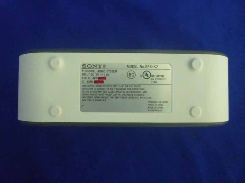
Click to zoom
Application Details
- Equipment Class
- DSS - Part 15 Spread Spectrum Transmitter
- Date of Grant
- Aug 23, 2015
- Application Purpose
- Original Equipment
- Date of Application
- Aug 20, 2015
- Equipment Note
- Bluetooth Module
- Frequency Range
- 2402.00000000 - 2480.00000000
- Company
- Sony Group Corporation
- Country
- Japan
Documents & Files
Document Text
Text extracted from the exhibit documents filed with the FCC. Open a document above to read the original.
Users Manual
Installation manual 1. Mount parts on PCB (including main board & jack PCB) Main board: top side Main board: bottom side For a module with print circuit board antenna, to eliminate the influence from other components or ground, a clearance area around the print circuit board antenna is necessary, please refer to following picture. In this area, there should be no metal in it. Besides x-y-axis, there should also be no metal at the Z-axis direction. Jack PCB 2. According to the exploded view (refer to final page) to make a complete product. 2a: solder the speaker wire rightly, then install the main board to the PCB holder with screws. 2b: Install the battery pack / NFC module / jack PCB to cabinet rightly. 2c: Install the main board with speakers. Then connect battery pack / jack PCB / NFC module / microphone. 2d: Install the speaker holder with screws, then install the speaker grill. 2e: Stick the name plate and date code/serial number on bottom side. The END host which install this module should bear the label which display “ contains FCC ID: AK8BM1510 and contient IC : 409B‐BM1510"
External Photos
R AUDIX Technology (Shenzhen) Co., Ltd. FCC ID:AK8BM1510 page 15-1 Audix Technology (Shenzhen) Co., Ltd. Report No. ACS-F15210 15. PHOTOGRAPH OF EUT Figure 1 General Appearance of the EUT Figure 2 General Appearance of the EUT
External Photos
R AUDIX Technology (Shenzhen) Co., Ltd. IC:409B-BM1510 page 15-1 Audix Technology (Shenzhen) Co., Ltd. Report No. ACS-I15082 15. PHOTOGRAPH OF EUT Figure 1 Front Side of PCB Board Figure 2 Back Side of PCB Board
ID Label/Location Info
New label for BT module: This module label will be printed on PCB beside the BT module directly, distance is about 5mm. Showed as following. 效果如下面现有的PCB的照片,不会不清晰。 Location
Internal Photos
R AUDIX Technology (Shenzhen) Co., Ltd. IC:409B-BM1510 page 15-2 Audix Technology (Shenzhen) Co., Ltd. Report No. ACS-I15082 Figure 3 Front side of the Module Figure 4 Back side of the Module
Internal Photos
R AUDIX Technology (Shenzhen) Co., Ltd. FCC ID:AK8BM1510 page 15-2 Audix Technology (Shenzhen) Co., Ltd. Report No. ACS-F15210 Figure 3 Inside of the EUT Figure 4 Inside of the EUT R AUDIX Technology (Shenzhen) Co., Ltd. FCC ID:AK8BM1510 page 15-3 Audix Technology (Shenzhen) Co., Ltd. Report No. ACS-F15210 Figure 5 Inside of the EUT Figure 6 Inside of the EUT R AUDIX Technology (Shenzhen) Co., Ltd. FCC ID:AK8BM1510 page 15-4 Audix Technology (Shenzhen) Co., Ltd. Report No. ACS-F15210 Figure 7 Inside of the EUT Figure 8 Adaptor #1 R AUDIX Technology (Shenzhen) Co., Ltd. FCC ID:AK8BM1510 page 15-5 Audix Technology (Shenzhen) Co., Ltd. Report No. ACS-F15210 Figure 9 Adaptor #1 Figure 10 Adaptor #2 R AUDIX Technology (Shenzhen) Co., Ltd. FCC ID:AK8BM1510 page 15-6 Audix Technology (Shenzhen) Co., Ltd. Report No. ACS-F15210 Figure 11 Adaptor #2
RF Exposure Info
Product NameBluetooth Module Model Number: BM1510 FCCID: AK8BM1510 RADIO FRREQUENCY EXPOSURE COMPLIANCE RESULT : Test Standard : FCC KDB Publication 447498 D01 V05R02 Clause 4.3.1, The 1‐g and 10‐g SAR test exclusion thresholds for 100 MHz to 6 GHz at test separation distances 50 mm are determined by: [(max. power of channel, including tune‐up tolerance, mW)/(min. test separation distance, mm)] ∙ [f (GHz) ] 3.0 for 1‐g SAR and 7.5 for 10‐g extremity SAR, where • f (GHz) is the RF channel transmit frequency in GHz • Power and distance are rounded to the nearest mW and mm before calculation • The result is rounded to one decimal place for comparison • 3.0 and 7.5 are referred to as the numeric thresholds in the step 2 below The test exclusions are applicable only when the minimum test separation distance is 50 mm and for transmission frequencies between 100 MHz and 6 GHz. When the minimum test separation distance is < 5 mm, a distance of 5 mm according to 5) in section 4.1 is applied to determine SAR test exclusion. According to the actual measurement, max. power of channel, including tune‐up tolerance =0.00030mW min. test separation distance= 5mm f (GHz) =1.55 The test result is 0.000933.0 for 1‐g SAR 7.5 for 10‐g SAR, hence the EUT is excluded from SAR evaluation according to FCC KDB Publication 447498 D01: General RF Exposure Guidance V05.
Test Report
R AUDIX Technology (Shenzhen) Co., Ltd. FCC ID:AK8BM1510 Audix Technology (Shenzhen) Co., Ltd. Report No. ACS-F15210 FCC PART 15C TEST REPORT FOR CERTIFICATION On Behalf of Sony Corporation Bluetooth Module Model No.: BM1510 FCC ID: AK8BM1510 Prepared for : Sony Corporation 1-7-1 Konan, Minato-ku, Tokyo 108-0075 Japan Prepared By : Audix Technology (Shenzhen) Co., Ltd. No. 6, Ke Feng Rd., 52 Block, Shenzhen Science & Industrial Park, Nantou, Shenzhen, Guangdong, China Tel: (0755) 26639496 Report Number ACS-F15210 Date of Test Jul.08~15, 2015 Date of Report Aug.11, 2015 R AUDIX Technology (Shenzhen) Co., Ltd. FCC ID:AK8BM1510 Audix Technology (Shenzhen) Co., Ltd. Report No. ACS-F15210 TABLE OF CONTENTS Description Page 1. SUMMARY OF STANDARDS AND RESULTS .......................................................... 1-1 1.1. Description of Standards and Results .................................................................................. 1-1 2. GENERAL INFORMATION ......................................................................................... 2-1 2.1. Description of Device (EUT) ............................................................................................... 2-1 2.2. Tested Supporting System Details ....................................................................................... 2-2 2.3. Block Diagram of connection between EUT and simulators ............................................... 2-2 2.4. Test information ................................................................................................................... 2-2 2.5. Test Facility ......................................................................................................................... 2-3 2.6. Measurement Uncertainty (95% confidence levels, k=2) .................................................... 2-3 3. POWER LINE CONDUCTED EMISSION TEST ....................................................... 3-1 3.1. Test Equipments ................................................................................................................... 3-1 3.2. Block Diagram of Test Setup ............................................................................................... 3-1 3.3. Power Line Conducted Emission Test Limits ...................................................................... 3-1 3.4. Configuration of EUT on Test ............................................................................................. 3-2 3.5. Operating Condition of EUT ............................................................................................... 3-2 3.6. Test Procedure ..................................................................................................................... 3-2 3.7. Power Line Conducted Emission Test Results .................................................................... 3-2 4. RADIATED EMISSION MEASUREMENT ................................................................. 4-1 4.1. Test Equipment .................................................................................................................... 4-1 4.2. Block Diagram of Test Setup ............................................................................................... 4-1 4.3. Radiated Emission Limit Standard: ..................................................................................... 4-2 4.4. EUT Configuration on Test ................................................................................................. 4-2 4.5. Operating Condition of EUT ............................................................................................... 4-2 4.6. Test Procedure ..................................................................................................................... 4-2 4.7. Radiated Emission Test Results ........................................................................................... 4-3 5. CONDUCTED SPURIOUS EMISSIONS ...................................................................... 5-1 5.1. Test Equipment .................................................................................................................... 5-1 5.2. Limit ..................................................................................................................................... 5-1 5.3. Test Procedure ..................................................................................................................... 5-1 5.4. Test result ............................................................................................................................. 5-1 6. 20 DB BANDWIDTH TEST ........................................................................................... 6-1 6.1. Test Equipment .................................................................................................................... 6-1 6.2. Limit ..................................................................................................................................... 6-1 6.3. Test Results .......................................................................................................................... 6-1 7. CARRIER FREQUENCY SEPARATION TEST ........................................................ 7-1 7.1. Test Equipment .................................................................................................................... 7-1 7.2. Limit ..................................................................................................................................... 7-1 7.3. Test Results. ......................................................................................................................... 7-1 8. NUMBER OF HOPPING FREQUENCY TEST .......................................................... 8-1 8.1. Test Equipment .................................................................................................................... 8-1 8.2. Limit ...........................................................…
Text truncated - open the document above for the full version.
Test Setup Photos
R AUDIX Technology (Shenzhen) Co., Ltd. IC:409B-BM1510 page 14-1 Audix Technology (Shenzhen) Co., Ltd. Report No. ACS-I15082 14. PHOTOGRAPH OF TEST 14.1.Photos of Power Line Conducted Emission Test R AUDIX Technology (Shenzhen) Co., Ltd. IC:409B-BM1510 page 14-2 Audix Technology (Shenzhen) Co., Ltd. Report No. ACS-I15082 14.2.Photos of Radiated Emission Test 30-1000MHz R AUDIX Technology (Shenzhen) Co., Ltd. IC:409B-BM1510 page 14-3 Audix Technology (Shenzhen) Co., Ltd. Report No. ACS-I15082 Above 1000MHz
Contact Information
Applicant
Kazuyuki Hori(Chief EMC/RF Compliance Specialist)
Technical Contact
AUDIX Technology (Shenzhen) Co., Ltd.Sunny Lu
[email protected]86-755-26639497
52 Block Shenzhen Science&Industry · Shenzhen · China
Non-Technical Contact
AUDIX Technology (Shenzhen) Co., Ltd.David Jin
[email protected]86-755-26639497
Test Firm
Audix Technology (Shenzhen) Co., Ltd.Smart Tsai
Technical Specifications
| # | Rule Parts | Frequency Range | Power Output |
|---|---|---|---|
| 1 | 15C | 2.40 GHz - 2.48 GHz | 300.00 µW |
Other Applications from Sony Group Corporation
AK8WW81782
Aug 21, 2026Radio Equipment
Equipment Class
DSS - Part 15 Spread Spectrum TransmitterAK8CFIZCP2
Aug 03, 2026Wireless Controller
Equipment Class
DSS - Part 15 Spread Spectrum TransmitterAK8OEV321MUH
Apr 14, 2026LCD Monitor
Equipment Class
JAD - Part 15 Class A Digital DeviceAK8OEV431MUH
Apr 14, 2026LCD Monitor
Equipment Class
JAD - Part 15 Class A Digital DeviceAK8OEV271MUH
Apr 14, 2026LCD Monitor
Equipment Class
JAD - Part 15 Class A Digital Device