AK8BM63NBluetooth Module
Sony Group Corporation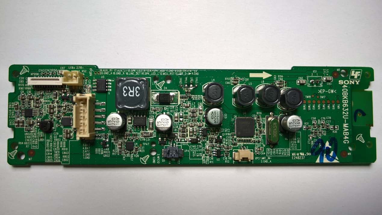
Click to zoom
Application Details
- Equipment Class
- DSS - Part 15 Spread Spectrum Transmitter
- Date of Grant
- Nov 14, 2015
- Application Purpose
- Original Equipment
- Date of Application
- Nov 08, 2015
- Equipment Note
- Bluetooth Module
- Frequency Range
- 2402.00000000 - 2480.00000000
- Company
- Sony Group Corporation
- Country
- Japan
Documents & Files
Document Text
Text extracted from the exhibit documents filed with the FCC. Open a document above to read the original.
Users Manual
External photo Sony Corporation Personal Audio System [Model: SRS-XB2] Installation manual 1. PCB EUT (BT Module): TOP side Bluetooth module (RF block) soldered on the mainboard. EUT (BT Module): Bottom side RF block Jack PCB: NFC board: 2. Installation steps As you see, the main board is fixed with the bracket Then the EUT (BT Module) connected with other things After that the EUT (BT Module) with bracket was mounted in the machine chamber , as below: Main board with bracket At last, the machine is sealed: So, it will be not to open RF block easily!
Users Manual
SRS-XB2 UC7/CA (US/CaFR/LaES) 4-XXX-XXX-11(1) EnglishPersonal Audio System Before operating the system, please read this guide thoroughly and retain it for future reference. Owner’s Record The serial number is located on the bottom of the product. Record the serial number in the space provided below. Refer to them whenever you call upon your Sony dealer regarding this product. Model No. SRS-XB2 Serial No. For customers in the USA Please register this product on line at http://www.sony.com/productregistration Proper registration will enable us to send you periodic updates about new products, services and other important announcements. Registering your product will also allow us to contact you in the unlikely event that the product needs adjustment or modification. Thank you. WARNING IMPORTANT SAFETY INSTRUCTIONS – SAVE THESE INSTRUCTIONS. DANGER – TO REDUCE THE RISK OF FIRE OR ELECTRIC SHOCK, CAREFULLY FOLLOW THESE INSTRUCTIONS. To reduce the risk of fire or electric shock, do not expose this apparatus to rain or moisture. To reduce the risk of fire, do not cover the ventilation opening of the appliance with newspapers, tablecloths, curtains, etc. Do not expose the appliance to naked flame sources (for example, lighted candles). To reduce the risk of fire or electric shock, do not expose this apparatus to dripping or splashing, and do not place objects filled with liquids, such as vases, on the apparatus. Do not install the appliance in a confined space, such as a bookcase or built-in cabinet. Do not expose the batteries (battery pack or batteries installed) to excessive heat such as sunshine, fire or the like for a long time. As the main plug of USB AC adaptor is used to disconnect the USB AC adaptor from the mains, connect it to an easily accessible AC outlet. Should you notice an abnormality in it, disconnect it from the AC outlet immediately. The unit is not disconnected from the AC power source (mains) as long as it is connected to the wall outlet, even if the unit itself has been turned off. Dispose of used battery promptly, according to local environmental laws and guidelines in force. For connection to a supply not in the U.S.A., use an attachment plug adapter of the proper configuration for the power outlet, if needed. CAUTION You are cautioned that any changes or modifications not expressly approved in this manual could void your authority to operate this equipment. NOTE: This equipment has been tested and found to comply with the limits for a Class B digital device, pursuant to Part 15 of the FCC Rules. These limits are designed to provide reasonable protection against harmful interference in a residential installation. This equipment generates, uses and can radiate radio frequency energy and, if not installed and used in accordance with the instructions, may cause harmful interference to radio communications. However, there is no guarantee that interference will not occur in a particular installation. If this equipment does cause harmful interference to radio or television reception, which can be determined by turning the equipment off and on, the user is encouraged to try to correct the interference by one or more of the following measures: Reorient or relocate the receiving antenna. Increase the separation between the equipment and receiver. Connect the equipment into an outlet on a circuit different from that to which the receiver is connected. Consult the dealer or an experienced radio/TV technician for help. This equipment complies with FCC/IC radiation exposure limits set forth for an uncontrolled environment and meets the FCC radio frequency (RF) Exposure Guidelines and RSS-102 of the IC radio frequency (RF) Exposure rules. This equipment has very low levels of RF energy that it deemed to comply without maximum permissive exposure evaluation (MPE). This equipment must not be co-located or operated in conjunction with any other antenna or transmitter. If your skin touches the USB AC adaptor or this product for a long time when the power is on, it may cause a low temperature injury. For customers in the USA and Canada For the state of California, USA only Perchlorate Material - special handling may apply, See www.dtsc.ca.gov/hazardouswaste/perchlorate Perchlorate Material : Lithium battery contains perchlorate For customers in Canada This device complies with Industry Canada’s licence-exempt RSSs. Operation is subject to the following two conditions: (1) This device may not cause interference, and (2) This device must accept any interference, including interference that may cause undesired operation of the device. Important Safety Instructions 1) Read these instructions. 2) Keep these instructions. 3) Heed all warnings. 4) Follow all instructions. 5) Do not use this apparatus near water. 6) Clean only with dry cloth. 7) Do not block any ventilation openings. Install in accordance with the manufacturer’s instructions. 8) Do not install near any heat sources such as radiators, heat registers, stoves, or other apparatus (including amplifiers) that produce heat. 9) Do not defeat the safety purpose of the polarized or grounding-type plug. A polarized plug has two blades with one wider than the other. A grounding type plug has two blades and a third grounding prong. The wide blade or the third prong are provided for your safety. If the provided plug does not fit into your outlet, consult an electrician for replacement of the obsolete outlet. 10) Protect the power cord from being walked on or pinched particularly at plugs, convenience receptacles, and the point where they exit from the apparatus. 11) Only use attachments/accessories specified by the manufacturer. 12) Use only with the cart, stand, tripod, bracket, or table specified by the manufacturer, or sold with the apparatus. When a cart is used, use caution when moving the cart/apparatus combination to avoid injury from tip-over. 13) Unplug this apparatus during lightning storms or when unused for long periods of t…
Text truncated - open the document above for the full version.
Cover Letter(s)
SONY Sony Corporation 1-7-1 Konan Minato-Ku, Tokyo 108-0075 Japan Date: October. 9 th , 2015 Federal Communications Commission Authorization and Evaluation Division FCC ID: AK8BM63 N Confidentiality Request Pursuant to Sections 0.457 and 0.459 of the Commission’s Rules, the Applicant hereby requests confidential treatment of information accompanying this application as outlined below: 1. Block diagram 2. Schematics 3. Operation Description The above materials contain trade secrets and proprietary information not customarily released to the public. The public disclosure of these matters might to harmful to the applicant and provide unjustified benefits to its competitors. The applicant understands that pursuant to Rule 0.457, disclosure of this application and all accompanying documentation will not be made before the date of the grant for this application. Sincerely, Kazunaga Kinjo Senior Product Safety Manager SVP/SVS Section, Products Compliance Department, Quality & Environmental Division, Sony Corporation Tel: +81-50-3750-7634 Fax: +81-50-3750-6573 E-mail: [email protected]
Cover Letter(s)
SONY Sony Corporation 1-7-1 Konan Minato-Ku, Tokyo 108-0075 Japan Modular Approval Request Letter Dear Application Examiner, Sony Corporation, It’s Bluetooth Module , FCC ID: AK8BM63N, would like to have your authorization as a modular approval specific to the mobile device such as Personal Audio System SRS-XB2 . The requirements of section 15.212 have been met and shown on the following statements. 1, “The modular transmitter must have it’s own RF shielding.”The modular transmitter don’t have RF shielding. 2, “The modular transmitter must have buffered modulation data inputs.” The EUT has buffered data inputs. 3,“The modular transmitter have it’s own power supply regulation.” The USB interface provides 5V DC,the on board regulator AS2910 convert 5V DC to3.3V DC. 4,“The modular transmitter must comply with antenna requirements of section 15.203 and 15.204(c).” The EUT meets the FCC antenna requirements, it’s an integral PCB antenna and have no antenna connector. The spurious emissions are shown in the test report. 5, “The modular transmitter must be tested in a stand-alone configuration" This module was installed inside of the host device SRS-XB2 for the test. 6, “The modular transmitter must be labeled with it’s own FCC ID number.” Please see exhibition Label Sample for the FCC ID of this module. And also in the exhibition User Manual, there are instructions give to the OEM on how to label the end product. 7, “The modular transmitter must comply with any specific rule or operating requirements applicable to the transmitter and the manufacture must provide adequate instructions along with module to explain any such requirement.” The EUT is compliant with all applicable FCC rules, detail instructions for maintaining compliance are given in the users Manual. 8, “The modular transmitter must comply with any applicable RF exposure requirements.” The EUT is compliant with all applicable RF exposure requirements. RF exposure is addressed in the test report. Best Regards. Kazunaga Kinjo Senior Product Safety Manager SVP/SVS Section, Product Compliance Department Quality & Environmental Division Sony Corporation Tel:+81-50-3750-7634 Fax: +81-50-3750-6572 E-mail:[email protected]
External Photos
Antenna location photo Sony Corporation Personal Audio System [Model: SRS-XB2] Antenna BT module Antenna location photo Sony Corporation Personal Audio System [Model: SRS-XB2]
ID Label/Location Info
Label of EUT
Internal Photos
Antenna location photo Sony Corporation Personal Audio System [Model: SRS-XB2] Antenna BT module Antenna location photo Sony Corporation Personal Audio System [Model: SRS-XB2]
RF Exposure Info
Product Name:Bluetooth Module Model Number: BM63 FCC ID: AK8BM63N RADIO FRREQUENCY EXPOSURE COMPLIANCE RESULT : Test Standard : FCC KDB Publication 447498 D01 V05R02 Clause 4.3.1, The 1‐g and 10‐g SAR test exclusion thresholds for 100 MHz to 6 GHz at test separation distances ≤ 50 mm are determined by: [(max. power of channel, including tune‐up tolerance, mW)/(min. test separation distance, mm)] ∙ [√f (GHz) ] ≤ 3.0 for 1‐g SAR and ≤ 7.5 for 10‐g extremity SAR, where ‧ f (GHz) is the RF channel transmit frequency in GHz ‧ Power and distance are rounded to the nearest mW and mm before calculation ‧ The result is rounded to one decimal place for comparison ‧ 3.0 and 7.5 are referred to as the numeric thresholds in the step 2 below The test exclusions are applicable only when the minimum test separation distance is ≤ 50 mm and for transmission frequencies between 100 MHz and 6 GHz. When the minimum test separation distance is < 5 mm, a distance of 5 mm according to 5) in section 4.1 is applied to determine SAR test exclusion. According to the actual measurement, max. power of channel, including tune‐up tolerance =2.045mW min. test separation distance= 5mm √f (GHz) =1.55 The test result is 0.63395 ≤ 3.0 for 1‐g SAR ≤ 7.5 for 10‐g SAR, hence the EUT is excluded from SAR evaluation according to FCC KDB Publication 447498 D01: General RF Exposure Guidance V05.
Test Report
R AUDIX Technology (Shenzhen) Co., Ltd. FCC ID:AK8BM63N Audix Technology (Shenzhen) Co., Ltd. Report No. ACS-F15276 FCC PART 15C TEST REPORT FOR CERTIFICATION On Behalf of Sony Corporation Bluetooth Module Model No.: BM63 FCC ID: AK8BM63N Prepared for : Sony Corporation 1-7-1 Konan, Minato-ku, Tokyo 108-0075 Japan Prepared By : Audix Technology (Shenzhen) Co., Ltd. No. 6, Ke Feng Rd., 52 Block, Shenzhen Science & Industrial Park, Nantou, Shenzhen, Guangdong, China Tel: (0755) 26639496 Report Number : ACS-F15276 Date of Test : Sep.11~19, 2015 Date of Report : Oct.30, 2015 R AUDIX Technology (Shenzhen) Co., Ltd. FCC ID:AK8BM63N Audix Technology (Shenzhen) Co., Ltd. Report No. ACS-F15276 TABLE OF CONTENTS Description Page 1. SUMMARY OF STANDARDS AND RESULTS .......................................................... 1-1 1.1. Description of Standards and Results .................................................................................. 1-1 2. GENERAL INFORMATION ......................................................................................... 2-1 2.1. Description of Device (EUT) ............................................................................................... 2-1 2.2. Tested Supporting System Details ....................................................................................... 2-2 2.3. Block Diagram of connection between EUT and simulators ............................................... 2-2 2.4. Test information ................................................................................................................... 2-2 2.5. Test Facility ......................................................................................................................... 2-3 2.6. Measurement Uncertainty (95% confidence levels, k=2) .................................................... 2-3 3. POWER LINE CONDUCTED EMISSION TEST ....................................................... 3-1 3.1. Test Equipments ................................................................................................................... 3-1 3.2. Block Diagram of Test Setup ............................................................................................... 3-1 3.3. Power Line Conducted Emission Test Limits ...................................................................... 3-1 3.4. Configuration of EUT on Test ............................................................................................. 3-2 3.5. Operating Condition of EUT ............................................................................................... 3-2 3.6. Test Procedure ..................................................................................................................... 3-2 3.7. Power Line Conducted Emission Test Results .................................................................... 3-2 4. RADIATED EMISSION MEASUREMENT ................................................................. 4-1 4.1. Test Equipment .................................................................................................................... 4-1 4.2. Block Diagram of Test Setup ............................................................................................... 4-1 4.3. Radiated Emission Limit Standard: ..................................................................................... 4-2 4.4. EUT Configuration on Test ................................................................................................. 4-2 4.5. Operating Condition of EUT ............................................................................................... 4-2 4.6. Test Procedure ..................................................................................................................... 4-2 4.7. Radiated Emission Test Results ........................................................................................... 4-3 5. CONDUCTED SPURIOUS EMISSIONS ...................................................................... 5-1 5.1. Test Equipment .................................................................................................................... 5-1 5.2. Limit ..................................................................................................................................... 5-1 5.3. Test Procedure ..................................................................................................................... 5-1 5.4. Test result ............................................................................................................................. 5-1 6. 20 DB BANDWIDTH TEST ........................................................................................... 6-1 6.1. Test Equipment .................................................................................................................... 6-1 6.2. Limit ..................................................................................................................................... 6-1 6.3. Test Results .......................................................................................................................... 6-1 7. CARRIER FREQUENCY SEPARATION TEST ........................................................ 7-1 7.1. Test Equipment .................................................................................................................... 7-1 7.2. Limit ..................................................................................................................................... 7-1 7.3. Test Results. ......................................................................................................................... 7-1 8. NUMBER OF HOPPING FREQUENCY TEST .......................................................... 8-1 8.1. Test Equipment .................................................................................................................... 8-1 8.2. Limit ..........................................................…
Text truncated - open the document above for the full version.
Test Setup Photos
R AUDIX Technology (Shenzhen) Co., Ltd. FCC ID:AK8BM63N page 14-1 Audix Technology (Shenzhen) Co., Ltd. Report No. ACS-F15276 14. PHOTOGRAPH OF TEST 14.1.Photos of Power Line Conducted Emission Test R AUDIX Technology (Shenzhen) Co., Ltd. FCC ID:AK8BM63N page 14-2 Audix Technology (Shenzhen) Co., Ltd. Report No. ACS-F15276 14.2.Photos of Radiated Emission Test 30-1000MHz R AUDIX Technology (Shenzhen) Co., Ltd. FCC ID:AK8BM63N page 14-3 Audix Technology (Shenzhen) Co., Ltd. Report No. ACS-F15276 Above 1000MHz
Contact Information
Applicant
Kazuyuki Hori(Chief EMC/RF Compliance Specialist)
Technical Contact
AUDIX Technology (Shenzhen) Co., Ltd.
[email protected]86-755-26639497
52 Block Shenzhen Science&Industry · Shenzhen · China
Non-Technical Contact
AUDIX Technology (Shenzhen) Co., Ltd.
[email protected]86-755-26639497
Test Firm
Audix Technology (Shenzhen) Co., Ltd.Smart Tsai
Technical Specifications
| # | Rule Parts | Frequency Range | Power Output |
|---|---|---|---|
| 1 | 15C | 2.40 GHz - 2.48 GHz | 2.04 mW |
Other Applications from Sony Group Corporation
AK8WW81782
Aug 21, 2026Radio Equipment
Equipment Class
DSS - Part 15 Spread Spectrum TransmitterAK8CFIZCP2
Aug 03, 2026Wireless Controller
Equipment Class
DSS - Part 15 Spread Spectrum TransmitterAK8OEV321MUH
Apr 14, 2026LCD Monitor
Equipment Class
JAD - Part 15 Class A Digital DeviceAK8OEV431MUH
Apr 14, 2026LCD Monitor
Equipment Class
JAD - Part 15 Class A Digital DeviceAK8OEV271MUH
Apr 14, 2026LCD Monitor
Equipment Class
JAD - Part 15 Class A Digital Device