AK8COM2Personal Communicator
Sony Group Corporation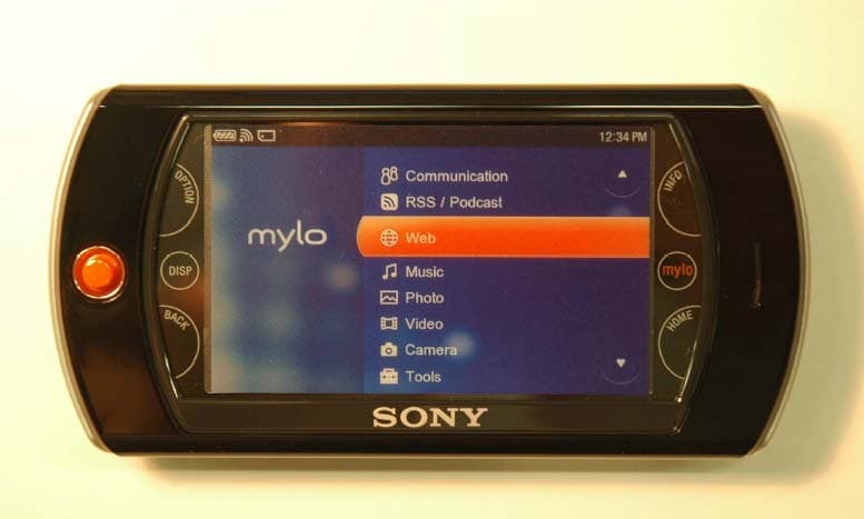
Click to zoom
Application Details
- Equipment Class
- DTS - Digital Transmission System
- Date of Grant
- Dec 15, 2007
- Application Purpose
- Original Equipment
- Date of Application
- Dec 12, 2007
- Equipment Note
- Personal Communicator
- Frequency Range
- 2412.00000000 - 2462.00000000
- Company
- Sony Group Corporation
- Country
- Japan
Documents & Files
Document Text
Text extracted from the exhibit documents filed with the FCC. Open a document above to read the original.
Users Manual
COM-2.US.3-213-854-11(1) 3-213-854-11(1) © 2008 Sony Corporation Quick Start Guide Personal Communicator COM-2 Owner’s Record Th e serial number is located inside the battery compartment. Record the serial number in the space provided below. Refer to these numbers when you call your Sony Service Center. Model No. COM-2 Serial No. _______________________ WARNING You are cautioned that any changes or modifi cations not expressly approved in this manual could void your authority to operate this equipment. Th is equipment has been tested and found to comply with the limits for a Class B digital device, pursuant to Part 15 of the FCC Rules. Th ese limits are designed to provide reasonable protection against harmful interference in a residential installation. Th is equipment generates, uses, and can radiate radio frequency energy and, if not installed and used in accordance with the instructions, may cause harmful interference to radio communications. However, there is no guarantee that interference will not occur in a particular installation. If this equipment does cause harmful interference to radio or television reception, which can be determined by turning the equipment off and on, the user is encouraged to try to correct the interference by one or more of the following measures: – Reorient or relocate the receiving antenna. – Increase the separation between the equipment and receiver. – Connect the equipment into an outlet on a circuit diff erent from that to which the receiver is connected. – Consult the dealer or an experienced radio/TV technician for help Th e available scientifi c evidence does not show that any health problems are associated with using low power wireless devices. Th ere is no proof, however, that these low power wireless devices are absolutely safe. Low power Wireless devices emit low levels of radio frequency energy (RF) in the microwave range while being used. Whereas high levels of RF can produce health eff ects (by heating tissue), exposure to low level RF that does not produce heating eff ects causes no known adverse health eff ects. Many studies of low level RF exposures have not found any biological eff ects. Some studies have suggested that some biological eff ects might occur, but such fi ndings have not been confi rmed by additional research. Th e Perso n and found uncontrolle Guidelines Please refer Th is device other anten to modify t device coul Th is device to the follo interferenc including i Th e supplie comply wit FCC Rules COM-2.US.3-213-854-11(1) 2 COM-2.US rd the when you approved t. ts for a limits rference n radiate e with ications. a particular adio or pment off one or m that to elp blems are f, however, er Wireless owave alth eff ects heating w level RF suggested t been Th e Personal Communicator COM-2 (FCC ID: AK8COM2) has been tested and found to comply with FCC radiation exposure limits set forth for an uncontrolled equipment and meets the FCC radio frequency (RF) Exposure Guidelines in Supplement C to OET65. Please refer to the SAR test report that was uploaded at FCC website. Th is device and its antenna(s) must not be co-located or operating with any other antenna or transmitter except Grant condition. Users are not permitted to modify this transmitter device. Any unauthorized change made to this device could void your authority to operate this device. Th is device complies with Part 15 of the FCC Rules. Operation is subject to the following two conditions: (1) this device may not cause harmful interference, and (2) this device must accept any interference received, including interference that may cause undesired operation. Th e supplied interface cable must be used with the equipment in order to comply with the limits for a digital device pursuant to Subpart B of Part 15 of FCC Rules. 3 COM-2.US.3-213-854-11(1) Important Safety Instructions Save these Instructions. Danger To reduce the risk of fi re or electric shock, carefully follow these instructions. For connection to a supply not in the U.S.A., use an attachment plug adapter of the proper confi guration for the power outlet. Do not expose the unit to rain or moisture. Do not open the cabinet. Refer servicing to qualifi ed personnel only. Th e socket outlet shall be located near the equipment and shall be easily accessible. Th ere is a danger of explosion exists if battery is incorrectly replaced. Replace only with the same or equivalent type recommended by the manufacturer. Discard used batteries according to the manufacturer’s instructions. Th e battery pack used in this device may present a fi re or chemical burn hazard if mistreated. Do not disassemble, heat above 140°F (60°C) or incinerate. Do not short circuit. Dispose of used battery promptly. Keep away from children. Caution Do not use wireless LAN on hospital premises. Doing so may cause medical devices to malfunction. Do not use wireless LAN on an aircraft , as doing so may cause the aircraft 's equipment to malfunction. If using wireless LAN near a pacemaker, make sure it is at least 8 inches (20 cm) away from the pacemaker. Sony is not responsible for any interference that you may experience or that may be caused when operating this device. Wireless LAN Security Creating security settings for the Wireless LAN is important. Sony assumes no responsibility for any security problems that may arise from the use of the Wireless LAN. If you hav Visit: http://www Contact: Sony Custo Write: Sony Custo 12451 Gate Ft. Myers, F For an accesso 1-800-488- Declaration Trade Na Model N Responsi Address: Telepho n • “mylo” and COM-2.US.3-213-854-11(1) 4 COM-2.US structions. ug adapter y. easily ed. Replace acturer. s. burn or Keep away e medical aircraft 's nches (20 ce or that assumes use of the If you have any questions about this product: Visit: http://www.sony.com/mylo Contact: Sony Customer Information Services Center at 1-866-420-7669 Write: Sony Customer Information Services Center 12451 Gateway Blvd., Ft. Myers, FL 33913 For an a…
Text truncated - open the document above for the full version.
External Photos
External Photo Sony Corporation Personal Communicator [Model: COM-2] FCC ID: AK8COM2 Front Rear External Photo Sony Corporation Personal Communicator [Model: COM-2] FCC ID: AK8COM2 Top Bottom External Photo Sony Corporation Personal Communicator [Model: COM-2] FCC ID: AK8COM2 Right Left
ID Label/Location Info
Label size: 75 mm x 18 mm The FCC statement is described to the user manual. Because the front side is a liquid crystal screen, and the back side is an operation part, the displayof the statement is difficult
Internal Photos
Internal Photo Sony Corporation Personal Communicator [Model: COM-2] FCC ID: AK8COM2 PWB Antenna Location Internal Photo Sony Corporation Personal Communicator [Model: COM-2] FCC ID: AK8COM2 RF Module (Top) RF Module (Bottom) Internal Photo Sony Corporation Personal Communicator [Model: COM-2] FCC ID: AK8COM2 RF Module with Shield(Top)
Test Report
Test report No. : 28BE0121-HO-02-A-R1 Page : 2 of 59 Issued date : November 30, 2007 Revised date : December 7, 2007 FCC ID : AK8COM2 UL Japan, Inc. Head Office EMC Lab. 4383-326 Asama-cho, Ise-shi, Mie-ken 516-0021 JAPAN Telephone : +81 596 24 8116 Facsimile : +81 596 24 8124 CONTENTS PAGE SECTION 1: Client information ............................................................................................................ 3 SECTION 2: Equipment under test (E.U.T.)........................................................................................ 3 SECTION 3: Test specification, procedures & results......................................................................... 4 SECTION 4: Operation of E.U.T. during testing .................................................................................8 SECTION 5: Conducted Emission......................................................................................................... 9 SECTION 6: Spurious Emission.......................................................................................................... 10 SECTION 7: Bandwidth ....................................................................................................................... 11 SECTION 8: Maximum Peak Output Power ..................................................................................... 11 SECTION 9: Peak Power Density........................................................................................................ 11 APPENDIX 1: Photographs of test setup ............................................................................................ 12 Conducted Emission ........................................................................................................ 12 Spurious Emission (Radiated) ........................................................................................ 13 Worst Case Position (Horizontal: Y-axis/ Vertical:Z-axis) ......................................... 14 APPENDIX 2: Data of EMI test............................................................................................................ 15 Conducted Emission ........................................................................................................ 15 6dB Bandwidth ................................................................................................................ 23 Maximum Peak Output Power....................................................................................... 26 Radiated Spurious Emission (below 1GHz) .................................................................. 28 Radiated Spurious Emission (above 1GHz) .................................................................. 36 Conducted Spurious Emission........................................................................................ 44 Conducted emission Band Edge compliance................................................................. 52 Power Density ..................................................................................................................53 99%Occupied Bandwidth ............................................................................................... 56 APPENDIX 3:Test instruments ............................................................................................................ 58 Test report No. : 28BE0121-HO-02-A-R1 Page : 3 of 59 Issued date : November 30, 2007 Revised date : December 7, 2007 FCC ID : AK8COM2 UL Japan, Inc. Head Office EMC Lab. 4383-326 Asama-cho, Ise-shi, Mie-ken 516-0021 JAPAN Telephone : +81 596 24 8116 Facsimile : +81 596 24 8124 SECTION 1: Client information Company Name : Sony EMCS Corporation Nagano TEC * Address : 5432 Toyoshina, Azumino-shi, Nagano 399-8282 Japan Telephone Number : +81-263-72-5696 Facsimile Number : +81-263-72-9755 Contact Person : Masami Ogawa * Sony EMCS Corporation Nagano TEC is on behalf of the applicant: Sony Corporation. SECTION 2: Equipment under test (E.U.T.) 2.1 Identification of E.U.T. Type of Equipment : Personal Communicator Model No. : COM-2 Serial No. : 30610230 3000044 Country of Manufacture : Japan Receipt Date of Sample : November 15, 2007 Condition of EUT : Engineering prototype (Not for Sale: This sample is equivalent to mass-produced items.) Modification of EUT : No modification by the test lab. 2.2 Product Description Model No: COM-2 is the Personal Communicator. Equipment Type : Transceiver Frequency of Operation : 2412 – 2462MHz Other Clock Frequency : 133MHz, 39MHz, 12MHz Type of Modulation : DSSS, OFDM Antenna Type : Inverted F type Antenna Gain : -0.21dBi Antenna Connector Type : I-PEX MHF2 Power Supply : DC3.0V and DC1.8V Test report No. : 28BE0121-HO-02-A-R1 Page : 4 of 59 Issued date : November 30, 2007 Revised date : December 7, 2007 FCC ID : AK8COM2 UL Japan, Inc. Head Office EMC Lab. 4383-326 Asama-cho, Ise-shi, Mie-ken 516-0021 JAPAN Telephone : +81 596 24 8116 Facsimile : +81 596 24 8124 SECTION 3: Test specification, procedures & results 3.1 Test Specification Test Specification : FCC Part15 Subpart C: 2007 Title : FCC 47CFR Part15 Radio Frequency Device Subpart C Intentional Radiators Section 15.207 Conducted limits Section 15.247 Operation within the bands 902-928MHz, 2400-2483.5MHz, and 5725-5850MHz FCC 15.31 (e) This EUT provides stable voltage (DC3.0V and DC1.8V) constantly to RF Module regardless of input voltage. Therefore, this EUT complies with the requirement. FCC Part 15.203 Antenna requirement It is impossible for end users to replace the antenna, because the antenna is mounted inside of the EUT. Therefore, the equipment complies with the antenna requirement of Section 15.203. Test report No. : 28BE0121-HO-02-A-R1 Page : 5 of 59 Issued date : November 30, 2007 Revised date : December 7, 2007 FCC ID : AK8COM2 UL Japan, Inc. Head Office EMC Lab. 4383-326 Asama-cho, Ise-shi, Mie-ken 516-0021 JAPAN Telephone : +81 596 24 8116 Facsimile : +81 596 24 8124 3.2 Procedures and results No. Item Test Procedure…
Text truncated - open the document above for the full version.
Test Report
Test report No. : 28BE0121-HO-02-A-R1 Page : 15 of 59 Issued date : November 30, 2007 Revised date : December 7, 2007 FCC ID : AK8COM2 UL Japan, Inc. Head Office EMC Lab. 4383-326 Asama-cho, Ise-shi, Mie-ken 516-0021 JAPAN Telephone : +81 596 24 8116 Facsimile : +81 596 24 8124 APPENDIX 2: Data of EMI test Conducted Emission Tx, 11b, Ch:Low DATA OF CONDUCTED EMISSION TEST UL Japan,Inc. Head Office EMC Lab. No.3 Semi Anechoic Chamber Date : 2007/11/19 Company : SONY CORPORATION Report No. : 28BE0121-HO-02 Kind of EUT : Personal Communicator Power : AC120V / 60Hz Model No. : COM-2 Temp./Humi. : 23deg.C / 31% Serial No. : 30610230 3000044 Operator : Hisayoshi Sato Mode / Remarks : Transmitting 11b 2412MHz 11Mbps LIMIT : FCC15.207 QP FCC15.207 AV CHART:WITH FACTOR,Peak hold data. CALCURATION:RESULT[dBuA]=READING[dBuV]+C.F[dB](Probe Fac+CABLE LOSS) Data is uncorrected. Except for the above table: adequate margin data below the limits. Frequency[Hz] [dBuV]<< PEAK DATA >> N:PEAK .15M30M.2M.3M.5M.7M1M2M3M5M7M10M20M 0 10 20 30 40 50 60 70 80 90 100 Frequency[Hz] [dBuV]<< PEAK DATA >> L:PEAK .15M30M.2M.3M.5M.7M1M2M3M5M7M10M20M 0 10 20 30 40 50 60 70 80 90 100 *The test result is round off to one or two decimal places, so some differences might be observed. Test report No. : 28BE0121-HO-02-A-R1 Page : 16 of 59 Issued date : November 30, 2007 Revised date : December 7, 2007 FCC ID : AK8COM2 UL Japan, Inc. Head Office EMC Lab. 4383-326 Asama-cho, Ise-shi, Mie-ken 516-0021 JAPAN Telephone : +81 596 24 8116 Facsimile : +81 596 24 8124 Conducted Emission Tx, 11b, Ch:Mid DATA OF CONDUCTED EMISSION TEST UL Japan,Inc. Head Office EMC Lab. No.3 Semi Anechoic Chamber Date : 2007/11/19 Company : SONY CORPORATION Report No. : 28BE0121-HO-02 Kind of EUT : Personal Communicator Power : AC120V / 60Hz Model No. : COM-2 Temp./Humi. : 23deg.C / 31% Serial No. : 30610230 3000044 Operator : Hisayoshi Sato Mode / Remarks : Transmitting 11b 2437MHz 11Mbps LIMIT : FCC15.207 QP FCC15.207 AV CHART:WITH FACTOR,Peak hold data. CALCURATION:RESULT[dBuA]=READING[dBuV]+C.F[dB](Probe Fac+CABLE LOSS) Data is uncorrected. Except for the above table: adequate margin data below the limits. Frequency[Hz] [dBuV]<< QP/AV DATA >> L:QP:AV N:QP:AV .15M30M.2M.3M.5M.7M1M2M3M5M7M10M20M 0 10 20 30 40 50 60 70 80 90 100 Frequency Reading LevelReading LevelCorr.ResultsResultsLimitLimitMarginMargin Phase Frequency QPAVFactorQPAVQPAVQPAVPhase [MHz][dBuV][dBuV][dB][dBuV][dBuV][dBuV][dBuV][dB][dB] Phase 0.2022044.239.10.444.639.563.553.518.914.0L 0.3044635.033.60.435.434.060.150.124.716.1L 0.4053032.831.70.433.232.157.747.724.515.6L 0.6064728.927.70.429.328.156.046.026.717.9L 0.8090530.228.60.430.629.056.046.025.417.0L 3.7395529.128.61.030.129.656.046.025.916.4L 0.2029544.636.30.445.036.763.553.518.516.8N 0.3023537.934.60.438.335.060.250.221.915.2N 0.4046535.234.60.435.635.057.847.822.212.8N 0.6071031.931.90.432.332.356.046.023.713.7N 0.8084132.632.90.433.033.356.046.023.012.7N 4.1403128.127.91.229.329.156.046.026.716.9N *The test result is round off to one or two decimal places, so some differences might be observed. Test report No. : 28BE0121-HO-02-A-R1 Page : 17 of 59 Issued date : November 30, 2007 Revised date : December 7, 2007 FCC ID : AK8COM2 UL Japan, Inc. Head Office EMC Lab. 4383-326 Asama-cho, Ise-shi, Mie-ken 516-0021 JAPAN Telephone : +81 596 24 8116 Facsimile : +81 596 24 8124 Conducted Emission Tx, 11b, Ch:High DATA OF CONDUCTED EMISSION TEST UL Japan,Inc. Head Office EMC Lab. No.3 Semi Anechoic Chamber Date : 2007/11/19 Company : SONY CORPORATION Report No. : 28BE0121-HO-02 Kind of EUT : Personal Communicator Power : AC120V / 60Hz Model No. : COM-2 Temp./Humi. : 23deg.C / 31% Serial No. : 30610230 3000044 Operator : Hisayoshi Sato Mode / Remarks : Transmitting 11b 2462MHz 11Mbps LIMIT : FCC15.207 QP FCC15.207 AV CHART:WITH FACTOR,Peak hold data. CALCURATION:RESULT[dBuA]=READING[dBuV]+C.F[dB](Probe Fac+CABLE LOSS) Data is uncorrected. Except for the above table: adequate margin data below the limits. Frequency[Hz] [dBuV]<< PEAK DATA >> N:PEAK .15M30M.2M.3M.5M.7M1M2M3M5M7M10M20M 0 10 20 30 40 50 60 70 80 90 100 Frequency[Hz] [dBuV]<< PEAK DATA >> L:PEAK .15M30M.2M.3M.5M.7M1M2M3M5M7M10M20M 0 10 20 30 40 50 60 70 80 90 100 *The test result is round off to one or two decimal places, so some differences might be observed. Test report No. : 28BE0121-HO-02-A-R1 Page : 18 of 59 Issued date : November 30, 2007 Revised date : December 7, 2007 FCC ID : AK8COM2 UL Japan, Inc. Head Office EMC Lab. 4383-326 Asama-cho, Ise-shi, Mie-ken 516-0021 JAPAN Telephone : +81 596 24 8116 Facsimile : +81 596 24 8124 Conducted Emission Tx, 11g, Ch:Low DATA OF CONDUCTED EMISSION TEST UL Japan,Inc. Head Office EMC Lab. No.3 Semi Anechoic Chamber Date : 2007/11/19 Company : SONY CORPORATION Report No. : 28BE0121-HO-02 Kind of EUT : Personal Communicator Power : AC120V / 60Hz Model No. : COM-2 Temp./Humi. : 23deg.C / 31% Serial No. : 30610230 3000044 Operator : Hisayoshi Sato Mode / Remarks : Transmitting 11g 2412MHz 48Mbps LIMIT : FCC15.207 QP FCC15.207 AV CHART:WITH FACTOR,Peak hold data. CALCURATION:RESULT[dBuA]=READING[dBuV]+C.F[dB](Probe Fac+CABLE LOSS) Data is uncorrected. Except for the above table: adequate margin data below the limits. Frequency[Hz] [dBuV]<< PEAK DATA >> N:PEAK .15M30M.2M.3M.5M.7M1M2M3M5M7M10M20M 0 10 20 30 40 50 60 70 80 90 100 Frequency[Hz] [dBuV]<< PEAK DATA >> L:PEAK .15M30M.2M.3M.5M.7M1M2M3M5M7M10M20M 0 10 20 30 40 50 60 70 80 90 100 *The test result is round off to one or two decimal places, so some differences might be observed. Test report No. : 28BE0121-HO-02-A-R1 Page : 19 of 59 Issued date : November 30, 2007 Revised date : December 7, 2007 FCC ID : AK8COM2 UL Japan, Inc. Head Office EMC Lab. 4383-326 Asama-cho, Ise-shi, Mie-ken 516-0021 JAPAN Telephone : +81 596 24 8116 Facsimile : +81 596 24 8124 Conducted Emission Tx, 11g, Ch:Mid DATA OF CONDUCTED EMISSION TEST UL Japan,Inc. Head Office EMC Lab. No.3 Semi Anechoic Chamber Da…
Text truncated - open the document above for the full version.
Test Report
Test report No. : 28BE0121-HO-02-B-R1 Page : 2 of 119 Issued date : December 3, 2007 Revised date : December 7, 2007 FCC ID : AK8COM2 UL Japan, Inc. Head Office EMC Lab. 4383-326 Asama-cho, Ise-shi, Mie-ken 516-0021 JAPAN Telephone : +81 596 24 8116 Facsimile : +81 596 24 8124 CONTENTS PAGE SECTION 1: Client information ............................................................................................................ 4 SECTION 2 : Equipment under test (E.U.T.)....................................................................................... 4 2.1 Identification of E.U.T.................................................................................................4 2.2 Product Description....................................................................................................4 SECTION 3 : Test standard information ............................................................................................... 5 3.1 Requirements for compliance testing defined by the FCC...................................................5 3.2 Exposure limit...........................................................................................................5 3.3 Result of Maximum. SAR value ....................................................................................6 3.4 Test Location............................................................................................................6 SECTION 4 : Operation of E.U.T. during testing ................................................................................6 4.1 Confirmation before SAR testing...................................................................................6 4.2 Confirmation after SAR testing.....................................................................................6 4.3 Operating modes for SAR testing ..................................................................................7 4.4 Measurement procedure...............................................................................................7 4.5 Description of the head test setup..................................................................................8 4.6 Test setup of EUT ....................................................................................................10 SECTION 5 : Test surrounding ........................................................................................................... 11 5.1 Measurement uncertainty...........................................................................................11 SECTION 6 : Confirmation before SAR testing ................................................................................ 12 6.1 EMC Power and SAR Power......................................................................................12 SECTION 7 : Measurement results ..................................................................................................... 15 7.1 Body SAR 2450MHz................................................................................................15 7.2 Head SAR 2450MHz................................................................................................16 Test report No. : 28BE0121-HO-02-B-R1 Page : 3 of 119 Issued date : December 3, 2007 Revised date : December 7, 2007 FCC ID : AK8COM2 UL Japan, Inc. Head Office EMC Lab. 4383-326 Asama-cho, Ise-shi, Mie-ken 516-0021 JAPAN Telephone : +81 596 24 8116 Facsimile : +81 596 24 8124 APPENDIX 1 : Photographs of test setup ........................................................................................... 17 1. Photograph of EUT......................................................................................................................... 17 2. Setup position ................................................................................................................................. 18 3. Antenna position............................................................................................................................. 19 4. EUT with accessories (Body-worn setup) ......................................................................................20 5. Photograph of set up ....................................................................................................................... 21 APPENDIX 2 : SAR Measurement data .............................................................................................35 1. Evaluation procedure ...................................................................................................................... 35 2. Measurement data (Body SAR 2450MHz)..................................................................................... 36 3. Measurement data (Head SAR 2450MHz) ..................................................................................... 61 APPENDIX 3 : Test instruments ......................................................................................................... 77 1. Equipment used .............................................................................................................................. 77 2. Dosimetry assessment setup ........................................................................................................... 78 3. Configuration and peripherals ........................................................................................................ 79 4. System components ........................................................................................................................ 80 5. Test system specifications .............................................................................................................. 83 6. Simulated Tissues Composition...................................................................................................... 85 7. Simulated Tissue Liquid Parameter confirmation .......................................................................... 85 8. System validation data ...........…
Text truncated - open the document above for the full version.
Test Report
Test report No. : 28BE0121-HO-02-B-R1 Page : 35 of 119 Issued date : December 3, 2007 Revised date : December 7, 2007 FCC ID : AK8COM2 UL Japan, Inc. Head Office EMC Lab. 4383-326 Asama-cho, Ise-shi, Mie-ken 516-0021 JAPAN Telephone : +81 596 24 8116 Facsimile : +81 596 24 8124 APPENDIX 2 : SAR Measurement data 1. Evaluation procedure The evaluation was performed with the following procedure: Step 1: Measurement of the E-field at a fixed location above the central position of flat phantom was used as a reference value for assessing the power drop. Step 2: The SAR distribution at the exposed side of body position was measured at a distance of each device from the inner surface of the shell. The area covered the entire dimension of the antenna of EUT and the horizontal grid spacing was 15 mm x 15 mm . Based on these data, the area of the maximum absorption was determined by spline interpolation. Step 3: Around this point found in the Step 2 (area scan) , a volume of 30mm x 30mm x 30mm was assessed by measuring 7 x 7 x 7 points. And for any secondary peaks found in the Step2 which are within 2dB of maximum peak (level more than ambient noise (> 0.012 W/kg)) and not with this Step3 (Zoom scan) is repeated. On the basis of this data set, the spatial peak SAR value was evaluated under the following procedure: (1). The data at the surface were extrapolated, since the center of the dipoles is 1mm away from the tip of the probe and the distance between the surface and the lowest measuring point is 1.3 mm. The extrapolation was based on a least square algorithm [4]. A polynomial of the fourth order was calculated through the points in z-axes. This polynomial was then used to evaluate the points between the surface and the probe tip. (2). The maximum interpolated value was searched with a straightforward algorithm. Around this maximum the SAR values averaged over the spatial volumes (1 g or 10 g) were computed by the 3D-Spline interpolation algorithm. The 3D-Spline is composed of three one-dimensional splines with the “Not a knot"-condition (in x, y and z-directions) [4], [5]. The volume was integrated with the trapezoidal-algorithm. One thousand points (10 x 10 x 10) were interpolated to calculate the average. (3). All neighboring volumes were evaluated until no neighboring volume with a higher average value was found. Step 4: Re-measurement of the E-field at the same location as in Step 1. Test report No. : 28BE0121-HO-02-B-R1 Page : 36 of 119 Issued date : December 3, 2007 Revised date : December 7, 2007 FCC ID : AK8COM2 UL Japan, Inc. Head Office EMC Lab. 4383-326 Asama-cho, Ise-shi, Mie-ken 516-0021 JAPAN Telephone : +81 596 24 8116 Facsimile : +81 596 24 8124 2. Measurement data (Body SAR 2450MHz) COM-2_Body_Front_CCK(11Mbps)_2437MHz Crest factor: 1 Medium: M2450 Medium parameters used: f = 2450 MHz; σ = 1.94 mho/m; ε r = 50.1; ρ = 1000 kg/m 3 Phantom section: Flat Section DASY4 Configuration: - Probe: EX3DV4 - SN3540; ConvF(7.8, 7.8, 7.8); Calibrated: 2007/01/19 - Sensor-Surface: 2mm (Mechanical Surface Detection) - Phantom: SAM 1196 - Measurement SW: DASY4, V4.6 Build 23; Postprocessing SW: SEMCAD, V1.8 Build 160 Area Scan (81x81x1): Measurement grid: dx=15mm, dy=15mm Maximum value of SAR (interpolated) = 0.011 mW/g Zoom Scan (7x7x7)/Cube 0: Measurement grid: dx=5mm, dy=5mm, dz=5mm Reference Value = 1.64 V/m; Power Drift = -0.162 dB Peak SAR (extrapolated) = 0.015 W/kg SAR(1 g) = 0.00859 mW/g; SAR(10 g) = 0.00573 mW/g Maximum value of SAR (measured) = 0.011 mW/g Test Date = 11/28/07 Ambient Temperature = 24.1degree.c Liquid Temperature = Before 23.5 degree.C , After 23.5 degree.C Test report No. : 28BE0121-HO-02-B-R1 Page : 37 of 119 Issued date : December 3, 2007 Revised date : December 7, 2007 FCC ID : AK8COM2 UL Japan, Inc. Head Office EMC Lab. 4383-326 Asama-cho, Ise-shi, Mie-ken 516-0021 JAPAN Telephone : +81 596 24 8116 Facsimile : +81 596 24 8124 COM-2_Body_Bottom_CCK(11Mbps)_2437MHz Crest factor: 1 Medium: M2450 Medium parameters used: f = 2450 MHz; σ = 1.94 mho/m; ε r = 50.1; ρ = 1000 kg/m 3 Phantom section: Flat Section DASY4 Configuration: - Probe: EX3DV4 - SN3540; ConvF(7.8, 7.8, 7.8); Calibrated: 2007/01/19 - Sensor-Surface: 2mm (Mechanical Surface Detection) - Phantom: SAM 1196 - Measurement SW: DASY4, V4.6 Build 23; Postprocessing SW: SEMCAD, V1.8 Build 160 Area Scan (81x81x1): Measurement grid: dx=15mm, dy=15mm Maximum value of SAR (interpolated) = 0.245 mW/g Zoom Scan (7x7x7)/Cube 0: Measurement grid: dx=5mm, dy=5mm, dz=5mm Reference Value = 7.26 V/m; Power Drift = -0.010 dB Peak SAR (extrapolated) = 0.530 W/kg SAR(1 g) = 0.194 mW/g; SAR(10 g) = 0.085 mW/g Maximum value of SAR (measured) = 0.330 mW/g Test Date = 11/28/07 Ambient Temperature = 24.1degree.c Liquid Temperature = Before 23.4 degree.C , After 23.4 degree.C Test report No. : 28BE0121-HO-02-B-R1 Page : 38 of 119 Issued date : December 3, 2007 Revised date : December 7, 2007 FCC ID : AK8COM2 UL Japan, Inc. Head Office EMC Lab. 4383-326 Asama-cho, Ise-shi, Mie-ken 516-0021 JAPAN Telephone : +81 596 24 8116 Facsimile : +81 596 24 8124 COM-2_Body_Top_CCK(11Mbps)_2437MHz Crest factor: 1 Medium: M2450 Me…
Text truncated - open the document above for the full version.
Contact Information
Applicant
Kazuyuki Hori(Chief EMC/RF Compliance Specialist)
Technical Contact
UL Japan IncHironobu Shimoji
[email protected]81-596-24-8116
4383-326 Asama-cho · Ise-shi, Mie-ken · Japan
Non-Technical Contact
UL Japan IncKeijiro Kumagai
[email protected]81-596-24-8116
Test Firm
UL Japan, IncMitsuru Fujimura
Technical Specifications
| # | Rule Parts | Frequency Range | Power Output |
|---|---|---|---|
| 1 | 15C | 2.41 GHz - 2.46 GHz | 146.55 mW |
Other Applications from Sony Group Corporation
AK8WW81782
Aug 21, 2026Radio Equipment
Equipment Class
DSS - Part 15 Spread Spectrum TransmitterAK8CFIZCP2
Aug 03, 2026Wireless Controller
Equipment Class
DSS - Part 15 Spread Spectrum TransmitterAK8OEV321MUH
Apr 14, 2026LCD Monitor
Equipment Class
JAD - Part 15 Class A Digital DeviceAK8OEV431MUH
Apr 14, 2026LCD Monitor
Equipment Class
JAD - Part 15 Class A Digital DeviceAK8OEV271MUH
Apr 14, 2026LCD Monitor
Equipment Class
JAD - Part 15 Class A Digital Device