AK8DCCFMT1Vehicle FM Transmitter
Sony Group Corporation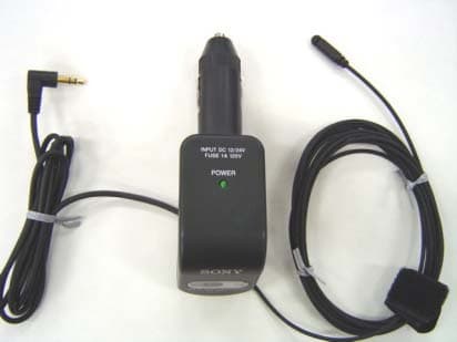
Click to zoom
Application Details
- Equipment Class
- DXX - Part 15 Low Power Communication Device Transmitter
- Date of Grant
- Jun 15, 2004
- Application Purpose
- Original Equipment
- Date of Application
- Jun 15, 2004
- Equipment Note
- Vehicle FM Transmitter
- Frequency Range
- 88.10000000 - 107.90000000
- Company
- Sony Group Corporation
- Country
- Japan
Documents & Files
Document Text
Text extracted from the exhibit documents filed with the FCC. Open a document above to read the original.
Users Manual
2-103-576-11(1) Operating Instructions FM Transmitter for Car Radio ©2004 Sony Corporation Printed in China DCC-FMT1 For customers who purchased this product in the USA Please register this product on line at http://www.sony.com/productregistration. Proper registration will enable us to send you periodic mailings about new products, services, and other important announcements. Registering your product will also allow us to contact you in the unlikely event that the product needs adjustment or modification. Thank you. WARNING To prevent fire or shock hazard, do not expose the unit to rain or moisture. To avoid electrical shock, do not open the cabinet. Refer servicing to qualified personnel only. Do not install the appliance in a confined space, such as a bookcase or built-in cabinet. To prevent fire or shock hazard, do not place objects filled with liquids, such as vases, on the apparatus. You are cautioned that any changes or modifications not expressly approved in this manual could void your authority to operate this equipment. Note This device complies with Part 15 of the FCC rules. Operation is subject to the following two conditions: (1)this device may not cause harmful interference, and (2)this device must accept any interference received, including interference that may cause undesired operation. Features With this unit, you can enjoy listening to audio played on portable audio devices through a car FM radio. Music from portable devices such as a MD, CD, or Network Walkman, etc., is transmitted to the car’s FM radio via FM radio waves. Stable clear sound • Using the flexible transmitting antenna, it is possible to transmit a stable FM radio wave in any kind of car. • Digital frequency selection, rather than analog, assures a more stable and clear transmission. Easy operation with the frequency select dial Select from 12 FM radio frequencies (channels) to transmit. No dry batteries This unit connects to a 12V or 24V DC car battery (cigarette lighter socket), available in many types of cars and trucks. “Walkman” and “WALKMAN” are registered trademarks of Sony Corporation. Precautions • Do not attempt to connect this unit, or to operate this unit, a portable audio device, or a car radio while driving or waiting at a traffic signal. Park in a safe place first. • Unplug this unit from the cigarette lighter socket whenever the engine of the car is not running. Depending on the car type, even if the ignition key is off, the power supply may not turn off automatically. In this case, this may cause unnecessary car battery consumption. • When not in use, unplug this unit from the cigarette lighter socket and store in a safe place where it will not interfere with your driving or become entangled in parts of the car interior (seat, door, etc.). • Be sure to fully secure the portable audio device connected to the unit to avoid moving when braking. • Route the antenna cable or signal cable properly so that they will not interfere with your driving or become entangled in parts of the car interior (seat, door, etc.). • Never yank or pull the antenna cable or signal cable. This may cause malfunctions or wire breaks. • Do not drop or hit the unit. This may cause malfunctions. Install the unit 1Rotate the frequency select dial to select the same frequency that you set on the car radio. The selected frequency appears in the frequency display window. The mark appears at the transition point between a low frequency band (88.1MHz~88.9MHz) and a high frequency band (106.7MHz~107.9MHz). See the mark as a borderline for high frequency and low frequency. 2Connect the stereo mini plug to the LINE OUT jack on the portable audio device. If there is no LINE OUT jack on the portable audio device, connect it to the headphone jack. How to use the INPUT LEVEL switch HIGH: Use HIGH level for general use. LOW: If you connect to the headphone jack on the portable audio device and the sound level is still low even if the volume is turned up, use LOW level. 3Insert this unit into the cigarette lighter socket. 4Start playback on the portable audio device. 5Place the antenna cable inside the car to improve the reception. Notes • Place the antenna cable close to the car antenna if the reception is poor. This may help to improve the reception. • Place the antenna cable in a manner that does not disturb your driving and is out of the reach of children. • Route the cables so that they do not interfere with your driving. • Distortion or jamming may be due to external interference, depending on the area. If reception is affected, try selecting another better frequency. • For details about the car radio antenna, refer to the car operating instructions. • Place this unit in a manner that will not hinder the airbag function in an emergency. <Example of antenna cable positioning when the car radio antenna is at the front of the car> <Example of antenna cable positioning when the car radio antenna is at the back of the car> These are just sample cases. Adjust the antenna for best reception, depending on your car. 3 2 Portable audio device to a cigarette lighter socket Notes • Do not attempt to connect this unit, or to operate this unit, a portable audio device, or a car radio while driving or waiting at a traffic signal. Park in a safe place first. • Plug securely into the cigarette lighter socket. Notes on listening to CDs or MDs on car radio • If you connect this unit to the headphone jack on a portable audio device, cancel the bass boost function and the equalizer function. For details about these settings, refer to the operating instructions of the portable audio device. • If you connect this unit to the headphone jack on the portable audio device, set the volume control of the portable audio device as high as possible but not so high that the audio signal becomes distorted. Hint If you connect the unit to the headphone jack on the portable audio device and the sound is low even if the volume is turned up, change the INPUT LEVEL…
Text truncated - open the document above for the full version.
External Photos
External Photos 1 Car FM Stereo Transmitter: DCC-FMT1 Connecting cable to Portable Audio Product Antenna Cable Power lump Frequency display window External Photos 2 Car FM Stereo Transmitter: DCC-FMT1 To a cigarette lighter socket Frequency select dial Frequency select dial External Photos 3 Car FM Stereo Transmitter: DCC-FMT1 Frequency select dial Antenna Cable Nameplate Connecting cable to Portable Audio Product Nameplate Input level switch
ID Label/Location Info
Nameplate Label including FCC ID Car FM Stereo Transmitter: DCC-FMT1 Nameplate Label Label material: Polyester film Bonding: Adhesive FCC ID:AK8DCCFMT1
Internal Photos
Internal Photos 1 Car FM Stereo Transmitter: DCC-FMT1 DCC Circuit Board (A-side) TX Circuit Board Connecting cable to Portable Audio Product Antenna Cable TX Circuit Board (A-side) Frequency select dial Internal Photos 2 Car FM Stereo Transmitter: DCC-FMT1 TX Circuit Board (A-side) SW1 X1 Antenna Cable Antenna Cable DCC Circuit Board (B-side) TX Circuit Board (B-side) IC3 Connecting cable to Portable Audio Product Internal Photos 3 Car FM Stereo Transmitter: DCC-FMT1 Antenna Cable IC3 CT1 TX Circuit Board (B-side) L1 D1
Test Report
Test report No. : 24JE0129-HO Page : 2 of 21 Issued date : June 11, 2004 FCC ID : AK8DCCFMT1 Revised date : June 14, 2004 UL Apex Co., Ltd. Head Office EMC Lab. 4383-326 Asama-cho, Ise-shi, Mie-ken 516-0021 JAPAN Telephone : +81 596 24 8116 Facsimile : +81 596 24 8124 MF060b(10.04.03) CONTENTS PAGE SECTION 1: Client information .................................................................................................................... 3 SECTION 2: Equipment under test (E.U.T.)................................................................................................ 3 SECTION 3: Test specification, procedures & results ................................................................................ 4 SECTION 4: Operation of E.U.T. during testing ......................................................................................... 6 SECTION 5: 200kHz Band Width and 20 dB Band Width......................................................................... 7 SECTION 6: Emissions from the Intentional radiator and Spurious Emissions ...................................... 8 APPENDIX 1: Photographs of test setup ...................................................................................................... 9 Spurious Emissions .................................................................................................................................................... 9 Worst Case Position (Z-axis:Horizontal / Z-axis:Vertical) ................................................................................... 10 APPENDIX 2:Test instruments .................................................................................................................... 11 APPENDIX 3: Data of EMI test.................................................................................................................... 12 200kHz Band Width................................................................................................................................................. 12 20dB Band Width ..................................................................................................................................................... 14 Emissions from the Intentional radiators .............................................................................................................. 16 Spurious Emissions .................................................................................................................................................. 18 Spurious Emissions(Band Edge) ............................................................................................................................. 21 Test report No. : 24JE0129-HO Page : 3 of 21 Issued date : June 11, 2004 FCC ID : AK8DCCFMT1 Revised date : June 14, 2004 UL Apex Co., Ltd. Head Office EMC Lab. 4383-326 Asama-cho, Ise-shi, Mie-ken 516-0021 JAPAN Telephone : +81 596 24 8116 Facsimile : +81 596 24 8124 MF060b(10.04.03) SECTION 1: Client information Company Name : Sony Corporation Brand name : SONY Address : Shinagawa INTERCITY C Tower, 2-15-3 Konan Minato-ku, Tokyo, 108-6201 Japan Telephone Number : +81-03-5769-5640 Facsimile Number : +81-03-5769-5962 Contact Person : Kikuo Murata SECTION 2: Equipment under test (E.U.T.) 2.1 Identification of E.U.T. Type of Equipment : Car FM Stereo Transmitter Model No. : DCC-FMT1 Serial No. : 00000006 Rating : DC12/24V ( Test was taken under worse case DC12V) The carrier level for DC 12V is 3 dB higher than the one for DC 24V. Country of Manufacture : China Receipt Date of Sample : May 27, 2004 Condition of EUT : Engineering prototype (Not for Sale: This sample is equivalent to mass-produced items.) 2.2 Product Description Model No: DCC-FMT1(referred to as the EUT in this report) is the Car FM Stereo Transmitter. Equipment Type : Transmitter Frequency of operation : 88.1-107.9MHz (1ch: 88.1, 2ch: 88.3, 3ch: 88.5, 4ch: 88.7, 5ch: 88.9, 6ch: 106.9, 8ch: 107.1, 9ch: 107.3, 10ch: 107.5, 11ch: 107.7, 12ch: 107.9) Type of modulation : FM Bandwidth & Channel spacing : 200kHz & 0.2MHz Power control : No Mode of operation : Simplex Antenna Type : Integral (Cable) Method of Frequency Generation : LC Operating voltage (inner) : DC 12/24 V FCC 15.31 (e) This EUT provides stable voltage(DC5V) to the radio part constantly. Therefore, this EUT complies with the requirement. FCC Part 15.203 Antenna requirement The antenna is not removable from EUT. Therefore, the equipment complies with the antenna requirement of Section 15.203. Test report No. : 24JE0129-HO Page : 4 of 21 Issued date : June 11, 2004 FCC ID : AK8DCCFMT1 Revised date : June 14, 2004 UL Apex Co., Ltd. Head Office EMC Lab. 4383-326 Asama-cho, Ise-shi, Mie-ken 516-0021 JAPAN Telephone : +81 596 24 8116 Facsimile : +81 596 24 8124 MF060b(10.04.03) SECTION 3: Test specification, procedures & results 3.1 Test Specification Test Specification : FCC Part15 Subpart C : 2003 Title : FCC 47CFR Part15 Radio Frequency Device Subpart C Intentional Radiators Section 15.239 Operation in the band 88-108MHz : 2003 3.2 Procedures and results No. Item Test Procedure Specification Deviation Worst margin Results 1 200kHz Band Width FCC Part 2 Section 2.1049 Section 15.239(a) N/A 126.8kHz 106.7MHz Vertical Complied 2 Emissions from the Intentional radiators FCC Part 2 Section 2.1046 Section 15.239(b) N/A 0.1dB 106.700MHz 107.900MHz AV Complied 3 Spurious Emissions FCC Part 2 Section 2.1053 Section 15.239 (c) N/A 6.8dB 106.800MHz and 108.000MHz QP Complied 4 A custom built telemetry Intentional radiator - Section 15.239(d) N/A *1) N/A N/A 5 20dB Bandwidth ANSI C63.4:2003 Section 15.215(c) N/A N/A Complied *1) This test is not applicable since this EUT is not the ordered and produced equipment for the remote measurement used in the educational organization. Note: UL Apex’s EMI Work Procedures No. QPM05 *These tests were performed without any deviations from test procedure except for additions or exclusions. 3.3 Confirmation UL Apex Co., Ltd…
Text truncated - open the document above for the full version.
Test Setup Photos
Test report No. : 24JE0129-HO Page : 9 of 21 Issued date : June 11, 2004 FCC ID : AK8DCCFMT1 Revised date : June 14, 2004 UL Apex Co., Ltd. Head Office EMC Lab. 4383-326 Asama-cho, Ise-shi, Mie-ken 516-0021 JAPAN Telephone : +81 596 24 8116 Facsimile : +81 596 24 8124 MF060b(10.04.03) APPENDIX 1: Photographs of test setup Spurious Emissions Front Rear Test report No. : 24JE0129-HO Page : 10 of 21 Issued date : June 11, 2004 FCC ID : AK8DCCFMT1 Revised date : June 14, 2004 UL Apex Co., Ltd. Head Office EMC Lab. 4383-326 Asama-cho, Ise-shi, Mie-ken 516-0021 JAPAN Telephone : +81 596 24 8116 Facsimile : +81 596 24 8124 MF060b(10.04.03) Worst Case Position (Z-axis:Horizontal / Z-axis:Vertical) X-axis Y-axis Z-axis
Contact Information
Applicant
Kazuyuki Hori(Chief EMC/RF Compliance Specialist)
Technical Contact
Non-Technical Contact
UL Apex Co., Ltd.Keijiro Kumagai
[email protected]81-596-24-8116
Test Firm
UL Apex Co., Ltd.Tetsuya Hashimoto
Technical Specifications
| # | Rule Parts | Frequency Range | Power Output |
|---|---|---|---|
| 1 | 15C | 88.1 MHz - 107.9 MHz | - |
Other Applications from Sony Group Corporation
AK8WW81782
Aug 21, 2026Radio Equipment
Equipment Class
DSS - Part 15 Spread Spectrum TransmitterAK8CFIZCP2
Aug 03, 2026Wireless Controller
Equipment Class
DSS - Part 15 Spread Spectrum TransmitterAK8OEV321MUH
Apr 14, 2026LCD Monitor
Equipment Class
JAD - Part 15 Class A Digital DeviceAK8OEV431MUH
Apr 14, 2026LCD Monitor
Equipment Class
JAD - Part 15 Class A Digital DeviceAK8OEV271MUH
Apr 14, 2026LCD Monitor
Equipment Class
JAD - Part 15 Class A Digital Device