AK8DCRIP220Digital Video Camera Recorder
Sony Group Corporation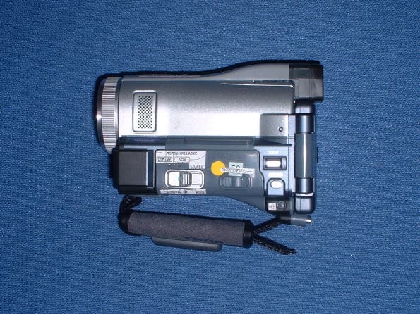
Click to zoom
Application Details
- Equipment Class
- DSS - Part 15 Spread Spectrum Transmitter
- Date of Grant
- Jul 31, 2002
- Application Purpose
- Original Equipment
- Date of Application
- Jul 31, 2002
- Equipment Note
- Digital Video Camera Recorder
- Frequency Range
- 2402.00000000 - 2480.00000000
- Company
- Sony Group Corporation
- Country
- Japan
Documents & Files
Document Text
Text extracted from the exhibit documents filed with the FCC. Open a document above to read the original.
Cover Letter(s)
American Telecommunications Certification Body Inc. 6731 Whittier Ave, McLean, VA 22101 July 26, 2002 RE: FCC ID: AK8DCRIP220 Attention: Kanako Sanda / Hiroka Umeyama I have a few comments on this Application. 1 While I can open the documents, the FCC is not capable of opening pdf documents with Asian fonts. Please remove all Asian and or Japanese fonts form the following documents and provide them to ATCB: Block Diagram (confidential_BlockDiagram.PDF), Test report (22IE0025-HO-2_FCC15C_.pdf, 22IE0025-HO-2(FCC15C)-2(data)a.pdf) and Test Setup Photos (Test Setup Photo.pdf). 2 While the device is compliant to conducted limits of the new FCC rules, the calculation of the limit appears to be off by several db. The linear interpolation is basically an y=mx+b evaluation. With 150kHz at 66dBuV (1995.2uV) and 500kHz at 56 dBuV (631uV) the value at 259.7kHz should be approximately 63.9dBuV (1567.5uV). The value at 389.6kHz should be approximately 60.5dBuv. As I stated, the device still appears to be compliant, but the report should reflect the correct limit values. Please explain how you derived at the limits in your report. 3 In some instances Bluetooth devices can have larger than 1mHz bandwidths in acquisition (inquiry) mode. Please verify that the device is compliant to the bandwidth requirements for frequency hopping devices in acquisition mode. 4 The 731 form states the power as 0.000026W (2.6mW). The reports however shows the conducted antenna power measurement to be 0.00000062W (0.62mW). An FCC grant contains the actual power measured, not power listed in brochures or technical documentation. The grant therefore will have a power rating of 0.00000062W (0.62mW). If you desire to have the 2.6mW rating on the grant you will have to retest a device that outputs power at this level. Please advice is you wish to retest at a higher level or if you wish to have the grant specify the 0.62mW measured power. If the higher power is desired, please provide a report with testing to show compliance of 15.247 at this higher power. 5 On page 45 of the report you list a ‘radiated’ power limit of 1W (1000mW). Please note that the 1W is an antenna conducted limit, not a radiated limit. Since you have provided conducted antenna measurements there is no need for Radiated Power measurements. If, however, you wish to include this table (page 45) then you must use the accepted procedure for calculating the Power. This is found in the FCC FHSS test procedure in DA000705. In order to calculate this values, you must use the formula P = (Ed) 2 /30G. Remember that G (gain of the antenna) must be the actual gain of the device antenna not an assumed gain of isotropic or dipole. Please correct the values in the table to show correct comparison to the 15.247 power limits. 6 Please note that the restricted band limit for 135MHz is the limit specified in 15.209. This limit is 150uV/m or 43.5dBuV not 40dBuV as stated in the report. While the device is still compliant, the report should be accurate with the correct limits. Please correct to show the correct limits for restricted band. Dennis Ward mailto:[email protected] The items indicated above must be submitted before processing can continue on the above referenced application. Failure to provide the requested information may result in application termination. Correspondence should be considered part of the permanent submission and may be viewed from the Internet after a Grant of Equipment Authorization is issued. l Page 2July 26, 2002 Please do not respond to this correspondence using the email reply button. In order for your response to be processed expeditiously, you must submit your documents through the AmericanTCB.com website. Also, please note that partial responses increase processing time and should not be submitted. Any questions about the content of this correspondence should be directed to the sender.
Cover Letter(s)
A- PEX INTERNATIONAL CO., LTD. •EMC HEAD OFFICE DIVISION•4383-326 Asama-cho, Ise-shi, Mie-ken 516-0021 Japan TEL:0596-24-8116/FAX:0596-24-8124 August 1, 2002 Re : Sony Corporation FCC ID : AK8DCRIP220 Dear Mr. Dennis Ward Please find the following replies to your comments dated July 27, 2002; 1) Please refer to submitted PDF files “Revised Block Diagram”, “22IE0025-HO-2_FCC15C_.(Revised)pdf” , “Revised 22IE0025-HO-2(FCC15C)-2(data)a” and “Revised Test Setup Photo”. 2) This interpolation is decreased with the logarithm of the frequency, not linear. So, this value is calculated by 66-10{log (x/0.15)/log (0.5/0.15)}. Please, calculate again. 3) Frequency is changing all the time in acquisition (inquiry) mode, therefore, it is impossible to measure 1MHz bandwidth by specified frequency. Please kindly inform us how should we measure the value in detail? 4) Please refer to submitted PDF file “Revised Form 731”. 5) Actual value for Antenna Gain of the device is 0.25dBi. We calculated by Numeric Antenna Gain (1.06), do you think it is OK? 6) Please refer to submitted PDF files “22IE0025-HO-2_FCC15C_.(Revised)pdf” and “Revised 22IE0025-HO- 2(FCC15C)-2(data)a”. Keijiro Kumagai A-Pex Int ernational Co., Ltd.
External Photos
SONY CORPORATION FCC ID:AK8DCRIP220 Back Front SONY CORPORATION FCC ID:AK8DCRIP220 Right Left (No.1) SONY CORPORATION FCC ID:AK8DCRIP220 Left (No.2) SONY CORPORATION FCC ID:AK8DCRIP220 Bottom
Internal Photos
SONY CORPORATION FCC ID:AK8DCRIP220 Cover opened Cover opened (No.2) SONY CORPORATION FCC ID:AK8DCRIP220 Antenna and Circuit board (connected) Antenna and Circuit board (connected) No.2 SONY CORPORATION FCC ID:AK8DCRIP220 Circuit board with antenna cable Antenna and circuit board (front) SONY CORPORATION FCC ID:AK8DCRIP220 Antenna and Circuit board (back) SONY CORPORATION FCC ID:AK8DCRIP220 Circuit board with sheild (front) Circuit board (back)
Operational Description
Operation Description 1.Sending The sending base-band 1MBps signal is divided two signals, I and Q. DAC and filter remove unnecessary high frequency from signals. Besides, the signal at 2.4GHz after passing the first local oscillator goes through phase converter. And it is transformed phase difference-90°signal, goes into multiplication unit of I and Q. At Addition unit, GFSK-modulation occurs by adding I and Q. The modulated carrier waves go through balanced-unbalanced unit after amplification at amp. And the signal is sent after the harmonic waves from local oscillator and power amp distortion are removed from the signal by band-pass-filter. 2.Receiving At first, the disturbance electric waves outside of used band are removed from the input carrier waves by band-pass-filter. After going through balanced-unbalanced unit, the receiving signal is amplified by low-noise-amp and go into mix unit. And the signal is transformed the middle frequency at 1.5MHz after it is multiplied 1.5MHz lower signal than the carrier waves of 2.4GHz-band that double the frequency from the local oscillator of 1.2GHz- band. The middle frequency signal is removed disturbance electric waves inside used band by passing inside of band-pass-filter. After the signal at 1.5MHz from the second local oscillator is multiplied at multiplication unit, Q and I are added at addition unit. And added signal, Q, and I are demodulated to base-band signal after removing unnecessary high frequency by low-pass-filter. 3.Antenna location There is an antenna inside the video camera recorder. It is impossible to remove the antenna and to change this.
RF Exposure Info
RF Exposure Statement No. : 22IE0025-HO-2 Applicant: SONY Corporation Type of Equipment: Digital Video Camera Recorder Model No.: DCR-IP220 FCC ID: AK8DCRIP220 A-Pex International Co., Ltd. EMC Head Office 4383-328 Asama-cho, Ise-shi, Mie-ken 516-0021 JAPAN Telephone:int +81 596 24 8116 Facsimile: int +81 596 24 8124 Page 1 FCC Radiation Exposure Statement: SONY Corporation Model : DCR-IP220 complies with FCC radiation exposure requirement specified in the FCC Rules 15.247(b)(4). Notice in Installation Manual CAUTION This equipment complies with FCC radiation exposure limits set forth for an uncontrolled environment. To comply with FCC RF exposure requirements, the following antenna installation and device operating configurations must be satisfied: the antenna has been installed by the manufacturer and no change can be made . This device and its antenna(s) must not be co-located or operating in conjunction with any other antenna or transmitter. RF Exposure Calculations: The following information provides the minimum separation distance for the highest gain antenna provided with the “DCR-IP220” as calculated from FCC OET 65 Appendix B, Table (B) Limits for General Population / Uncontrolled Exposure. This calculation is based on the highest EIRP possible from the system, considering maximum power and antenna gain, and considering a 1.0m W/cm^2 uncontrolled exposure limit. The Friis formula used was: S = (P * G) / (4* ð * r^2) or r = (P * G) / (4 * ð* S) Where S = 1.0 mW/cm^2 for 2400 MHz P = 0.62mW (Maximum Conducted Power) G = 1.06 (Antenna gain : Converted absolute value) r = Minimum safe distance from antenna (cm) For: DCR-IP220 r = 0.23cm
Test Report
Test report No. : 22IE0025-HO-2 Page: 2 of 82 Issued date: June 24 , 2002 FCC ID: AK8DCRIP220 A-PEX International Co., Ltd. EMC Head Office Division. 4383-326 Asama-cho, Ise-shi, Mie-ken 516-0021 JAPAN Telephone: +81 596 24 8116 Facsimile: +81 596 24 8124 CONTENTS PAGE SECTION 1: Client information 3 SECTION 2: Equipment under test (E.U.T.)3 SECTION 3: Test specification, procedures and results 5 SECTION 4: Operation of E.U.T. during testing7 SECTION 5: Conducted emission, Section 15.20710 SECTION 6: Carrier Frequency Separation, Section 15.247(a)(1) 10 SECTION 7: 20dB Bandwidth, Section 15.247(a)(1)(ii) 11 SECTION 8: Number of Hopping Frequency, Section 15.247(a)(1)(ii) 11 SECTION 9: Dwell time, Section 15.247(a)(1)(ii) 11 SECTION 10: Maximum Peak Output Power, Section 15.247(b)(1) 12 SECTION 11: Band Edge compliance, Section 15.247(c) 12 SECTION 12: Spurious Emission, Section 15.247(c) 13 APPENDIX 1: Photographs of test setup 14 APPENDIX 2: Data of EMI test 14 APPENDIX 3: Test instruments 14 Test report No. : 22IE0025-HO-2 Page: 3 of 82 Issued date: June 24 , 2002 FCC ID: AK8DCRIP220 A-PEX International Co., Ltd. EMC Head Office Division. 4383-326 Asama-cho, Ise-shi, Mie-ken 516-0021 JAPAN Telephone: +81 596 24 8116 Facsimile: +81 596 24 8124 SECTION 1: Client information Company name: SONY Corporation Address : 6-7-35 Kitashinagawa, Shinagawa-ku, Tokyo 141- 0001 Japan Telephone Number: +81-3-5769-5643 Facsimile Number: +81-3-5769-5963 Contact Person: Susumu Ishiwata SECTION 2: Equipment under test (E.U.T.) 2.1Identification of E.U.T. Type of Equipment: Digital Video Camera Recorder Model No.: DCR-IP220 Serial No.: 95 and 96 Rating: DC 7.2V AC Adaptor AC 120V/60Hz Country of Manufacture: Japan Receipt Date of Sample : June 3, 2002 Condition of EUT: Engineering prototype Test report No. : 22IE0025-HO-2 Page: 4 of 82 Issued date: June 24 , 2002 FCC ID: AK8DCRIP220 A-PEX International Co., Ltd. EMC Head Office Division. 4383-326 Asama-cho, Ise-shi, Mie-ken 516-0021 JAPAN Telephone: +81 596 24 8116 Facsimile: +81 596 24 8124 2.2Product Description Model: DCR-IP220 which was referred to as the EUT in this report is the Digital Video Camera Recorder. The specification is as following; Equipment Type: Transceiver Clock frequency used in EUT: 67.5MHz Frequency characteristics: from 2402MHz to 2480MHz Number of Channel/ Channel spacing: 79 channels/ 1MHz Modulation: FSK (Frequency Shift Keying) and FHSS (Frequency Hopping Spread Spectrum) Antenna Type: Wire-coupled Mono-pole Antenna (Integral) Antenna Gain : 0.25 dBi ITU code: 79M4F1D *FCC Part 15.31 (e) The host device DCR-IP220 provide the stable power supply (DC: 7.2V), and the Digital Video Camera Recorder complies power supply regulation. *FCC Part 15.203 Antenna requirement Digital Video Camera Recorder and its antenna comply with this requirement since they are built in host device DCR- IP220 when they are put up for sale and they are used with a particular antenna connector. Test report No. : 22IE0025-HO-2 Page: 6 of 82 Issued date: June 24 , 2002 FCC ID: AK8DCRIP220 A-PEX International Co., Ltd. EMC Head Office Division. 4383-326 Asama-cho, Ise-shi, Mie-ken 516-0021 JAPAN Telephone: +81 596 24 8116 Facsimile: +81 596 24 8124 3.5Uncertainty Conducted Emission Test The measurement uncertainty (with a 95% confidence level) for this test was ±1.3dB. □ The data listed in this test report may exceed the test limit because it does not have enough margin. ■ The data listed in this test report has enough margin, more than the site margin. Peak Output Power (Radiated) and Spurious Emission Test The measurement uncertainty (with a 95% confidence level) for this test using Biconical antenna is ±4.5dB. The measurement uncertainty (with a 95% confidence level) for this test using Logperiodic antenna is ±5.2dB. The measurement uncertainty (with a 95% confidence level) for this test using Horn antenna is ±6.6dB. ■ The data listed in this test report may exceed the test limit because it does not have enough margin. □ The data listed in this test report has enough margin. Carrier Frequency Separation, 20dB Bandwidth, Number of Hopping Frequency, Dwell Time, Peak Output Power (Conducted) and Band Edge Test The measurement uncertainty (with a 95% confidence level) for this test was ±3.0dB. □ The data listed in this test report may exceed the test limit because it does not have enough margin. ■ The data listed in this test report has enough margin. 3.6 Test Location A-PEX International Co., Ltd. EMC Head Office Division. No.1 and No.2 semi Anechoic chamber and No.3 Measurement room. 4383-326 Asama-cho, Ise-shi, Mie-ken 516-0021 JAPAN Telephone: +81 596 24 8116 Facsimile: +81 596 24 8124 This site has been fully described in a report submitted to FCC office. No. 1 site listed on February, 2002 and No. 2 site on June. (Registration number: No. 1: 313583, No.2: 846015 Industry Canada: No.1: IC4247, No2. :IC4247- 2.) *NVLAP Lab. code: 200572-0 3.7Test set up, Data of EMI and Test instruments Refer to APPENDIX 1 to 3. Test report No. : 22IE0025-HO-2 Page: 7 of 82 Issued date: June 24 , 2002 FCC ID: AK8DCRIP220 A-PEX International Co., Ltd. EMC Head Office Division. 4383-326 Asama-cho, Ise-shi, Mie-ken 516-0021 JAPAN Telephone: +81 596 24 8116 Facsimile: +81 596 24 8124 SECTION 4: Operation of E.U.T. during testing 4.1Operating Modes The EUT exercise program used during radiated and conducted testing was designed to exercise the various system components in a manner similar to typical use. The operating mode/system was as follows: Operation mode : 1. Transmitting mode (2402MHz) 2. Transmitting mode (2441MHz) 3. Transmitting mode (2480MHz) 4. Transmitting (Hopping on) 5. Inquiry 6. Loopback mode Justification: The system was configured in typical fashion (as a customer would normally use it) for testing. 4.2 Configuration and peripherals [Conducted Emission, Peak Output Power (Radiated) and Spurious Emission Test ] AC 120V/60Hz AC 120V/60Hz 8 9 H I A EUT B C D E …
Text truncated - open the document above for the full version.
Test Report
Spurious Emission(Conducted) :Tx(2441MHz) 78 Spurious Emission(Conducted) :Tx(2441MHz) Spurious Emission(Conducted) :Tx(2441MHz) 79 Spurious Emission(Conducted) :Tx(2441MHz) Spurious Emission(Conducted) :Tx(2480MHz) 80 Spurious Emission(Conducted) :Tx(2480MHz) Spurious Emission(Conducted) :Tx(2480MHz) 81 Spurious Emission(Conducted) :Tx(2480MHz)
Test Report
A-PEX INTERNATIONAL CO., LTD. EMC HEAD OFFICE DIVISION 4383-326 Asama-cho, Ise-shi, Mie-ken 516-0021 Japan TEL:0596-24-8116/FAX:0596-24-8124 Dear Mr. Dennis Ward Thank you for your kind comments and advice. Following statements are reply to your comments for FCC ID: AK8DCRIP220. Please verify. 1. Peak output power (radiated) We would like to delete pages 45 to 48 of measurement data with regard to “Peak output power (radiated)” according to your advice on July 27 e-mail, because we have already submitted “Peak output power (conducted)” in pages 42 to 44 of the “Test Report“. Please insert attached PDF “Replacements for Test Report Page 45-48.pdf” in place of pages 45 to 48. 2. Conducted noise voltage We understood what you said. So, we added a note in the “Data of conduction test” of page 18. The note is: “The above from 0.15kHz to 0.45kHz were reference data”. Please find attached PDF “Replacement for Test Report Page18.pdf”. 3. Bandwidth in acquisition mode: We understood what FCC conceived. However, hopping-off mode during acquisition could not be provided in this equipment. Therefore, as seen in data (both lower and upper data) of page 31 in “Test Report”, if the hopping-off mode cannot be achieved, 20dB bandwidth cannot be measured. Please find attached PDF “Replacements for Test Report Page26-28.pdf”. Please advise the FCC measurement procedure. We believe we have already answered for all your comments. Keijiro Kumagai A-Pex International Co., Ltd.
Test Setup Photos
Test report No. : 22IE0025-HO-2 Page: 15 of 82 Issued date: June 24 , 2002 FCC ID: AK8DCRIP220 A-PEX International Co., Ltd. EMC Head Office Division. 4383-326 Asama-cho, Ise-shi, Mie-ken 516-0021 JAPAN Telephone: +81 596 24 8116 Facsimile: +81 596 24 8124 APPENDIX 1: Photographs of test setup Conducted emission Peak Output Power (Radiated) and Spurious Emission Test Test report No. : 22IE0025-HO-2 Page: 16 of 82 Issued date: June 24 , 2002 FCC ID: AK8DCRIP220 A-PEX International Co., Ltd. EMC Head Office Division. 4383-326 Asama-cho, Ise-shi, Mie-ken 516-0021 JAPAN Telephone: +81 596 24 8116 Facsimile: +81 596 24 8124 Carrier Frequency Separation, 20dB Bandwidth, Number of Hopping Frequency, Dwell Time, Peak Output Power (Conducted) and Band Edge Test Test report No. : 22IE0025-HO-2 Page: 17 of 82 Issued date: June 24 , 2002 FCC ID: AK8DCRIP220 A-PEX International Co., Ltd. EMC Head Office Division. 4383-326 Asama-cho, Ise-shi, Mie-ken 516-0021 JAPAN Telephone: +81 596 24 8116 Facsimile: +81 596 24 8124
Contact Information
Applicant
Kazuyuki Hori(Chief EMC/RF Compliance Specialist)
Technical Contact
A-Pex International Co., LtdHiroka Umeyama
[email protected]+81-596-24-8116
4383-326 Asama-cho · Ise-shi, Mie-ken · Japan
Non-Technical Contact
A-Pex International Co., Ltd.Kanako Sanda
[email protected]+81-596-24-8116
Test Firm
UL Japan, IncMitsuru Fujimura
Technical Specifications
| # | Rule Parts | Frequency Range | Power Output |
|---|---|---|---|
| 1 | 15C | 2.40 GHz - 2.48 GHz | 620.00 µW |
Other Applications from Sony Group Corporation
AK8WW81782
Aug 21, 2026Radio Equipment
Equipment Class
DSS - Part 15 Spread Spectrum TransmitterAK8CFIZCP2
Aug 03, 2026Wireless Controller
Equipment Class
DSS - Part 15 Spread Spectrum TransmitterAK8OEV321MUH
Apr 14, 2026LCD Monitor
Equipment Class
JAD - Part 15 Class A Digital DeviceAK8OEV431MUH
Apr 14, 2026LCD Monitor
Equipment Class
JAD - Part 15 Class A Digital DeviceAK8OEV271MUH
Apr 14, 2026LCD Monitor
Equipment Class
JAD - Part 15 Class A Digital Device