AK8DCRPC120Digital Video Camera Recorder - Bluetooth
Sony Group Corporation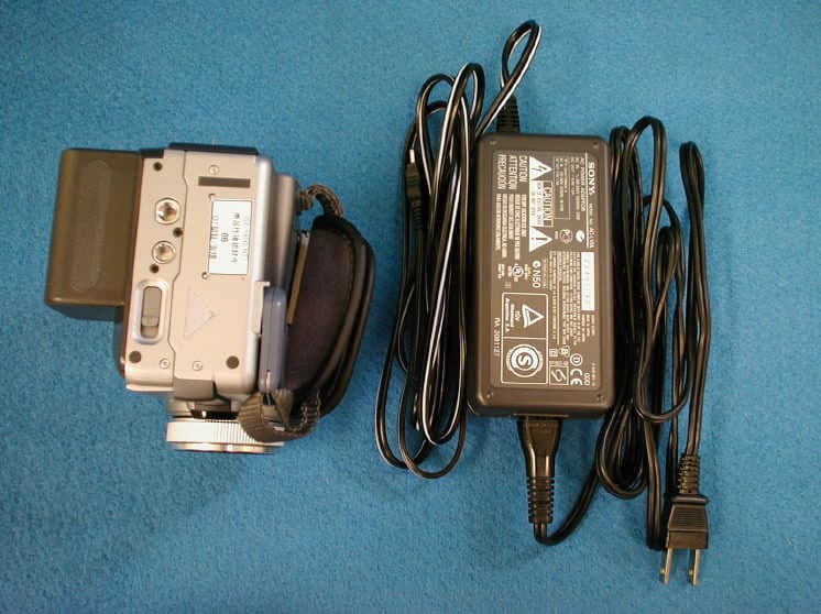
Click to zoom
Application Details
- Equipment Class
- DSS - Part 15 Spread Spectrum Transmitter
- Date of Grant
- Sep 09, 2001
- Application Purpose
- Original Equipment
- Date of Application
- Sep 09, 2001
- Equipment Note
- Digital Video Camera Recorder - Bluetooth
- Frequency Range
- 2402.00000000 - 2480.00000000
- Company
- Sony Group Corporation
- Country
- Japan
Documents & Files
Document Text
Text extracted from the exhibit documents filed with the FCC. Open a document above to read the original.
Users Manual
3-069-935-11 (1) DCR-IP7/IP7BT/ PC120/PC120BT Network Function Operating Instructions © 2001 Sony Corporation Registration code 2 On trademarks • ImageStation is the registered trademark of Sony Corporation. • “Memory Stick” and are the registered trademarks of Sony Corporation. • The BLUETOOTH trademarks are owned by their proprietor and used by Sony Corporation under license. • NetFront by Access Co., Ltd. is adopted for the Internet function of this product. NetFront is registered trademark of Access Co., Ltd in Japan. Copyright © 1996 – 2000 ACCESS CO., LTD. • Portions of the supplied software are based in part on the work of the Independent JPEG Group. All other product names mentioned herein may be the trademarks or registered trademarks of their respective companies. Furthermore, “™” and “®” are not mentioned in each case in this manual. No compensation for your recording Contents of the recording cannot be compensated if recording or playback of attached or downloaded files is not made due to a malfunction, storage media, etc. Precaution • Before using the network function, be sure to set up the clock of the camcorder. For details, refer to the operating instructions of the camcorder. If you use the network function without setting the clock, you may not send or receive e-mail, or view a Web page. • Do not remove the battery pack or disconnect the AC power adaptor while in NETWORK mode. The setup for the NETWORK mode may be lost. Also, exit the NETWORK mode when setting the POWER switch to OFF (CHG) or switching the mode. • We recommend that you make backup copies of the e-mail messages, the network preferences. These may be lost due to a memory corruption. As for the network preferences, write them down on paper. (Use “Setup memo” on page XX.) Also, these data may be lost when repairing the camcorder by services. • The network function is available only in the country or area where you purchased the camcorder. • The reset button cannot reset the network preferences. For customers in CANADA Operation is subject to the following two conditions: (1) this device may not cause interference, and (2) this device must accept any interference, including interference that may cause undesired operation of the device. To prevent radio interference to the licensed service, this device is intended to be operated indoors and away from windows to provide maximum shielding. Equipment that is installed outdoors is subject to licensing. 3 Table of contents 4 – Introduction – Network function on the camcorder The camcorder can access the Internet through your provider by a dial-up networking connection with a Bluetooth device, and view a Web page, send and receive e-mail with images attached to it. Bluetooth specification ver. 1.1 is adopted for the communication system of the camcorder, and Compatible Bluetooth profiles are “Generic Access Profile” and “Dial-up Networking Profiles.” Customer registration makes you use “Sony Style Connect” for setting network preferences easily and “An album on the Web” for providing a special photo album on the Internet for the user. The album on the Web uses the function of “ImageStation.” • Access the Internet easily You can view a Web page via the Internet. • Send/receive your e-mail You can send or receive e-mail anytime, and attach images to e- mail. Your camcorder To the InternetBluetooth device, such as the Modem Adaptor with Bluetooth function 5 • Making your album on the Web You can upload images to your album, and view or edit your album. • Easy network preferences (Sony Style Connect) Using “Sony Style Connect,” you can easily set the Internet and e-mail preferences. Once you make the DI customer registration, you can get your DI customer ID and password. Entering your DI customer ID, password, and telephone number of an access point, you can access the Internet right away. To use “Sony Style Connect,” the customer registration and sign-up with the recommended internet service provider (R-net) are required. Before using the network function, be sure to set up the clock of the camcorder. The clock is not set up at the default setting. You also have to set up the camcorder and the peripheral device, and make registrations (Customer registration, internet service provider sign-up, etc.) Network function on the camcorder 6 Network function on the camcorder Before using the network function Check that the procedure for using the network function following the flowchart below. When using all of the network function – An album on the Web, e-mail, browser ika mitei When using e-mail and browser of the network function ika mitei 7 Network function on the camcorder Required procedures list 8 Overview of the Bluetooth wireless technology What is the Bluetooth wireless technology? The Bluetooth wireless technology allows communication between various Bluetooth devices without using cables. Devices which can use this technology include PCs, computer peripheral devices, PDAs, and mobile phones. This omnidirectional communication system enables communication even if the Bluetooth devices is in a bag or there are obstacles between the devices. Also, the Bluetooth wireless technology has an advanced security, such as scramble frequency, data encryption. Authentication Authentication routine can block unspecified users’ access to this network. When making a communication with an unregistered Bluetooth device, register each other by entering a common pass key to each device, first. When connecting with a registered Bluetooth device, communication starts without entering the pass key. 9 Basic operations in the NETWORK mode This section describes basic control ways to operate the camcorder, which are used for the network operations. How to use the Network Menu To access the Network Menu, refer to the section “Accessing to the network” in the operating instructions supplied with your camcorder. <illustration> [a]: Send and receive e-mail. For details, see “Using e-mail” on p…
Text truncated - open the document above for the full version.
Users Manual
Explanation regarding the Model name of DCR-PC120 and DCR-PC120BT The DCR-PC120BT is a package model name which includes Digital video camera recorder unit (model name DCR-PC120) and supplied accessories. Although model name on instruction manual indicates DCR-PC120BT, model name of Digital video camera recorder unit itself is DCR-PC120. Above information is described on Page 10 of the Instruction manual, so please refer to it also.
Users Manual
3-070-602-11 (1) ©2001 Sony Corporation Operating Instructions Before operating the unit, please read this manual thoroughly, and retain it for future reference. Owner’s Record The model and serial numbers are located on the bottom. Record the serial number in the space provided below. Refer to these numbers whenever you call upon your Sony dealer regarding this product. DCR-PC115/PC120BT Digital Video Camera Recorder Model No. DCR-PCModel No. AC- Serial No.Serial No. SERIES TM DCR-PC120BT 2 Welcome! Congratulations on your purchase of this Sony Handycam. With your Handycam, you can capture life’s precious moments with superior picture and sound quality. Your Handycam is loaded with advanced features, but at the same time it is very easy to use. You will soon be producing home video that you can enjoy for years to come. WARNING To prevent fire or shock hazard, do not expose the unit to rain or moisture. CAUCTION The use of optical instruments with this product will increase eye hazard. As the laser beam used in this Handycam is harmful to eyes, do not attempt to disassemble the cabinet. Refer to servicing to qualified personnel only. This symbol is intended to alert the user to the presence of uninsulated “dangerous voltage” within the product’s enclosure that may be of sufficient magnitude to constitute a risk of electric shock to persons. This symbol is intended to alert the user to the presence of important operating and maintenance (servicing) instructions in the literature accompanying the appliance. For customers in the U.S.A. and CANADA CAUTION TO PREVENT ELECTRIC SHOCK, MATCH WIDE BLADE OF PLUG TO WIDE SLOT, FULLY INSERT. DISPOSAL OF LITHIUM ION BATTERY. LITHIUM ION BATTERY. DISPOSE OF PROPERLY. You can return your unwanted lithium ion batteries to your nearest Sony Service Center or Factory Service Center. Note:In some areas the disposal of lithium ion batteries in household or business trash may be prohibited. For the Sony Service Center nearest you call 1-800-222-SONY (United States only). For the Sony Factory Service Center nearest you call 416-499-SONY (Canada only). Caution:Do not handle damaged or leaking lithium ion battery. “Memory Stick” THIS DEVICE COMPLIES WITH PART 15 OF THE FCC RULES. OPERATION IS SUBJECT TO THE FOLLOWING TWO CONDITIONS: (1) THIS DEVICE MAY NOT CAUSE HARMFUL INTERFERENCE, AND (2) THIS DEVICE MUST ACCEPT ANY INTERFERENCE RECEIVED, INCLUDING INTERFERENCE THAT MAY CAUSE UNDESIRED OPERAION. THIS CLASS B DIGITAL APPARATUS COMPLIES WITH CANADIAN ICES-003. 3 For the customers in the U.S.A. If you have any questions about this product, you may call: Sony Customer Information Center 1-800-222- SONY (7669) The number below is for the FCC related matters only. Regulatory Information Declaration of Conformity Trade Name:SONY Model No.:DCR-PC120 Responsible Party:Sony Electronics Inc. Address:680 Kinderkamack Road, Oradell, NJ07649 U.S.A. Telephone No.:201-930-6972 This device complies with Part 15 of the FCC Rules. Operation is subject to the following two conditions: (1) This device may not cause harmful interference, and (2)this device must accept any interference received, including interference that may cause undesired operation. CAUTION You are cautioned that any changes or modifications not expressly approved in this manual could void your authority to operate this equipment. Note: This equipment has been tested and found to comply with the limits for a Class B digital device, pursuant to Part 15 of the FCC Rules. These limits are designed to provide reasonable protection against harmful interference in a residential installation. This equipment generates, uses, and can radiate radio frequency energy and, if not installed and used in accordance with the instructions, may cause harmful interference to radio communications. However, there is no guarantee that interference will not occur in a particular installation. If this equipment does cause harmful interference to radio or television reception, which can be determined by turning the equipment off and on, the user is encouraged to try to correct the interference by one or more of the following measures: — Reorient or relocate the receiving antenna. — Increase the separation between the equipment and receiver. — Connect the equipment into an outlet on a circuit different from that to which the receiver is connected. — Consult the dealer or an experienced radio/TV technician for help. The supplied interface cable must be used with the equipment in order to comply with the limits for a digital device pursuant to Subpart B of Part 15 of FCC Rules. 4 Taking moving or still images, and playing them back • Recording a moving picture on a tape (p. xx) • Recording a still image on a tape (p. xx) • Playing back a tape (p. xx) • Recording still images on “Memory Stick”s (p. xx) • Recording moving pictures on “Memory Stick”s (p. xx) • Viewing a still image recorded on “Memory Stick”s (p. xx) • Viewing a moving picture on “Memory Stick”s (p. xx) Capturing images on your computer • Using with an analog video unit and your computer (p. xx) • Viewing images recorded on “Memory Stick”s using the USB cable (p. xx) Accessing to the Internet via a Bluetooth equipped device (DCR-PC120BT only) Accessing the Internet, sending/receiving your e-mail, and using the album on the Web (Only in North America and Japan). For details, refer to the Network Operating Instructions supplied with your camcorder. (p. xx) Other uses Functions to adjust exposure in the recording mode • Back light (p. xx) • NightShot/Super NightShot (p. xx) • Recording images with the flash (p. xx, xx) • PROGRAM AE (p. xx) • Adjusting the exposure manually (p. xx) Functions to give images more impact • Digital zoom (p. xx) The default setting is set to OFF. (To zoom greater than 10×, select the digital zoom power in D ZOOM in the menu settings.) • Fader (p. xx) • Picture effect (p. xx) • Digital effect (p. xx) • Title (p. xx, xx) • MEMORY MIX (p. xx) Functions …
Text truncated - open the document above for the full version.
Users Manual
66 Using the A/V connecting cable You can dub or edit on the VCR connected to your camcorder using your camcorder as a player. Connect your camcorder to the VCR using the A/V connecting cable supplied with your camcorder. Before operation •Set DISPLAY to LCD in the menu settings. (The default setting is LCD.) •Press the following buttons to make the indicator disappear so that they will not be superimposed on the edited tape: –DISPLAY –DATA CODE on the Remote Commander –SEARCH MODE on the Remote Commander (1)Insert a blank tape (or a tape you want to record over) into the VCR, and insert the recorded tape into your camcorder. (2)Prepare the VCR for recording, then set the input selector to LINE. Connect the A/V connecting cable to AUDIO/VIDEO jack. Refer to the operating instructions of the VCR. (3)Set the POWER switch to VCR on your camcorder. (4)Play back the recorded tape on your camcorder. (5)Start recording on the VCR. Refer to the operating instructions of your VCR. When you have finished dubbing a tape Press x on both your camcorder and the VCR. You can edit on VCRs that support the following systems: 8 mm, Hi8, VHS, S-VHS, VHSC, S-VHSC, Betamax, ED Betamax, mini DV, DV, Digital8 If your VCR is a monaural type Connect the yellow plug of the A/V connecting cable to the video input jack and the white or the red plug to the audio input jack on the VCR or the TV. When the white plug is connected, the left channel audio is output, and when the red plug is connected, the right channel audio is output. — Editing — Dubbing a tape S VIDEO VIDEO AUDIO IN AUDIO/VIDEO S VIDEO : Signal flow 67 Editing If your VCR has an S video jack Pictures can be reprodeced more faithfully by using an S video cable (optional). With this connection, you do not need to connect the yellow (video) plug of the A/V connecting cable. Connect an S video cable (optional) to the S video jacks of both your camcorder and the VCR. This connection produces higher quality DV format pictures. Using the i.LINK cable (DV connecting cable) Simply connect the i.LINK cable (DV connecting cable) (optional) to DV jack of your camcorder and to DV IN of the DV products. With a digital-to-digital connection, video and audio signals are transmitted in digital form for high-quality editing. You cannot dub the titles, display indicators or the contents of cassette memory or letters on the “Memory Stick” index screen. Set the input selector on the VCR to the DV input position if the VCR is equipped with the input selector. (1)Insert a blank tape (or a tape you want to record over) into the VCR, and insert the recorded tape into your camcorder. (2)Prepare the VCR for recording. Set the input selector to LINE. Refer to the operating instructions of the VCR. (3)Set the POWER switch to VCR on your camcorder. (4)Play back the recorded tape on your camcorder. (5)Start recording on the VCR. Refer to the operating instructions of the VCR. When you have finished dubbing a tape Press x on both your camcorder and the VCR. You can connect one VCR only using the i.LINK cable (DV connecting cable) See page xxx for more information about i.LINK. Pictures processed by the picture effect, the digital effect or PB ZOOM function Pictures processed by the picture effect, the digital effect or PB ZOOM function are not output through the DV jack. If you record a playback pause picture with the DV jack The recorded picture becomes rough. And when you play back the picture using the other video equipment, the picture may jitter. Dubbing a tape DV DV DV IN (optional) : Signal flow 68 You can duplicate selected scenes (programs) for editing onto a tape without operating the VCR. Scenes can be selected by frame. You can set up to 20 programs. Your camcorder can dub on “Memory Stick”s. See p. xx for more information. Before operating the Digital program editing to a tape Step 1Connecting the VCR (p. xx). Step 2Setting the VCR for operation (p. xx, xx). Step 3Adjusting the synchronization of the VCR (p. xx). When you dub using the same VCR again, you can skip steps 2 and 3. Using the Digital program editing function Operation 1Making the program (p. xx). Operation 2Performing the program (dubbing a tape) (p. xx). Notes •When you connect with an i.LINK cable (DV connecting cable), you may not be able to operate the dubbing function correctly, depending on the VCR. Set CONTROL to IR in the menu settings of your camcorder. •When editing digital video to a tape, the operation signals cannot be sent with LANC. Step 1: Connecting the VCR You can connect both an A/V connecting cable and an i.LINK cable (DV connecting cable). When you use the A/V connecting cable, connect the devices as illustrated on page xx. When you use an i.LINK cable (DV connecting cable), connect the devices as illustrated on page xx. If you connect using an i.LINK cable (DV connecting cable) With digital-to-digital connection, video and audio signals are transmitted in digital form for high-quality editing. Dubbing only desired scenes – Digital program editing (to a tape) Unwanted sceneUnwanted scene Switch the order 69 Editing Step 2: Setting the VCR to operate with the A/V connecting cable To edit using the VCR, send the control signal by infrared rays to the remote sensor on the VCR. When you connect using an A/V connecting cable, follow the procedure below, (1) to (4), to send the control signal correctly. (1) Set the IR SETUP code 1Set the POWER switch to VCR on your camcorder. 2Turn the power of the connected VCR on, then set the input selector to LINE. When you connect a video camera recorder, set its power switch to VCR/VTR. 3Press MENU, then select and decide upon VIDEO EDIT in with the control button (p. xx). 4Select and decide upon TAPE with the control button. 5Select and decide upon EDIT SET with the control button. 6Select and decide upon CONTROL with the control button. 7Select and decide upon IR with the control button. 8Select and decide upon IR SETUP, then select and decide upon IR …
Text truncated - open the document above for the full version.
ID Label/Location Info
NAME PLATE FCC ID
Operational Description
Frequency Hopping Spread Spectrum 1. 1.1. 1. Bluetooth system Bluetooth systemBluetooth system Bluetooth system The Equipment Under Test (EUT) is the Digital Video Camera Recorder, witch has a Bluetooth BluetoothBluetooth Bluetooth communication module internally. Bluetooth BluetoothBluetooth Bluetooth is the one of the short-range wireless communication system with frequency hopping spread spectrum (FHSS). Bluetooth Specification Bluetooth SpecificationBluetooth Specification Bluetooth Specification is standardized by and published by Bluetooth Special Interest Bluetooth Special Interest Bluetooth Special Interest Bluetooth Special Interest Group (SIG) Group (SIG)Group (SIG) Group (SIG) . This EUT is completely applied to The Bluetooth Specification ver. 1.1 The Bluetooth Specification ver. 1.1The Bluetooth Specification ver. 1.1 The Bluetooth Specification ver. 1.1 released in February 22nd, 2001. 2. 2.2. 2. Hopping Frequen Hopping FrequenHopping Frequen Hopping Frequency cycy cy The frequency range is 2402 MHz to 2480 MHz with spanning 79MHz. Hopping frequencies (channels) are separated by 1MHz within 20 dB bandwidth. Therefore there are 79 hopping frequencies. These hopping frequencies are selected by pseudo random sequence so that each frequency must be used equally on the average. The slot length of Bluetooth BluetoothBluetooth Bluetooth is separated by 625 microsecond and Bluetooth BluetoothBluetooth Bluetooth specifications allow a multi slots packet using these slots, up to five slots without an interval. A hopping frequency occupies over this multi slots packet and the longest occupancy is 3.125 millisecond, in case of a five-slot packet. 3. 3.3. 3. Hopping Sequence Hopping SequenceHopping Sequence Hopping Sequence The hopping frequencies are selected derived from the Bluetooth BluetoothBluetooth Bluetooth clock and the Bluetooth BD_ Bluetooth BD_Bluetooth BD_ Bluetooth BD_Address AddressAddress Address, which is a unique ID for unit by unit. Hopping frequencies are grouped into several segments. Each segment consists of 32 hop frequencies spanning about 64MHz. The hopping frequency selection scheme chooses a segment and visits these hops once in a random order. In case of connection mode, the selected 32-hop segment is changed by pseudo random sequence one after another. And cycling time is so long, because the code length is 2^27-1. 4. 4.4. 4. Creating connection Creating connectionCreating connection Creating connection Short-range wireless communication network of Bluetooth BluetoothBluetooth Bluetooth, called piconet, is established as following. One “Master” unit searches for other “Slave” units in surrounding area, which is called “Inquiry”. If at least one “Slave” is found, “Master” can try to create connection with it, which is called “Page”. After the connection is established, “Master” unit controls the hopping sequence in the piconet. In this case, “Master” unit’s BD_Address is used to generate hopping sequence. 2022 February 2001Frequency Bands and Channel Arrangement BLUETOOTH SPECIFICATION Version 1.1page 20 of 1084 Radio Specification 2 FREQUENCY BANDS AND CHANNEL ARRANGEMENT The Bluetooth system is operating in the 2.4 GHz ISM (Industrial Scientific Medicine) band. In a vast majority of countries around the world the range of this frequency band is 2400 - 2483.5 MHz. Some countries have however national limitations in the frequency range. In order to comply with these national limitations, special frequency hopping algorithms have been specified for these countries. It should be noted that products implementing the reduced frequency band will not work with products implementing the full band. The products implementing the reduced frequency band must therefore be consid- ered as local versions for a single market. The Bluetooth SIG has launched a campaign to overcome these difficulties and reach total harmonization of the frequency band. Channel spacing is 1 MHz. In order to comply with out-of-band regulations in each country, a guard band is used at the lower and upper band edge. GeographyRegulatory RangeRF Channels USA, Europe and most other countries 1) Note 1. The Bluetooth Specification includes a special frequency hopping pattern to pro- vide provisions for compliance with national limitations like in France. The fre- quency range for France is 2.4465 - 2.4835 GHz and the corresponding RF channels are f = 2454 + k MHz, k= 0,...,22. . 2.400-2.4835 GHzf=2402+k MHz, k=0,...,78 Table 2.1: Operating frequency bands GeographyLower Guard BandUpper Guard Band USA, Europe and most other countries 2 MHz3.5 MHz Table 2.2: Guard Bands Physical Channel22 February 200143 BLUETOOTH SPECIFICATION Version 1.1page 43 of 1084 Baseband Specification 2 PHYSICAL CHANNEL 2.1 CHANNEL DEFINITION The channel is represented by a pseudo-random hopping sequence hopping through the 79 or 23 RF channels. The hopping sequence is unique for the piconet and is determined by the Bluetooth device address of the master; the phase in the hopping sequence is determined by the Bluetooth clock of the master. The channel is divided into time slots where each slot corresponds to an RF hop frequency. Consecutive hops correspond to different RF hop fre- quencies. The nominal hop rate is 1600 hops/s. All Bluetooth units participating in the piconet are time- and hop-synchronized to the channel. 2.2 TIME SLOTS The channel is divided into time slots, each 625 μs in length. The time slots are numbered according to the Bluetooth clock of the piconet master. The slot numbering ranges from 0 to 2 27 -1 and is cyclic with a cycle length of 2 27 . In the time slots, master and slave can transmit packets. A TDD scheme is used where master and slave alternatively transmit, see Figure 2.1 on page 44. The master shall start its transmission in even- numbered time slots only, and the slave shall start its transmission in odd- numbered time slots only. The packet start shall be aligned with the slot start. Packets …
Text truncated - open the document above for the full version.
Test Report
T E S T R E P O R T REPORT NUMBER:ANKK-101206 APPLICANT:Sony Corporation MODEL NUMBER:DCR-PC120 FCC ID:AK8DCRPC120 REGULATION:FCC Part15C Section 15.247 1, Oaza Sunayama, Hasaki-machi, Kashima-gun Ibaraki-ken, 314-0255 Japan Tel.: +81 479 40 1097 Fax.: +81 479 46 1788 Akzo Nobel K. K. EMC Division Kashima Site NVLAP accreditation is valid for FCC Part15 (Digital Devices), CISPR22 and AS/NZS 3548. NVLAP accreditation does not cover ICES−003. Akzo Nobel Report No. ANKK−101206 FCC ID :AK8DCRPC120Page 2 of 53 TABLE OF CONTENTS Page ABBREVIATIONS .............................................................................................................................3 SECTION 1.TEST CERTIFICATION ........................................................................................4 SECTION 2.SUMMARY OF RESULTS .....................................................................................5 SECTION 3.EQUIPMENT UNDER TEST.................................................................................6 SECTION 4.SUPPORT EQUIPMENT USED ............................................................................9 SECTION 5.CABLE (S) USED .................................................................................................10 SECTION 6.CONSTRUCTION OF EQUIPMENT...................................................................11 SECTION 7.GENERAL TEST CONDITIONS .........................................................................13 SECTION 8.TEST PROCEDURE(S) ........................................................................................15 SECTION 9.TEST DATA ..........................................................................................................19 9.1 20dB Bandwidth [15.247(a)(1)(ii)] ......................................................................................19 9.2 Carrier Frequency Separation [15.247(a)(1)] .....................................................................22 9.3 Number of Hopping Frequencies [15.247(a)(1)(ii)].............................................................24 9.4 Time of Occupancy (Dwell Time) [15.247(a)(1)(ii)].............................................................28 9.5 Maximum Peak Output Power – RF Antenna Conducted [15.247(b)(1)]..........................32 9.6 Maximum Peak Output Power – Radiated [15.247(b)(1)] ..................................................34 9.7 Band Edge Compliance of RF Conducted Emissions [15.247(c)] .......................................36 9.8 Spurious Emissions – RF Antenna Conducted Test [15.247(c)] ........................................38 9.9 Spurious Emissions – Radiated Emission Test [15.247(c), 15.205, 15.209] ......................40 9.10 Restricted Bands of Operation [15.247(c),15.205,15.209] ..................................................42 9.11 Power Spectral Density [15.247(f), 15.247(d)]....................................................................44 9.12 AC Conducted Emissions [15.207]......................................................................................47 9.13 Variation of Input Power [15.31(e)] ....................................................................................49 SECTION 10.MEASUREMENT UNCERTAINTY.....................................................................51 SECTION 11.VALIDITY OF TEST REPORT ............................................................................52 SECTION 12.DESCRIPTION OF TEST LABORATORY..........................................................53 APPENDIX Bluetooth Specification (Separate Attachment) Akzo Nobel Report No. ANKK−101206 FCC ID :AK8DCRPC120Page 3 of 53 ABBREVIATIONS LISN= Line Impedance Stabilization Network AMN= Artificial Mains Network ANT= Antenna BBA= Broad−band Antenna DIP= Dipole Antenna AMP= Amplifier ATT= Attenuator EUT= Equipment Under Test Q−P= Quasi−peak AVG= Average ch= Channel TDD = Time Division Duplex Akzo Nobel Report No. ANKK−101206 FCC ID :AK8DCRPC120Page 4 of 53 SECTION 1.TEST CERTIFICATION APPLICANT INFORMATION Company: Sony Corporation Address: 6-7-35, Kitashinagawa, Shinagawa-ku, Tokyo, 141-0001 Japan Telephone number: +81 3 5769 5643 Fax number: +81 3 5769 5963 DESCRIPTION OF TEST ITEM Kind of equipment: Digital Video Camera Recorder Condition of equipment: Prototype Type: Table−Top (Handheld type) Trademark: SONY FCC ID: AK8DCRPC120 Model number: DCR-PC120 Serial number: 79 TEST PERFORMED Location: Kashima No. 1 Test Site (FCC File No. : 31040/SIT) EUT received: May 10, 2001 Test started: May 10, 2001 Test completed: July 9, 2001 Regulation: FCC Part15 Subpart C Section 15.247 Intentional Radiators Test setup: ANSI C63.4−1992 Report number: ANKK−101206 Report issue date: July 19, 2001 Test engineer: Kazuhiro Ando :Kazuo Masuda Report approved by: Junichi Okada [Site Manager] On the basis of the measurements made, the equipment tested is capable of operation in compliance with the requirements of Part 15 of the FCC Rules under normal use and maintenance. Akzo Nobel Report No. ANKK−101206 FCC ID :AK8DCRPC120Page 5 of 53 SECTION 2.SUMMARY OF RESULTS TestReferenceResult 20dB Bandwidth15.247(a)(1)(ii)Pass Carrier Frequency Separation15.247(a)(1)Pass Number of Hopping Frequencies15.247(a)(1)(ii)Pass Time of Occupancy (Dwell Time) 15.247(a)(1)(ii) 15.247(f) Pass Maximum Peak Output Power -RF Antenna Conducted 15.247(b)(1)Pass Maximum Peak Output Power - Radiated 15.247(b)(1)Pass Band Edge Compliance of RF Conducted Emissions 15.247(c)Pass Spurious Emissions - RF Antenna Conducted Test 15.247(c)Pa…
Text truncated - open the document above for the full version.
Contact Information
Applicant
Kazuyuki Hori(Chief EMC/RF Compliance Specialist)
Test Firm
Akzo Nobel K.K.Shuichi Kobayashi
Technical Specifications
| # | Rule Parts | Frequency Range | Power Output |
|---|---|---|---|
| 1 | 15C | 2.40 GHz - 2.48 GHz | 400.00 µW |
Other Applications from Sony Group Corporation
AK8WW81782
Aug 21, 2026Radio Equipment
Equipment Class
DSS - Part 15 Spread Spectrum TransmitterAK8CFIZCP2
Aug 03, 2026Wireless Controller
Equipment Class
DSS - Part 15 Spread Spectrum TransmitterAK8OEV321MUH
Apr 14, 2026LCD Monitor
Equipment Class
JAD - Part 15 Class A Digital DeviceAK8OEV431MUH
Apr 14, 2026LCD Monitor
Equipment Class
JAD - Part 15 Class A Digital DeviceAK8OEV271MUH
Apr 14, 2026LCD Monitor
Equipment Class
JAD - Part 15 Class A Digital Device