AK8DCRTRV80Digital Video Camera Recorder with Bluetooth
Sony Group Corporation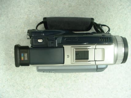
Click to zoom
Application Details
- Equipment Class
- DSS - Part 15 Spread Spectrum Transmitter
- Date of Grant
- Jan 24, 2003
- Application Purpose
- Original Equipment
- Date of Application
- Jan 24, 2003
- Equipment Note
- Digital Video Camera Recorder with Bluetooth
- Frequency Range
- 2402.00000000 - 2480.00000000
- Company
- Sony Group Corporation
- Country
- Japan
Documents & Files
Document Text
Text extracted from the exhibit documents filed with the FCC. Open a document above to read the original.
External Photos
EXTERNAL PHOTO SONY CORPORATION FCC ID: AK8DCRTRV80 Front View Rear View EXTERNAL PHOTO SONY CORPORATION FCC ID: AK8DCRTRV80 Right Hand Side Left Hand Side EXTERNAL PHOTO SONY CORPORATION FCC ID: AK8DCRTRV80 Top View Bottom View EXTERNAL PHOTO SONY CORPORATION FCC ID: AK8DCRTRV80 Over View without Lens Cover Over View with Lens Cover
ID Label/Location Info
DCR-TRV80 Label locationfor U.S.A Nameplate statement FCC ID Right Side Bottom
Internal Photos
INTERNAL PHOTO SONY CORPORATION FCC ID: AK8DCRTRV80 Cover Opened Cover Opened (No.2) INTERNAL PHOTO SONY CORPORATION FCC ID: AK8DCRTRV80 Antenna and Circuit Board (Connected) Antenna Connected INTERNAL PHOTO SONY CORPORATION FCC ID: AK8DCRTRV80 Circuit Connected Antenna and Circuit Board (Front) INTERNAL PHOTO SONY CORPORATION FCC ID: AK8DCRTRV80 Antenna and Circuit Board (Back) Circuit Board (Front) INTERNAL PHOTO SONY CORPORATION FCC ID: AK8DCRTRV80 Circuit Board (Back) Antenna (Front) INTERNAL PHOTO SONY CORPORATION FCC ID: AK8DCRTRV80 Antenna (Back)
Operational Description
Description of Frequency Hopping Spread Spectrum (in accordance with requirement of FCC 15.247 (a), (g) and (h)) 1. Bluetooth system The Equipment Under Test (EUT) is the Digital Video Camera Recorder, witch has a Bluetooth communication module internally. Bluetooth is the one of the short-range wireless communication system with frequency hopping spread spectrum (FHSS). Bluetooth Specification is standardized by and published by Bluetooth Special Interest Group (SIG). This EUT is completely applied to The Bluetooth Specification ver. 1.1 released in February 22nd, 2001. 2. Hopping Frequency The frequency range is 2402 MHz to 2480 MHz with spanning 79MHz. Hopping frequencies (channels) are separated by 1MHz within 20 dB bandwidth. Therefore there are 79 hopping frequencies. These hopping frequencies are selected by pseudo random sequence so that each frequency must be used equally on the average. The slot length of Bluetooth is separated by 625 microsecond and Bluetooth specifications allow a multi slots packet using these slots, up to five slots without an interval. A hopping frequency occupies over this multi slots packet and the longest occupancy is 3.125 millisecond, in case of a five-slot packet. 3. Hopping Sequence The hopping frequencies are selected derived from the Bluetooth clock and the Bluetooth BD_Address, which is a unique ID for unit by unit. In case of channel hopping sequence, 79 Hop frequencies distributed equally over the 79MHz. * Sequence example 1: 8, 66, 10, 70, 12, 19, 14, 23, 16, 1, 18, 5, 20, 33, 22, 37, 24, 3, 26, 7, 28, 35, 30, 39, 32, 72, 34, 76, 36, 25, 38, 29, 40, 74, 42, 78, 44, 27, 46, 31, 48, 9, 50, 13, 52, 41, 54, 45 * Sequence example 2: 55, 26, 19, 20, 23, 22, 53, 40, 57, 42, 21, 36, 25, 38, 27, 63, 31, 65, 74, 59, 78, 61, 29, 0, 33, 02, 76, 75, 01, 77, 35, 71, 39, 73, 3, 67, 7, 69, 37, 8, 41, 10, 5, 4, 9, 6, 43, 16 In case of inquiry/page mode, 32 hop frequencies distributed equally over the 79MHz. * Sequence example 1: 48, 50, 09, 13, 52, 54, 41, 45, 56, 58, 11, 15, 60, 62, 43, 47, 00, 02, 64, 68, 04, 06, 17, 21, 08, 10, 66, 70, 12, 14, 19, 23, 48, 50, 09, 13, 52, 54, 41, 45, 56, 58, 11, 15, 60, 62, 43, 47 * Sequence example 2: 41, 05, 10, 04, 09, 43, 06, 16, 47, 11, 18, 12, 15, 45, 14, 32, 49, 13, 34, 28, 17, 51, 30, 24, 55, 19, 26, 20, 23, 53, 22, 40, 41, 05, 10, 04, 09, 43, 06, 16, 47, 11, 18, 12, 15, 45, 14, 32 Where, 0 - 78 is 2402MHz - 2480MHz. In the Both modes, selected 32/79 hop frequencies are changed by pseudo random sequence one after another. And cycling time is so long, because the code length is 2^27-1. 4. Creating connection Short-range wireless communication network of Bluetooth, called piconet, is established as following. One “Master” unit searches for other “Slave” units in surrounding area, which is called “Inquiry”. If at least one “Slave” is found, “Master” can try to create connection with it, which is called “Page”. After the connection is established, “Master” unit controls the hopping sequence in the piconet. In this case, “Master” unit’s BD_Address is us used to generate hopping sequence.
Operational Description
Operation Description 1.Sending The sending base-band 1Mbps signal is divided two signals, I and Q. DAC and filter remove unnecessary high frequency from signals. Besides, the signal at 2.4GHz after passing the first local oscillator goes through phase converter. And it is transformed phase difference-90°signal, goes into multiplication unit of I and Q. At Addition unit, GFSK-modulation occurs by adding I and Q. The modulated carrier waves go through balanced-unbalanced unit after amplification at amp. And the signal is sent after the harmonic waves from local oscillator and power amp distortion are removed from the signal by band-pass-filter. 2.Receiving At first, the disturbance electric waves outside of used band are removed from the input carrier waves by band-pass-filter. After going through balanced-unbalanced unit, the receiving signal is amplified by low-noise-amp and go into mix unit. And the signal is transformed the middle frequency at 1.5MHz after it is multiplied 1.5MHz lower signal than the carrier waves of 2.4GHz-band that double the frequency from the local oscillator of 1.2GHz- band. The middle frequency signal is removed disturbance electric waves inside used band by passing inside of band-pass-filter. After the signal at 1.5MHz from the second local oscillator is multiplied at multiplication unit, Q and I are added at addition unit. And added signal, Q, and I are demodulated to base-band signal after removing unnecessary high frequency by low-pass-filter. 3.Antenna location There is an antenna inside the video camera recorder. It is impossible to remove the antenna and to change this.
Test Report
Test report No. : 23CE0075-HO-2 Page : 2 of 143 Issued date : November 29, 2002 FCC ID : AK8DCRTRV80 A-Pex International Co., Ltd. EMC Head Office Division. 4383-326 Asama-cho, Ise-shi, Mie-ken 516-0021 JAPAN CONTENTS PAGE SECTION 1: Client information 3 SECTION 2: Equipment under test (E.U.T.) 3 SECTION 3: Test specification, procedures and results 5 SECTION 4: Operation of E.U.T. during testing 7 SECTION 5: Conducted Emission, Section 15.207 10 SECTION 6: Carrier Frequency Separation , Section15.247(a)(1) 10 SECTION 7: 20dB Bandwidth, Section 15.247(a)(1) 10 SECTION 8: Number of Hopping Frequency, Section 15.247(a)(1)(iii) 11 SECTION 9: Dwell time, Section 15.247(a)(1)(iii) 11 SECTION 10: Maximum Peak Output Power, Section 15.247(b)(1) 11 SECTION 11: Band Edge compliance, Section 15.247(c) 11 SECTION 12: Spurious Emission, Section 15.247(c) 12 APPENDIX 1: Photographs of test setup 13 APPENDIX 2: Data of EMI test 13 APPENDIX 3: Test instruments 13 Telephone : +81 596 24 8116 Facsimile : +81 596 24 8124 Test report No. : 23CE0075-HO-2 Page : 3 of 143 Issued date : November 29, 2002 FCC ID : AK8DCRTRV80 A-Pex International Co., Ltd. EMC Head Office Division. 4383-326 Asama-cho, Ise-shi, Mie-ken 516-0021 JAPAN SECTION 1: Client information Company name : Sony Corporation Address : 6-7-35 Kitashinagawa, Shinagawa-ku, Tokyo 141- 0001 Japan Telephone Number : +81-3-5769-5643 Facsimile Number : +81-3-5769-5963 Contact Person : Susumu Ishiwata SECTION 2: Equipment under test (E.U.T.) 2.1 Identification of E.U.T. Type of Equipment : Digital Video Camera Recorder Model No. : DCR-TRV80 Serial No. : 111, 175 module Ver.A 108, 172 module Ver.B Rating : DC 7.2V AC Adaptor AC 120V/60Hz Country of Manufacture : Japan Receipt Date of Sample : November 14, 2002 Condition of EUT : Engineering prototype Telephone : +81 596 24 8116 Facsimile : +81 596 24 8124 Test report No. : 23CE0075-HO-2 Page : 4 of 143 Issued date : November 29, 2002 FCC ID : AK8DCRTRV80 A-Pex International Co., Ltd. EMC Head Office Division. 4383-326 Asama-cho, Ise-shi, Mie-ken 516-0021 JAPAN 2.2 Product Description Model: DCR-TRV80 which was referred to as the EUT in this report is a Digital Video Camera Recorder. The specification is as following; Equipment Type : Transceiver Clock frequency used in EUT : 67.5MHz Frequency characteristics : from 2400MHz to 2483.5MHz Number of Channel/ Channel spacing : 79 channels/ 1MHz Modulation : FSK (Frequency Shift Keying) and FHSS (Frequency Hopping Spread Spectrum) Antenna Type : External grounded planner inverted-F type antenna Antenna Gain : 0 dBi ITU code : F1D *FCC Part 15.31 (e) The host device DCR-TRV80 provide the stable power supply (DC: 7.2V), and the Digital Video Camera Recorder complies power supply regulation. *FCC Part 15.203 Antenna requirement Digital Video Camera Recorder and its antenna comply with this requirement since they are built in host device DCR-TRV80 when they are put up for sale and they are used with a particular antenna connector. Telephone : +81 596 24 8116 Facsimile : +81 596 24 8124 Test report No.: 23CE0075-HO-2 Page: 5 of 143 Issued date: November 29, 2002 FCC ID: AK8DCRTRV80 A-Pex International Co., Ltd. EMC Head Office Division . 4383-326 Asama-cho, Ise-shi, Mie-ken 516-0021 JAPAN Telephone: +81 596 24 8116 Facsimile: +81 596 24 8124 SECTION 3: Test specification, procedures and results 3. 1Test Specification Test Specification: FCC Part 15 Subpart C Title: FCC 47CFR Part15 Radio Frequency Device Subpart C Intentional Radiators Section 15.207 Conducted Emissions Section 15.247 Operation within the Band 902-928MHz, 2400-2483.5MHz, and 5725-5850MHz 3.2Procedures and results No.ItemTest ProcedureSpecificationRemarksDeviationWorst marginResults 1 Conducted Emission ANSI C63.4:2001Section 15.207N/AN/A18.48dB 4.8831MHz, N Complied 2Carrier Frequency Separation ANSI C63.4:2001Section15.247(a)(1)ConductedN/AN/AComplied 320dB BandwidthANSI C63.4:2001Section15.247(a)(1)ConductedN/AN/AComplied 4 Number of Hopping Frequency ANSI C63.4:2001Section15.247(a)(1)(iii)ConductedN/AN/AComplied 5Dwell timeANSI C63.4:2001Section15.247(a)(1)(iii)ConductedN/AN/AComplied 6 Maximum Peak Output Power ANSI C63.4:2001Section15.247(b)(1)ConductedN/AN/AComplied 7 Band Edge Compliance ANSI C63.4:2001Section15.247(c)ConductedN/AN/AComplied 8 Spurious Emission ANSI C63.4:2001Section15.247(c)Conducted / Radiated N/A3.1dB 270.00MHz Horizontal Complied These tests were also referred to FCC Public Notice DA 00-705 "Guidance on Measurement for Frequency Hopping Spread Spectrum Systems. 3.3Additions to Standards No addition, deviation or exclusion has been made from standards. 3.4Confirmation A-Pex International hereby confirms that E.U.T., in the configuration tested, complies with the specifications FCC Part 15 Subpart C Section 15.207 and 15.247. Test report No.: 23CE0075-HO-2 Page : 6 of 143 Issued date : November 29, 2002 FCC ID : AK8DCRTRV80 A-Pex International Co., Ltd. EMC Head Office Division. 4383-326 Asama-cho, Ise-shi, Mie-ken 516-0021 JAPAN Telephone : +81 596 24 8116 Facsimile : +81 596 24 8124 3.5 Uncertainty Conducted Emission The measurement uncertainty (with a 95% confidence level) for this test was ±1.3dB. The data listed in this test report has enough margin, more than the site margin. Spurious Emission(Radiated) The measurement uncertainty (with a 95% confidence level) for this test using Biconical antenna is ±4.5dB. The measurement uncertainty (with a 95% confidence level) for this test using Logperiodic antenna is ±5.2dB. The measurement uncertainty (with a 95% confidence level) for this test using Horn antenna is ±6.6dB. The data listed in this test report may exceed the test limit because it does not have enough margin. Other test except Conducted Emission and Spurious Emission(Radiated) The measurement uncertainty (with a 95% confidence level) for this test was ±3.0dB. . The data listed in this test report has enough margin. 3.6 Test Location A-Pex International Co., Lt…
Text truncated - open the document above for the full version.
Test Setup Photos
Test report No. : 23CE0075-HO-2 Page : 14 of 143 Issued date : November 29, 2002 FCC ID : AK8DCRTRV80 A-Pex International Co., Ltd. EMC Head Office Division. 4383-326 Asama-cho, Ise-shi, Mie-ken 516-0021 JAPAN APPENDIX 1: Photographs of test setup Conducted Emission Telephone : +81 596 24 8116 Facsimile : +81 596 24 8124 Test report No. : 23CE0075-HO-2 Page : 15 of 143 Issued date : November 29, 2002 FCC ID : AK8DCRTRV80 A-Pex International Co., Ltd. EMC Head Office Division. 4383-326 Asama-cho, Ise-shi, Mie-ken 516-0021 JAPAN Spurious Emission(Radiated) Telephone : +81 596 24 8116 Facsimile : +81 596 24 8124 Test report No. : 23CE0075-HO-2 Page : 16 of 143 Issued date : November 29, 2002 FCC ID : AK8DCRTRV80 A-Pex International Co., Ltd. EMC Head Office Division. 4383-326 Asama-cho, Ise-shi, Mie-ken 516-0021 JAPAN Other test except Conducted Emission and Spurious Emission(Radiated) Telephone : +81 596 24 8116 Facsimile : +81 596 24 8124
Contact Information
Applicant
Kazuyuki Hori(Chief EMC/RF Compliance Specialist)
Technical Contact
A-Pex International Co., Ltd.Hiroka Umeyama
[email protected]81-596-24-8116
4383-326 Asama-cho, · Ise-shi, Mie-ken · Japan
Non-Technical Contact
A-Pex International Co., Ltd.Kanako Sanda
[email protected]81-596-24-8116
Test Firm
UL Apex Co., Ltd.Tetsuya Hashimoto
Technical Specifications
| # | Rule Parts | Frequency Range | Power Output |
|---|---|---|---|
| 1 | 15C | 2.40 GHz - 2.48 GHz | 1.02 mW |
Other Applications from Sony Group Corporation
AK8WW81782
Aug 21, 2026Radio Equipment
Equipment Class
DSS - Part 15 Spread Spectrum TransmitterAK8CFIZCP2
Aug 03, 2026Wireless Controller
Equipment Class
DSS - Part 15 Spread Spectrum TransmitterAK8OEV321MUH
Apr 14, 2026LCD Monitor
Equipment Class
JAD - Part 15 Class A Digital DeviceAK8OEV431MUH
Apr 14, 2026LCD Monitor
Equipment Class
JAD - Part 15 Class A Digital DeviceAK8OEV271MUH
Apr 14, 2026LCD Monitor
Equipment Class
JAD - Part 15 Class A Digital Device