AK8DEHR1000Reference Tool
Sony Group Corporation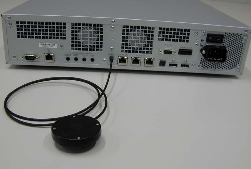
Click to zoom
Application Details
- Equipment Class
- DTS - Digital Transmission System
- Date of Grant
- Jul 25, 2006
- Application Purpose
- Original Equipment
- Date of Application
- Jul 24, 2006
- Equipment Note
- Reference Tool
- Frequency Range
- 2412.00000000 - 2462.00000000
- Company
- Sony Group Corporation
- Country
- Japan
Documents & Files
Document Text
Text extracted from the exhibit documents filed with the FCC. Open a document above to read the original.
Users Manual
DECR-1000 A 2-886-333-11(1) G:\Sagyou\07 Jul\0706\837913S DECR-1000 A_GB\2886333111DEHR1000\01GB01COV.fm masterpage:Right Reference Tool Instruction manual SCE CONFIDENTIAL This manual contains safety precautions for the prevention of accidents, and instructions for the use and handling of this product. Read this manual carefully and use the product in a safe manner. After reading the manual, store it in an accessible location for future reference. DECR-1000 A 2-886-333-11(2) 01GB01COV.book Page 1 Thursday, July 6, 2006 2:50 PM DECR-1000 A 2-886-333-11(1) 2 Important safeguards G:\Sagyou\07 Jul\0706\837913S DECR-1000 A_GB\2886333111DEHR1000\01GB02REG.fm masterpage:HL1_L Important safeguards For your protection, please read these safety instructions completely before operating the appliance, and keep this manual for future reference. Carefully observe all warnings, precautions and instructions on the appliance, or those described in the instruction manual and adhere to them. Power sources This unit should be operated only from the type of power source indicated on the marking label. If you are not sure of the type of electrical power supplied to your home, consult your dealer or local power company. For those units designed to operate from battery power, or other sources, refer to the operating instructions. Overloading Do not overload wall outlets, extension cords or convenience receptacles beyond their capacity, since this can result in fire or electric shock. Liquid and foreign objects Never push objects of any kind into the unit through openings as they may touch dangerous voltage points or short out parts that could result in a fire or electric shock. Never spill liquid of any kind on the unit. Attachments Do not use attachments not recommended by the manufacturer, as they may cause hazards. Cleaning Unplug the unit from the wall outlet before cleaning or polishing it. Do not use liquid cleaners or aerosol cleaners. Use a cloth lightly dampened with water for cleaning the unit exterior. Water and moisture Do not use the powerline operated unit near water – for example, near a bathtub, washbowl, kitchen sink, or laundry tub, in a wet basement or near a swimming pool, etc. Power cord protection Route the power cord so that it is not likely to be walked on or pinched by items placed upon or against it, paying particular attention to the plugs, receptacles, and the point where the cord exits from the unit. Ventilation The slots and openings in the cabinet are provided for necessary ventilation. To ensure reliable operation of the unit, and to protect it from overheating, these slots and openings must never be blocked or covered. – Never cover the slots and openings with a cloth or other materials. – Never block the slots and openings by placing the unit on a bed, sofa, rug or other similar surface. Accessories Do not place the unit on an unstable cart, stand, bracket or table. The unit may fall, causing serious injury to a child or an adult, and serious damage to the unit. Use only a cart, stand, tripod, bracket, or table recommended by the manufacturer. An appliance and cart combination should be moved with care. Quick stops, excessive force, and uneven surfaces may cause the appliance and cart combination to overturn. – Never place the unit in a confined space, such as a bookcase, or built-in cabinet, unless proper ventilation is provided. – Do not place the unit near or over a radiator or heat register, or where it is exposed to direct sunlight. USE INSTALLATION 01GB01COV.book Page 2 Thursday, July 6, 2006 2:50 PM DECR-1000 A 2-886-333-11(1) G:\Sagyou\07 Jul\0706\837913S DECR-1000 A_GB\2886333111DEHR1000\01GB02REG.fm masterpage:Right 3 Important safeguards Important safeguards Damage requiring service Unplug the unit from the wall outlet and refer servicing to qualified service personnel under the following conditions: – When the power cord or plug is damaged or frayed. – If liquid has been spilled or objects have fallen onto the unit. – If the unit has been exposed to rain or water. – If the unit has been subject to strong physical shock by being dropped, or the cabinet has been damaged. – If the unit does not operate normally when following the instruction manual. Adjust only those controls that are specified in the instruction manual. Improper adjustment of other controls may result in damage and will often require extensive work by a qualified technician to restore the unit to normal operation. – When the unit exhibits a distinct change in performance – this indicates a need for service. Servicing Do not attempt to service the unit yourself as opening or removing the exterior casing may expose you to dangerous voltage or other hazards. Refer all servicing to an authorized service center. Refer to the contact information on the back cover to receive instructions on obtaining repair/replacement services. Replacement parts When replacement parts are required, be sure the service technician has used replacement parts specified by the manufacturer that have the same characteristics as the original parts. Unauthorized substitutions may result in fire, electric shock, or other hazards. Safety check Upon completion of any service or repairs to the unit, ask the service technician to perform routine safety checks (as specified by the manufacturer) to determine that the unit is in safe operating condition. SERVICE 01GB01COV.book Page 3 Thursday, July 6, 2006 2:50 PM DECR-1000 A 2-886-333-11(1) G:\Sagyou\07 Jul\0706\837913S DECR-1000 A_GB\2886333111DEHR1000\01GB01COVTOC.fm masterpage:Left 4Table of contents Table of contents Important safeguards ......................................................................................................... 2 Precautions ........................................................................................................................ 5 1 Overview Overview of the reference system .................................................................…
Text truncated - open the document above for the full version.
Cover Letter(s)
William Graff From: [email protected] Sent: Wednesday, July 26, 2006 9:38 AM To: William Graff Cc: [email protected]; [email protected]; [email protected]; [email protected] Subject: Re: www.AmericanTCB.com ATCB003795 | AK8DEHR1000 | 409B - DEHR1000 | | AK8DEHR1000_ATCB003795 7/26/2006 Dear Bill, Hello, thank you for your comments. Please see our below purple message. Best regards, -------------------------------------------- Akane YAMAMOTO(Ms.) UL Apex Co., Ltd. EMC Service Division Application Group 4383-326 Asama-cho Ise-shi Mie-ken 516-0021 Japan TEL: +81-(0)596-24-8116 FAX: +81-(0)596-24-8095 E-Mail: [email protected] URL: http://www.ulapex.jp --------------------------------------------- Regarding www.AmericanTCB.com application: ATCB ID: ATCB003795 FCC ID: AK8DEHR1000 IC ID: 409B - DEHR1000 NB ID: Account name: akane Hello, Akane, So far there are only three issues I see with this filing. 1.) Are the WLAN and Bluetooth devices able to transmit simultaneously? If so, then the RF Exposure information must account for the sum of both transmitters operating simultaneously. Unless I have read this filing wrong, we need to make an adjustment to the RF Exposure exhibit to take into this effect. As we stated Page 3 of test report (26KE0202-HO-A & 26KE0202-HO-B), this product cannnot be operated simultaneously. 2.) What would you like to call this device? Would you like the Grant to say "William Graff" <[email protected]> 2006/07/25 20:47 To <[email protected]> cc <[email protected]>, <[email protected]>, <[email protected]> Subject www.AmericanTCB.com ATCB003795 | AK8DEHR1000 | 409B - DEHR1000 | | AK8DEHR1000_ATCB003795 "Multimedia Development Reference Tool"? Please state as "Reference Tool". 3.) Is the end user able to change channels or have control over different region channel sets? For US and Canada you should only allow for 802.11b/g Channels 1-11 to be implemented. The end user cannot be given the opportunity to operate on any non-US channel sets. Page 35 of Manual may be interpreted as allowing for "region selection". This product is to be shipped Europe as well, and the same user manual is to be used so that the specification in Europe is contained. However, regarding to channel establishment, the maker is set up before the shipment so that the enduser cannot choose the channel by themself. This product for US and Canada can be used only channel 1 to 11. Best Regards, Bill - For more information about UL, its Marks, and its services for EMC, quality registrations and product certifications for global markets, please access our web sites at http://www.ul.com and http://www.ul-asia.com or contact your local sales representative. -- ********* Internet E-mail Confidentiality Disclaimer ********** This e-mail message may contain privileged or confidential information. If you are not the intended recipient, you may not disclose, use, disseminate, distribute, copy or rely upon this message or attachment in any way. If you received this e-mail message in error, please return by forwarding the message and its attachments to the sender. UL and its affiliates do not accept liability for any errors, omissions, corruption or virus in the contents of this message or any attachments. ***************************************************************** 7/26/2006
External Photos
Sony Corporation Reference Tool Model: DECR-1000A FCC ID: AK8DEHR1000 IC Number: 409B-DEHR1000 External Photo(Antenna) Antenna with Machine body Antenna Sony Corporation Reference Tool Model: DECR-1000A FCC ID: AK8DEHR1000 IC Number: 409B-DEHR1000 Front View Rear View
External Photos
Sony Corporation Reference Tool Model: DECR-1000A FCC ID: AK8DEHR1000 IC Number: 409B-DEHR1000 External Photo Front View Rear View Sony Corporation Reference Tool Model: DECR-1000A FCC ID: AK8DEHR1000 IC Number: 409B-DEHR1000 Right Side View Left Side View Sony Corporation Reference Tool Model: DECR-1000A FCC ID: AK8DEHR1000 IC Number: 409B-DEHR1000 Top View Bottom View
ID Label/Location Info
Label DesignLabel Location
Internal Photos
Sony Corporation Reference Tool Model: DECR-1000A FCC ID: AK8DEHR1000 IC Number: 409B-DEHR1000 Internal Photo Front View Front View of Module Sony Corporation Reference Tool Model: DECR-1000A FCC ID: AK8DEHR1000 IC Number: 409B-DEHR1000 Front View of RF Connecter with Shielding Top View of RF Connecter with Shielding Sony Corporation Reference Tool Model: DECR-1000A FCC ID: AK8DEHR1000 IC Number: 409B-DEHR1000 Front View of RF Connecter without Shielding Top View of RF Connecter without Shielding Sony Corporation Reference Tool Model: DECR-1000A FCC ID: AK8DEHR1000 IC Number: 409B-DEHR1000 Top View of RF Connecter without module cover Rear View of RF Connecter without module cover
Operational Description
WLAN-BT-explanation.txt ======= WLAN ========= (1) Transmit Path (a) 88W8580 (U1) The transmitting data comes from the computer block via the 100BASE-FX conforming interface port accordig to the 100BASE-FX interface protocol. The Fast Ehternet MAC and 802.3 PHY in 88W8580(U1) perform the 100BASE-FX conforming communication control. The incomming transmitting data is transfered to the 802.11 Dual MAC via the Internal Bus. The 802.11 Dual MAC does the protocol control, media access control, and the generation of transmit data frame. The 802.11 Dual MAC has the carrier sense function also, then it does the carrier detection base on RSSI. The 802.11 baseband modulates the generated transmit data frame by 64QAM, 16QAM, QPSK, BPSK, CCK, DQSK, or DBPSK according to the transfer data rate, and the 802.11 baseband generates I,Q baseband signals. The DACs convert the modulated digital I,Q baseband signal to the analog baseband signals, and these analog baseband signals are delivered from 88W8580(U1) to 88W8010(U2). (b) 88W8010 (U2) The inputted baseband signals are converted to 482.4MHz-494.44MHz IF signal (1MHz step, 1-13 channels) according to the channel frequency by the Local Oscillator(LO) and the IF mixer. Next, the RF Mixer converts the IF signal to the 2412MHz-2472MHz RF signal (5MHz step 1-13channels). Gain adjustment of the RF signal is carried out by the bias controlled Variable Gain Amp (VGA), it is amplified by Power Amp (PA), and 88W8010(U2) outputs the amplified RF signal. (c) Balun(BA1), Tx/Rx SW(U6), BPF(BP1) The Balun(BA1) converts the balanced RF signal which is provided from 88W8010(U2) to unbalanced RF signal. And it pass through the Tx/Rx SW(U6) and the Band Pass Filter BPF(BP1). The band-width of the RF signal is limitted by the BPF(BP1). The RF signal is delivered to ANT SW(U7). The 88W8580(U1) does the timing control of the Tx/Rx SW(U6) using a control signal. (d) ANT SW(U7) The RF signal from BPF(BP1) is delivered to selected BGA PAD (ANT0 or ANT1) according to the 888W8580's control signal. The ANT1 BGA PAD is connected to the Original RF Connector via the Divider. And the external monopole antenna is connected to the Original RF Connector. Then the transmit RF signal is radiated from the monopole antenna. (2) Receive Path (a) ANT SW(U6) The receiving RF signal comes from the external monopole antenna. It passes through the RF original connector and the ANT1 BGA Pad under the Wireless LAN module via the Divider and it goes into the module. The RF signal is delivered to BPF(BP1) via ANT SW(U6). (b) BPF(BP1), Tx/Rx SW(U6), 88W8010(U2) The receiving RF signal pass through the BPF(BP1) and its (1) WLAN-BT-explanation.txt out-of-band spurious is eliminated by the BPF. The RF signal is pass through the 88W8010(U2) via Tx/Rx SW(U6). The 88W8010(U2) amplifies the RF signal to an apropriate level RF signal by the 88W8010's Low Noise Amp(LNA). The RF mixer generates 482.4MHz-494.4MHz IF signal (1MHz step, 1-13 channels) from the RF signal and the the 1929.6-1977.6MHz signal which is delivered from Local Oscillator(LO). The other RF mixers and filters convert from the IF signal to analog I,Q baseband signals. The analog I, Q baseband signals are amplified to an appropriate level and they are delivered to 88W8580(U1). (c) 88W8580(U1) The 802.11 Baseband converts the analog I, Q signals to digital baseband signals by ADCs. The digital baseband signals are demodulated to receiving data frame by 64QAM, 16QAM, QPSK, BPSK, CCK, DQSK, or DBPSK according to the transfer data rate. The receiving data frame is provided to the 802.11 MAC and the 802.11 MAC takes the receiving data from the receiving data frame. By the receiving data is transfered to 100BASE-FX Conforming Interface via Internal Bus, 802.3PHY and Fast Ethernet MAC, the 88W8580(U1) outputs the receiving data. The computer block receives the receiving data accrding to the 100BASE-FX interface protocol. ======= Bluetooth ========= (1) Reference clock oscillator and RF frequency synthesizer block The "Fref" reference clock is generated by IC001's oscillator circuit with X001 24MHz crystal resonator. The oscillator circuit is temperature-compensated and the tolerance of the oscillator is +/-20ppm in the temperature environment of -40 to +85 degrees C. The "Fref" reference clock is supplied to RF synthesizer block, micro controller block and Baseband and Logic block. The RF frequency synthesizer block has a Local Oscillator (VCO) and a RF synthesizer. The frequency of the Local Oscillator in IC001 is 2400.5MHz to 2478.5MHz at receiving time, and 2403MHz to 2481MHz at transmitting time. (2) RF Transmitter block The digital baseband data is provided from the Baseband and Logic Block. 1MHz frequency offset is added to the digital baseband data. And it is converted to baseband signal by DAC. The baseband signal is up-converted to 2.4GHz by the IQ modulator (IQ MOD). And RF amp amplifies its signal level and outputs balanced signal. The PLL synthesizer gives local oscillator output to the IQ modulator. The synthesizer generates around 1.6GHz signal. And the synthesizer mixes 1.6GHz signal and its half frequency signal (800MHz). Then it outputs 2.4GHz signal. The 2.4GHz signal passes through the 90 digrees phase splitter, and it gives the IQ drive signal to the modulator. The Differential signal output from the RF Amp is converted to unbalanced signal by L001,L002,L003,C009,C018. And the unbalanced signal pass through the IC003 RF switch (Tx/Rx switch) and FL001 Tx/Rx Band Pass Filter(BPF). It passes through the IC004 RF switch (ANT switch) and deriverd to the selected output RF Pad under the Bluetooth module. The output RF pad is connected to the Original RF original (2) WLAN-BT-explanation.txt connector, and the external monopole antenna is connected to the Original RF connector. Then the transmit signal is radiated from the monopole antenna. (3) RF Receiving block The receiving signal (2402 to 2480MHz) comes from the external mono…
Text truncated - open the document above for the full version.
RF Exposure Info
UL Apex Co., Ltd. Head Office EMC Lab. 4383-326 Asama-cho, Ise-shi, Mie-ken 516-0021 JAPAN Telephone : +81 596 24 8116 Facsimile : +81 596 24 8124 Applicant: Sony Computer Entertainment Inc. Type of Equipment : REFERENCE TOOL (WLAN module part) Model No. : DECR-1000A FCC ID: AK8DEHR1000 Sony Computer Entertainment Inc. declares that Model : DECR-1000 A complies with FCC radiation exposure requirement specified in the FCC Rules 2.1093(for portable)/2.1091 (for mobile). RF Exposure Calculations: The following information provides the minimum separation distance for the highest gain antenna provided with the “DECR-1000A“ as calculate d from FCC OET Bulletin 65 Appendix A, Table (B) Limits for General Population / Uncontrolled Exposure. This calculation is based on the highest EIRP possible from the system, considering maximum power and antenna gain, and considering a 1.0mW/cm^2 uncontrolled exposure limit. The Friis formula used was: S = (P * G) / (4* π * r 2 ) Where P = 36.31 mW (Maximum peak output power) G = 1.62 Numerical Antenna gain; equal t2.09 dBi r =20.0 cm For: DECR-1000AS = 0.01169 mW/cm 2 No. : 26KE0202-HO-B RF Exposure Statement
Test Report
Test report No. : 26KE0202-HO-B Page : 2 of 62 Issued date : July 24, 2006 FCC ID : AK8DEHR1000 UL Apex Co., Ltd. Head Office EMC Lab. 4383-326 Asama-cho, Ise-shi, Mie-ken 516-0021 JAPAN Telephone : +81 596 24 8116 Facsimile : +81 596 24 8124 MF060b(14.06.06) CONTENTS PAGE SECTION 1: Client information ............................................................................................................ 3 SECTION 2: Equipment under test (E.U.T.)........................................................................................ 3 SECTION 3: Test specification, procedures & results......................................................................... 5 SECTION 4: Operation of E.U.T. during testing .................................................................................9 SECTION 5: Conducted Emission....................................................................................................... 13 SECTION 6: Spurious Emission.......................................................................................................... 14 SECTION 7: Bandwidth ....................................................................................................................... 15 SECTION 8: Maximum Peak Output Power ..................................................................................... 15 SECTION 9: Peak Power Density........................................................................................................ 15 APPENDIX 1: Photographs of test setup ............................................................................................ 16 Conducted Emission .......................................................................................................................................16 Spurious Emission (Radiated) .......................................................................................................................17 Antenna Worst Case Position (Horizontal: X-axis/ Vertical:Y-axis) .........................................................18 APPENDIX 2:Test instruments ............................................................................................................ 19 APPENDIX 3: Data of EMI test............................................................................................................ 21 Conducted Emission .......................................................................................................................................21 6dB Bandwidth ...............................................................................................................................................29 Maximum Peak Output Power......................................................................................................................32 Radiated Spurious Emission (30MHz-1GHz) ..............................................................................................33 Radiated Spurious Emission (1GHz-26GHz) ...............................................................................................41 Conducted Spurious Emission.......................................................................................................................49 Conducted emission Band Edge compliance ................................................................................................57 Power Density .................................................................................................................................................58 99%Occupied Bandwidth ..............................................................................................................................61 Test report No. : 26KE0202-HO-B Page : 3 of 62 Issued date : July 24, 2006 FCC ID : AK8DEHR1000 UL Apex Co., Ltd. Head Office EMC Lab. 4383-326 Asama-cho, Ise-shi, Mie-ken 516-0021 JAPAN Telephone : +81 596 24 8116 Facsimile : +81 596 24 8124 MF060b(14.06.06) SECTION 1: Client information Company Name Sony Computer Entertainment Inc. Brand Name SONY Address 2-6-21 Minamiaoyama, Minato-ku, Tokyo, 107-0062, Japan Telephone Number +81-3-6438-8625 Facsimile Number +81-3-6438-8607 Contact Person Akiko Tsukada SECTION 2: Equipment under test (E.U.T.) 2.1 Identification of E.U.T. Type of Equipment REFERENCE TOOL Model No DECR-1000A Serial No SR000001 Rating AC 120V/60Hz Country of Manufacture JAPAN Receipt Date of Sample June 20, 2006 Condition of EUT Production prototype (Not for Sale: This sample is equivalent to mass-produced items.) Modification of EUT No modification by the test lab. 2.2 Product Description Model: DECR-1000A, referred to as the EUT in this report, is a REFERENCE TOOL to make software for game. It contains Bluetooth (Ver. 2.0+EDR) module and IEEE802.11b/g WLAN module. Those modules do not transmit simultaneously. Bluetooth (Ver. 2.0+EDR) Equipment Type Transceiver Frequency of Operation 2402-2480MHz Type of Modulation FHSS (GFSK, π/4DQPSK, 8DPSK) Bandwidth & Channel spacing 1MHz & 1MHz Power Supply (inner) DC3.3V *For Bluetooth module test, please see UL Apex Test Report No. 26KE0202-HO-A. IEEE802.11b/g WLAN Equipment Type Transceiver Frequency of Operation 2412-2462MHz Type of Modulation DSSS/OFDM Bandwidth & Channel spacing 20MHz & 5MHz Power Supply (inner) DC 3.3V/DC1.3V Test report No. : 26KE0202-HO-B Page : 4 of 62 Issued date : July 24, 2006 FCC ID : AK8DEHR1000 UL Apex Co., Ltd. Head Office EMC Lab. 4383-326 Asama-cho, Ise-shi, Mie-ken 516-0021 JAPAN Telephone : +81 596 24 8116 Facsimile : +81 596 24 8124 MF060b(14.06.06) [Antenna] Antenna Type Monopole Antenna (Common antenna for Bluetooth and WLAN module) Antenna Connector Type SMK TS-6 connector with custom key Antenna Gain 2.09dBi max Test report No. : 26KE0202-HO-B Page : 5 of 62 Issued date : July 24, 2006 FCC ID : AK8DEHR1000 UL Apex Co., Ltd. Head Office EMC Lab. 4383-326 Asama-cho, Ise-shi, Mie-ken 516-0021 JAPAN Telephone : +81 596 24 8116 Facsimile : +81 596 24 8124 MF060b(14.06.06) SECTION 3: Test specifica…
Text truncated - open the document above for the full version.
Test Report
Test report No. : 26KE0202-HO-B Page : 19 of 62 Issued date : July 24, 2006 FCC ID : AK8DEHR1000 UL Apex Co., Ltd. Head Office EMC Lab. 4383-326 Asama-cho, Ise-shi, Mie-ken 516-0021 JAPAN Telephone : +81 596 24 8116 Facsimile : +81 596 24 8124 MF060b(14.06.06) APPENDIX 2:Test instruments Control No. Instrument Manufacturer Model No Test Item Calibration Date * Interval(month) MAEC-04 Anechoic Chamber TDK Semi Anechoic Chamber 3m RE 2006/03/06 * 12 MCC-50 Coaxial cable UL Apex - RE / CE 2006/03/09 * 12 MAT-31 Attenuator(6dB) TME UFA-01 RE 2006/03/11 * 12 MPA-14 Pre Amplifier SONOA INSTRUMENT 310 RE 2006/03/25 * 12 MBA-05 Biconical Antenna Schwarzbeck BBA9106 RE 2006/01/29 * 12 MLA-08 Logperiodic Antenna Schwarzbeck UKLP9140-A RE 2006/01/29 * 12 MOS-14 Thermo-Hygrometer Custom CTH-180 RE / CE 2006/01/19 * 24 MSA-05 Spectrum Analyzer Advantest R3273 RE 2006/05/20 * 12 MTR-02 Test Receiver Rohde & Schwarz ESCS30 RE 2006/02/02 * 12 MCC-57 Microwave Cable Suhner SUCOFLEX104 RE 2006/04/15 * 12 MPA-12 MicroWave System Amplifier Agilent 83017A RE 2006/03/27 * 12 MHA-05 Horn Antenna Schwarzbeck BBHA9120D RE 2006/01/09 * 12 MHA-02 Horn Antenna EMCO 3160-09 RE 2006/01/09 * 12 MCC-25 Microwave Cable 1G-26.5GHz Suhner SUCOFLEX104 RE 2005/08/30 * 12 MCC-26 Microwave Cable 1G-26.5GHz Suhner SUCOFLEX104 RE 2005/08/30 * 12 MPA-10 Pre Amplifier Agilent 8449B RE 2005/09/07 * 12 MAEC-02 Anechoic Chamber TDK Semi Anechoic Chamber 3m RE 2006/04/10 * 12 MBA-02 Biconical Antenna Schwarzbeck BBA9106 RE 2005/10/10 * 12 MLA-02 Logperiodic Antenna Schwarzbeck USLP9143 RE 2005/10/14 * 12 MCC-12 Coaxial Cable Fujikura/Agilent - RE 2006/02/23 * 12 MAT-07 Attenuator(6dB) Weinschel Corp 2 RE 2005/12/16 * 12 MPA-09 Pre Amplifier Agilent 8447D RE 2005/09/07 * 12 MRENT-31 Spectrum Analyzer Advantest R3273 RE 2006/04/24 * 12 MTR-03 Test Receiver Rohde & Schwarz ESCI RE 2006/03/04 * 12 MSTW-14 EMI measurement program TSJ TEPTO-DV RE - MOS-02 Digital Humidity Indicator N.T NT-1800 RE 2004/11/25 * 24 MOS-15 Thermo-Hygrometer Custom CTH-180 AT 2006/01/19 * 24 MOS-16 Thermo-Hygrometer Custom CTH-180 AT 2006/01/19 * 24 MSA-06 Spectrum Analyzer Agilent E4407B AT 2006/05/24 * 12 Test report No. : 26KE0202-HO-B Page : 20 of 62 Issued date : July 24, 2006 FCC ID : AK8DEHR1000 UL Apex Co., Ltd. Head Office EMC Lab. 4383-326 Asama-cho, Ise-shi, Mie-ken 516-0021 JAPAN Telephone : +81 596 24 8116 Facsimile : +81 596 24 8124 MF060b(14.06.06) Control No. Instrument Manufacturer Model No Test Item Calibration Date * Interval(month) MCC-06 Microwave Cable 1G-26.5GHz Suhner SUCOFLEX 104 AT 2006/02/02 * 12 MAT-22 Attenuator(10dB)(ab ove1GHz) Orient Microwave BX10-0476-00 AT 2006/03/18 * 12 MRENT-36 Power Meter Anritsu ML2496A AT 2006/04/25 * 12 MRENT-33 Power sensor Anritsu MA2411B AT 2006/04/25 * 12 MLS-06 LISN(AMN) Schwarzbeck NSLK8127 CE (AE) 2006/02/06 * 12 MLS-07 LISN(AMN) Schwarzbeck NSLK8127 CE (EUT) 2006/02/06 * 12 MTA-07 Terminator MCL BTRM-50 CE 2006/02/06 * 12 All equipment is calibrated with traceable calibrations. Each calibration is traceable to the national or international standards. Test Item: CE: Conducted Emission RE: Radiated Emission AT: Antenna Terminal Conducted Measurement Test report No. : 26KE0202-HO-B Page : 21 of 62 Issued date : July 24, 2006 FCC ID : AK8DEHR1000 UL Apex Co., Ltd. Head Office EMC Lab. 4383-326 Asama-cho, Ise-shi, Mie-ken 516-0021 JAPAN Telephone : +81 596 24 8116 Facsimile : +81 596 24 8124 MF060b(14.06.06) APPENDIX 3: Data of EMI test Conducted Emission DATA OF CONDUCTED EMISSION TEST UL Apex Co., Ltd. Head Office EMC Lab. No.4 Shielded room Date : 2006/07/19 16:27:59 Company : Sony Computer Entertainment Inc.Report No.:26KE0202-HO Kind of EUT : REFERENCE TOOL Power:AC120V / 60Hz Model No. : DECR-1000A Temp./Humi.:23deg.C / 74% Serial No. : SR000001 Operator:Takumi Shimada Mode / Remarks: WLAN 11b Tx 2412MHz 11Mbps LIMIT : FCC15C §15.207 (QP)/ RSS-Gen 7.2.2 FCC15C §15.207 (AV)/ RSS-Gen 7.2.2 CHART:WITH FACTOR,Peak hold data.Data is uncorrected. CALCURATION:RESULT=READING+C.F(LISN LOSS+CABLE LOSS) Except for the above table : adequate margin data below the limits. Frequency[Hz] [dBuV] << PEAK DATA >> N :PEAK .15M 30M .2M .3M .5M .7M 1M2M3M5M7M10M20M 0 10 20 30 40 50 60 70 80 90 100 Frequency[Hz] [dBuV] << PEAK DATA >> L :PEAK .15M 30M .2M .3M .5M .7M 1M2M3M5M7M10M20M 0 10 20 30 40 50 60 70 80 90 100 Test report No. : 26KE0202-HO-B Page : 22 of 62 Issued date : July 24, 2006 FCC ID : AK8DEHR1000 UL Apex Co., Ltd. Head Office EMC Lab. 4383-326 Asama-cho, Ise-shi, Mie-ken 516-0021 JAPAN Telephone : +81 596 24 8116 Facsimile : +81 596 24 8124 MF060b(14.06.06) Conducted Emission DATA OF CONDUCTED EMISSION TEST UL Apex Co., Ltd. Head Office EMC Lab. No.4 Shielded room Date : 2006/07/19 16:37:41 Company :Sony Computer Entertainment Inc.Report No.:26KE0202-HO Kind of EUT :REFERENCE TOOL Power:AC120V / 60Hz Model No. :DECR-1000A Temp./Humi.:23deg.C / 74% Serial No. :SR000001 Operator:Takumi Shimada Mode / Remarks:WLAN 11b Tx 2437MHz 11Mbps LIMIT : FCC15C §15.207 (QP)/ RSS-Gen 7.2.2 FCC15C §15.207 (AV)/ RSS-Gen 7.2.2 CHART:WITH FACTOR,Peak hold data.Data is uncorrected. CALCURATION:RESULT=READING+C.F(LISN LOSS+CABLE LOSS) Except for the above table : adequate margin data below the limits. Frequency[Hz] [dBuV] << PEAK DATA >> N :PEAK .15M 30M .2M .3M .5M .7M 1M2M3M5M7M10M20M 0 10 20 30 40 50 60 70 80 90 100 Frequency[Hz] [dBuV] << PEAK DATA >> L :PEAK .15M 30M .2M .3M .5M .7M 1M2M3M5M7M10M20M 0 10 20 30 40 50 60 70 80 90 100 Test report No. : 26KE0202-HO-B Page : 23 of 62 Issued date : July 24, 2006 FCC ID : AK8DEHR1000 UL Apex Co., Ltd. Head Office EMC Lab. 4383-326 Asama-cho, Ise-shi, Mie-ken 516-0021 JAPAN Telephone : +81 596 24 8116 Facsimile : +81 596 24 8124 MF060b(14.06.06) Conducted Emission DATA OF CONDUCTED EMISSION TEST UL Apex Co., Ltd. Head Office EMC Lab. No.4 Shielded room Date : 2006/07/19 16:55:59 Company :Sony Computer Entertainment Inc.Report No.:26KE0202-HO Kind of EUT :REFERENCE TOOL Power…
Text truncated - open the document above for the full version.
Test Setup Photos
Test report No. : 26KE0202-HO-B Page : 16 of 62 Issued date : July 24, 2006 FCC ID : AK8DEHR1000 UL Apex Co., Ltd. Head Office EMC Lab. 4383-326 Asama-cho, Ise-sh…
Text truncated - open the document above for the full version.
Contact Information
Applicant
Kazuyuki Hori(Chief EMC/RF Compliance Specialist)
Technical Contact
UL Apex Co. Ltd.Takumi Shimada
[email protected]+81 596 24 8116
4383-326 Asama-cho · Ise-shi, Mie-ken · Japan
Non-Technical Contact
UL Apex Co. Ltd.Akane Yamamoto
[email protected]+81 596 24 8116
Test Firm
UL Japan, Inc. Yokowa EMC Lab.Masamichi Ishii
Technical Specifications
| # | Rule Parts | Frequency Range | Power Output |
|---|---|---|---|
| 1 | 15C | 2.41 GHz - 2.46 GHz | 3.20 mW |
Other Applications from Sony Group Corporation
AK8WW81782
Aug 21, 2026Radio Equipment
Equipment Class
DSS - Part 15 Spread Spectrum TransmitterAK8CFIZCP2
Aug 03, 2026Wireless Controller
Equipment Class
DSS - Part 15 Spread Spectrum TransmitterAK8OEV321MUH
Apr 14, 2026LCD Monitor
Equipment Class
JAD - Part 15 Class A Digital DeviceAK8OEV431MUH
Apr 14, 2026LCD Monitor
Equipment Class
JAD - Part 15 Class A Digital DeviceAK8OEV271MUH
Apr 14, 2026LCD Monitor
Equipment Class
JAD - Part 15 Class A Digital Device