AK8DLXA002Wireless Transmitter using OFDM modulation
Sony Group Corporation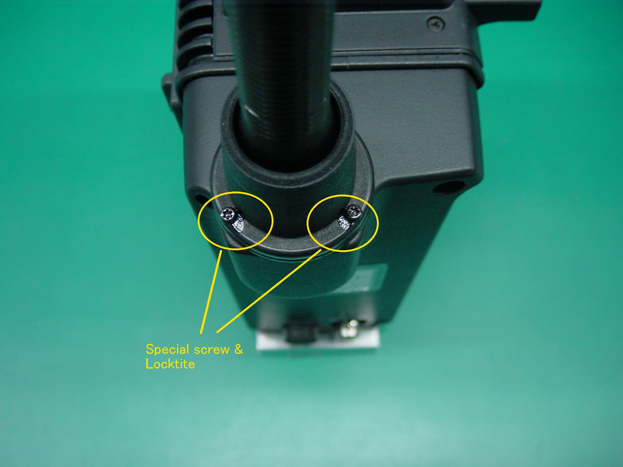
Click to zoom
Application Details
- Equipment Class
- DTS - Digital Transmission System
- Date of Grant
- Nov 05, 2001
- Application Purpose
- Original Equipment
- Date of Application
- Nov 05, 2001
- Equipment Note
- Wireless Transmitter using OFDM modulation
- Frequency Range
- 2406.00000000 - 2474.00000000
- Company
- Sony Group Corporation
- Country
- Japan
Documents & Files
Document Text
Text extracted from the exhibit documents filed with the FCC. Open a document above to read the original.
Users Manual
Compact MPEG Wireless System DLXA-002 OPERATION MANUAL 1 1. Introduction and Features2 1-1. Introduction 1-2. Features 1-2-1. COFDM Transmission 2 12-2. Mobility 2 1-2-3. Fast set up and ease of use 2 1-2-4. MPEG-2 Encoding2 1-2-5. Low Power Consumption2 2. Locations and Function of Parts 3 3. System Configuration Example 6 4. Connections7 5. Menu Operations 8 5-1. Operations 8 5-2 Frequency Table 8 5-3. Operations Flow 9 5-4. Menu Structure10 6. Specifications11 Table of Contents 2 1-1. Introduction The DLXA-002 is a wireless transmitter using Orthogonal Frequency Division Multiplexing (OFDM) modulation technology. The OFDM transmitter transfers data such as pictures, audio and etc. at a rate of 4 to 15 Mbps within 8MHz bandwidth in the Industrial, Scientific and Medical (ISM) band. It consists of MPEG encoder, modulator and RF circuit. The DLXA-002 is docked onto a Sony Camcorder and works only with the signal from Sony Camcorder. The signal of the DLXA-002 is received by the optional antenna and tuner/de-modulator. 1-2. Features 1-2-1. COFDM Transmission Provides very stable RF link Excels in high multi-path environments Significantly outperforms the analog FM system 1-2-2. Mobility Omni-directional Antenna offers more shooting flexibility due to stable RF link 1-2-3. Fast set up and ease of use Dockable to camcorder Compact transmitter Built-in MPEG-2 encoder/COFDM modulator/RF Eliminates triax cable usage 1-2-4. MPEG-2 Encoding High Picture Quality 1-2-5. Low Power Consumption One hour operation using BP-L60A battery 1. Introduction and Features 3 DCLIE ONOFF DC IN Battery attachment section Battery attachment Section Attaches a BP-L60A Battery Pack DC IN (DC power input) connector (XLR type,4-pin, male) The external DC is fed to the camcorder through DLXA-002. The power switch of the camcorder and the DLXA-002 are managed independently. The camcorder works even if the DXLA-002 is turned off. DC-LINE switch This switch turns the power to the DLXA-002 and off. (In side)(Back side) 2.Locations and Functions of Parts 4 (Left view)(Front view) DVB-ASI DVB-ASI For DVB serial bit stream output. Antenna It is unable for user to change the antenna. Fixedantenna 5 LCD display The LCD indicates Status, Setup menu, Items parameters and variables. Cursor buttons While at Menu mode, use these keys for changes. MENU button For selection of the modes. ENTER button To register the selection at the cursor position in each mode. MENU button Cursor buttons Operation panel (Right view) LCD Display ENTER button 6 Li-ion Battery POWER I O DLXA-001 HR Tri nit oron Monitor IF Cable MPEG Decoder Camcorder 3. System Configuration Example DLXA-002 Transmitter (Encoder/Modulator/RF) Tuner and Demodulator Antenna and Receiver Receiver side (Optional) 7 Attaching the DLXA-002 to a Camcorder 1. Attach the DLXA-002 to the back of the Camcorder 2. Tighten the screws. Camcorder DLXA-002 Battery connector Connector 4. Connections 8 5. 1 Operations Turn on The DLXA-002 starts to operate when both DC-LINE switch and a camcorder power switch are turned on. The last status memory When the DLXA-002 is turned off, the status information on the LCD is stored and then stops to work. Save & Load The Configuration Window mode enables to save eight mode combinations as pre-set program, and to load them with ease. 5. 2 Frequency Table 5.Menu Operations 2,4062,408 2,4102,4122,4142,4162,418 2,4202,4222,4242,4262,428 2,4302,4322,4342,4362,438 2,4402,4422,4442,4462,448 2,4502,4522,4542,4562,458 2,4602,4622,4642,4662,468 2,4702,4722,474 In MHz 9 POWER ON 5-3.Operations Flow The LCD indicates Status, Setup menu, Items to be changed and variables. “Operations Flow (5-1) “and “MENU structure (5-2)”explains relations between the modes. MENU Button MENU Button MENU Button ENTER Button RF Video Rate BB STATUS SETUP MENU ITEM VALUE ENC Config. Audio Rate RF Power ENTER Button MENU Button ENTER Button RF BB ENC INIT (Transition) [N]ENTER RF Emission Yes / No ? Config RF Frequency ENTER in case of Value changed [Y] ENTERRF Emission (Transition) MENU Button 10 Menu Window RF Setting Window 1. RF center freq 2. RF emit power 3. RF emission control BB Setting Window 1. Constellation 2. Code rate 3. Guard interval 4. Time interleave ENC Setting Window 1. Profile & level 2. Coded video rate 3. Audio layer 4. Audio comp. mode ch1/2 5. Audio comp. mode ch3/4 6. Coded audio rate ch1/2 7. Coded audio rate ch3/4 8. TS rate 9. PID video 10. PID audio ch1/2 11. PID audio ch3/4 12. PID PMT 13. PID PCR 14. TS byte length 15. TS stream mode Configuration Window 1. Load 2. Save 3. Init 4. LCD 5-4.MENU Structure 11 General DC power voltage DC12V Power consumption 18W Operating temperature0to +40 (+32Fto + 104F) Storage temperature-20to + 60 (-4Fto +140F) Dimensions152(w)207(H) 103(D) Mass1.5kg RF section Frequency2402 ~ 2478 MHz Center Frequency2406 ~ 2474 MHz by 2MHz steps Occupied Bandwidth8MHz Rated RF Power40mW EIRP100mW Connectors External DC INXLR-type4pin, male 11.3 to 18VDC DVB-ASI OUT BNC-type0.8Vp-p 75 Supplied accessories Operation Manual(1) Optional accessories BP-L60/60A/90/90A Battery Pack DC-L1, DC-L90 Battery Adaptor AC-550/550CE, AC-DN1 AC Adaptor Design and specifications are subject to change without notice. 6. Specifications Sony Corporation DLXA-002BSCN B&P Company
Cover Letter(s)
American Telecommunications Certification Body Inc. 6731 Whittier Ave, McLean, VA 22101 October 23, 2001 RE: Sony Corporation FCC ID: AK8DLXA002 After a review of the submitted information, I have a few comments on the above referenced Application. 1) The block diagram and schematics are not clear enough to distinguish. Please provide better copies. 2) The operational description provided is only a brief list of specifications. The operational description should also provide information such as: a) A description of how the device works and circuit descriptions as specified by 2.1033(b)(4), b) information for the antenna in regards to its gain and the antenna connection requirements specified in 15.203. Please be sure to include a clear indication as to whether this device is a transceiver or a transmit only device. It is also desirable to include a list of transmit frequencies the EUT uses. 3) The label on the device should include the statements as specified by 15.19 (a)(3). Please provide an updated version. 4) The Users Manual does include a note regarding the MPE requirements. However, this note should be more obvious so that it easily stands out and catches the attention of the reader. This is easily done by adding an Alert Symbol or a large heading entitled "IMPORTANT NOTE:". 5) The required statements given in 15.21, 15.27, and 15.105 should be added to the users manual as applicable. 6) Section 5 of the users manual implies that the power level of the transmitter may be adjustable. Please confirm that all testing was performed with the transmitter adjusted to maximum output power. 7) The internal photographs should include sufficient views of the overall internal construction and any additional views necessary to define the component placement of the RF module within the chassis (reference 2.1033 (b)(3)). Also, from the photographs provided it is not clear how many shields are actually present on the RF module boards. The photographs of the RF section should include all views necessary to show any shielding components incorporated into the RF section of the device, as well as complete board level views with all shields removed. 8) The power listed on the 731 should be listed in the same manner as the limit set by the FCC (i.e. ERP, EIRP, or conducted). For this application, the power listed on the 731 form should be specified as the maximum conducted power measured (15.3 dBm = 33.9 mW) and not the EIRP measurement. Please provide a corrected copy. 9) For the peak power spectral density test, the FCC desires that the sweep time should be equal to (SPAN/3 kHz) - reference Appendix B of ET Docket No. 96-8 & RM-8435, RM-8608, RM8609. In this case this would be (10 MHz/3kHz) = 3333 seconds. If this is not possible with your equipment, then you should locate and zoom in on the emission peak of the passband of the transmit frequency until your equipment can sweep at the specified rate for the span displayed. 10) For radiated spurious emissions falling within restricted bands, please confirm that the test setup had sufficient dynamic range for measurements made past the second harmonic (above 5 GHz). This is to ensure that the ground floor of the measurement equipment were not above the specified limits. 11) Please provide test data to support that all spurious emissions up to the 10 th harmonic in any 100 kHz bandwidth outside the 2.4 to 2.4835 GHz band are in compliance with the 20 dB requirement. This is best performed by an antenna conducted test with RBW = 100 kHz, VBW > RBW while scanning up to the 10 th harmonics. 12) Plot A24 shows possible higher emissions in the 2.4835-2.500 GHz restricted band than the marker used in the calculations. Please provide more sufficient information to show compliance at this band edge. 13) Please note that “N” style connectors are not permitted under Part 15. Please reference 15.203 Timothy R. Johnson Examining Engineer mailto: [email protected] The items indicated above must be submitted before processing can continue on the above referenced application. Failure to provide the requested information may result in application termination. Correspondence should be considered part of the permanent submission and may be viewed from the Internet after a Grant of Equipment Authorization is issued. Please do not respond to this correspondence using the email reply button. In order for your response to be processed expeditiously, you must submit your documents through the AmericanTCB.com website. Also, please note that partial responses increase processing time and should not be submitted. Any questions about the content of this correspondence should be directed to the sender.
External Photos
External photos <front view> FCC ID:AK8DLXA002 <right view> FCC ID:AK8DLXA002 <left view> FCC ID:AK8DLXA002 <top view> FCC ID:AK8DLXA002 <bottom view> FCC ID:AK8DLXA002 <rear view> FCC ID:AK8DLXA002 <Antenna> FCC ID:AK8DLXA002
ID Label/Location Info
FCC label Bottom view
Internal Photos
Internal photos <top view> FCC ID:AK8DLXA002 <rear view> FCC ID:AK8DLXA002 <top view> FCC ID:AK8DLXA002 <rear view> FCC ID:AK8DLXA002 <rear view> FCC ID:AK8DLXA002
Internal Photos
Internal photos FCC ID:AK8DLXA002 FCC ID:AK8DLXA002 FCC ID:AK8DLXA002 <Broad overview > FCC ID:AK8DLXA002 Internal Photos FCC ID:AK8DLXA002 FCC ID:AK8DLXA002 FCC ID:AK8DLXA002
Operational Description
PLL1 PLL2 MIX1 MIX2 BPF1BPF2 AMP ALC TCXO Freq. Cont. Antenna IF in Emission On/Off LPF #1 #2 #3 #4 #5 #6 RF output RF UNIT Block Diagram •#1: IF signal is already modulated with 16QAM-OFDM, and is input into MIX1 working at 9.14MHz. •#2: The reference frequency for the carrier frequency oscillatesat 12MHz controlled well by TCXO and is distributed to PLL1 and PLL2 circuit. •#4: The PLL2 generates the second local OSC varying from 2126-2194MHz by 2MHz steps. •MIX1 mixes the IF signal #1 and the first local OSC (#3). •#5: BPF1 distills 280MHz bandwidth from MIX1 output. •MIX2 mixes the MIX1 output #5 and the second local OSC (#4). •#6: BPF2 distills approx. 100MHz bandwidth at 2450MHz from MIX2 output. •AMP amplifies RF signal (#6). •LPF suppresses undesired spurious outside of the 2400-2484 MHz band. •ALC feedback-controls RF carrier for constant output. Functional Description of RF UNIT
RF Exposure Info
RF Exposure Statement No. : 22AE0045-YW Applicant: Sony Corporation Type of Equipment: MPEG Transmitter Model No.: DLXA-002 FCC ID: AK8DLXA002 A-PEX International Co., Ltd. YOKOWA LAB. 108 Yokowa-cho, Ise-shi, Mie-ken 516-1106 JAPAN Telephone:int +81 596 39 1485 Facsimile: int +81 596 39 0232 Page 1 FCC Radiation Exposure Statement: Sony Corporation MPEG Transmitter (DLXA-002) complies with FCC radiation exposure requirement specified in the FCC Rules 15.247(b)(4). Notice in Installation Manual FCC Radiation Exposure Statement: This equipment complies with FCC radiation exposure limits set forth for at uncontrolled equipment. This equipment should be installed and operated with minimum distance at least 20cm between the radiator and persons body(excluding extremities : hands, wrists, and feet, legs). RF Exposure Calculations: The following information provides the minimum separation distance for the highest gain antenna provided with the “MPEG Transmitter DLXA-002” as calculated from FCC OET 65 Appendix B, Table (B) Limits for General Population / Uncontrolled Exposure. This calculation is based on the highest EIRP possible from the system, considering maximum power and antenna gain, and considering a 1.0m W/cm^2 uncontrolled exposure limit. The Fires formula used was: S = (P * G) / (4* * r^2) or r = (P * G) / (4 * * S) Where S = 1.0 mW/cm^2 for 2400 MHz P = 33.9 mW (Maximum Conducted Power) G = 1.64(Half wave dipole antenna gain : Converted absolute value) r = Minimum safe distance from antenna (cm) For: MPEG Transmitter DLXA-002 r = 2.1 cm
Test Report
Test report FCC ID: AK8DLXA002 Our reference: 22AE0045-YW Page: 2 of 15 Issued date: 2001-10-15 Revised date: 2001-10-29 Testing Laboratory A-pex International Co., Ltd.Telephone:+81 596 39 1485 108 Yokowa-cho, Ise-shi Mie-ken 516-1106 JAPANFacsimile:+81 596 39 0232 Table of Contents Page 1 GENERAL INFORMATION3 1.1 Tested Methodology4 1.2 Test Facility4 2 PRODUCT DESCRIPTION5 2.1Test system Details5 3 SYSTEM TEST CONFIGURATION6 3.1 Justification6 3.2.Configuration of Tested System6 4 MEASUREMENT UNCERTAINTY7 5 TEST INSTRUMENTS8 6 SUMMARY OF TEST9 6.1 §15.207 Conducted Emissions9 6.2 §15.247(a)(2)6dB Bandwidth9 6.3 §15.247(b) Maximum Peak Out Put Power(Radiated and Conducted)10 6.4 §15.247(c) Out of Band Emissions(Radiated) 11 6.5 §15.247(c) Out of Band Emissions(Conducted) 11 6.6 §15.247(d) Power Density12 Photographs of test setup 13-14 APPENDIX15 Test dataA1toA49 Test report FCC ID: AK8DLXA002 Our reference: 22AE0045-YW Page: 3 of 15 Issued date: 2001-10-15 Revised date: 2001-10-29 Testing Laboratory A-pex International Co., Ltd.Telephone:+81 596 39 1485 108 Yokowa-cho, Ise-shi Mie-ken 516-1106 JAPANFacsimile:+81 596 39 0232 1 GENERAL INFORMATION APPLICANT: Sony Corporation ADDRESS: 4-14-1, Asahi-cho, Atsugi-shi, Kanagawa-ken, 243-0014, Japan Tel: +81-46-230-5602 Fax: +81-46-230-6354 REGULATION(S): FCC Part15 Subpart C, Section 15.247 MODEL NUMBER: DLXA-002 SERIAL NUMBER: 1 KIND OF EQUIPMENT: MPEG Transmitter TESTED DATE: September 28, 29 and October 12, 26, 27 2001 RECEIPT DATE OF SAMPLE : September 28, 2001 REPORT FILE NUMBER: 22AE0045-YW TEST SITE: A-PEX Yokowa No.3 Open Test Sites Test report FCC ID: AK8DLXA002 Our reference: 22AE0045-YW Page: 4 of 15 Issued date: 2001-10-15 Revised date: 2001-10-29 Testing Laboratory A-pex International Co., Ltd.Telephone:+81 596 39 1485 108 Yokowa-cho, Ise-shi Mie-ken 516-1106 JAPANFacsimile:+81 596 39 0232 1.1 Tested Methodology The measurement was performed according to the procedures in FCC/ANSI C63.4(1992). 1.2 Test Facility The open area site measurement facilities used to collect the radiated data are located at 108, Yokowa-cho, Ise-shi, Mie-ken, 516-1106 Japan. These sites have been fully described in reports submitted to the FCC office. No.3 test site has filed to the FCC on September 12, 2000 as number: 90412 and is accepted by Industry Canada on February 19, 1998 as number IC2973-3. Test report FCC ID: AK8DLXA002 Our reference: 22AE0045-YW Page: 5 of 15 Issued date: 2001-10-15 Revised date: 2001-10-29 Testing Laboratory A-pex International Co., Ltd.Telephone:+81 596 39 1485 108 Yokowa-cho, Ise-shi Mie-ken 516-1106 JAPANFacsimile:+81 596 39 0232 2 PRODUCT DESCRIPTION Sony Corporation Model DLXA-002 (referred to as the EUT in this report) is a MPEG Transmitter. The specification is as following : Frequency Characteristics: 2406MHz to 2474MHz Channnel Characteristics: 35channels selectable by 2MHz step and 12MHz spacing. Modulation: 16QAM-OFDM Out Put Power: 100mW(e.i.r.p) Antenna type: Dipole Antenna(Antenna Gain 4.0dBi) Power Supply: DC11.0-18.0V(Battery) ITU Code: 8M00W7WWF 2.1 Test System Details Model FCC ID Description (1)Sony Corporation AK8DLXA002 MPEG Transmitter M/N: DLXA-002 S/N: 1 (2) Sony CorporationN/A Lithium-ion Battery Pack M/N: BP-L60A S/N: 030672 (3) Sony CorporationN/A Digital Camcorder M/N: DNW-7DC12V (29W) S/N: 10140 (4) Sony CorporationN/AAC Adaptor M/N: AC-DN2 S/N: 10088 Test report FCC ID: AK8DLXA002 Our reference: 22AE0045-YW Page: 6 of 15 Issued date: 2001-10-15 Revised date: 2001-10-29 Testing Laboratory A-pex International Co., Ltd.Telephone:+81 596 39 1485 108 Yokowa-cho, Ise-shi Mie-ken 516-1106 JAPANFacsimile:+81 596 39 0232 3 SYSTEM TEST CONFIGURATION 3.1 Justification The system was configured in typical fashion (as a customer would normally use it) for testing. Test mode : Transmitting mode(Out Put Power : High mode) Performed the test about channels Low : 2406MHz Mid : 2442MHz High : 2474MHz 3.2 Configuration of Tested System AC 120V/60Hz Wooden table (4) (2) (1)(3) 75 Terminal * Cabling was taken into consideration and test data was taken under worst case conditions. List of cables used No.NameLength (m)ShieldBackshell MaterialRemark AC Power Cable2.2NPolyvinyl chloride- DC Power Cable2.0YPolyvinyl chloride- Coaxial Cable6.0YMetal- Test report FCC ID: AK8DLXA002 Our reference: 22AE0045-YW Page: 7 of 15 Issued date: 2001-10-15 Revised date: 2001-10-29 Testing Laboratory A-pex International Co., Ltd.Telephone:+81 596 39 1485 108 Yokowa-cho, Ise-shi Mie-ken 516-1106 JAPANFacsimile:+81 596 39 0232 4 Measurement Uncertainty Conducted Emission Test The measurement uncertainty (with a 95% confidence level) for this test was ±2.0dB. The data listed in this test report may exceed the test limit because it does not have enough margin (more than 2.0dB). The data listed in this test report has enough margin, more than 2.0dB. Radiated Emission Test Measurement distance of 3m: The measurement uncertainty (with a 95% confidence level) for this test using Biconical antenna is ±4.4dB. The measurement uncertainty (with a 95% confidence level) for this test using Logperiodic antenna is ±4.8dB. Measurement distance of 10m: The measurement uncertainty (with a 95% confidence level) for this test using Biconical antenna is ±4.4dB. The measurement uncertainty (with a 95% confidence level) for this test using Logperiodic antenna is ±3.2dB. The data listed in this test report may exceed the test limit because it does not have enough margin. The data listed in this test report has enough margin, more than site margin. Test report FCC ID: AK8DLXA002 Our reference: 22AE0045-YW Page: 8 of 15 Issued date: 2001-10-15 Revised date: 2001-10-29 Testing Laboratory A-pex International Co., Ltd.Telephone:+81 596 39 1485 108 Yokowa-cho, Ise-shi Mie-ken 516-1106 JAPANFacsimile:+81 596 39 0232 5 TEST EQUIPMENT USED Name Manufacturer Model Control No. Calibrated Until Pre AmplifierHewlett Packard8447DAF-01March 30, 2002 Pre AmplifierHewlett Pac…
Text truncated - open the document above for the full version.
Test Setup Photos
Test report FCC ID : AK8DLXA002 Our reference : 22AE0045-YW Page : 13 of 15 Issued date : 2001-10-15 Testing Laboratory A-pex International Co., Ltd. Telephone: +81 596 39 1485 108 Yokowa-cho, Ise-shi Mie-ken 516-1106 JAPAN Facsimile: +81 596 39 0232 Photographs of test setup(1) Test report FCC ID : AK8DLXA002 Our reference : 22AE0045-YW Page : 14 of 15 Issued date : 2001-10-15 Testing Laboratory A-pex International Co., Ltd. Telephone: +81 596 39 1485 108 Yokowa-cho, Ise-shi Mie-ken 516-1106 JAPAN Facsimile: +81 596 39 0232 Photographs of test setup(2)
Contact Information
Applicant
Kazuyuki Hori(Chief EMC/RF Compliance Specialist)
Technical Contact
A-Pex International Co., Ltd.Naoki Sakamoto
[email protected]+81-596-39-1485
108 Yokowa-cho · Ise-shi, Mie-ken · Japan
Non-Technical Contact
A-Pex International Co., Ltd.Motomu Kawano
[email protected]+81-596-24-6717
Test Firm
UL Apex Co., Ltd.Toshihiro Ikegami
Technical Specifications
| # | Rule Parts | Frequency Range | Power Output |
|---|---|---|---|
| 1 | 15C | 2.41 GHz - 2.47 GHz | 33.90 mW |
Other Applications from Sony Group Corporation
AK8WW81782
Aug 21, 2026Radio Equipment
Equipment Class
DSS - Part 15 Spread Spectrum TransmitterAK8CFIZCP2
Aug 03, 2026Wireless Controller
Equipment Class
DSS - Part 15 Spread Spectrum TransmitterAK8OEV321MUH
Apr 14, 2026LCD Monitor
Equipment Class
JAD - Part 15 Class A Digital DeviceAK8OEV431MUH
Apr 14, 2026LCD Monitor
Equipment Class
JAD - Part 15 Class A Digital DeviceAK8OEV271MUH
Apr 14, 2026LCD Monitor
Equipment Class
JAD - Part 15 Class A Digital Device