AK8DSCHX30VDigital Still Camera
Sony Group Corporation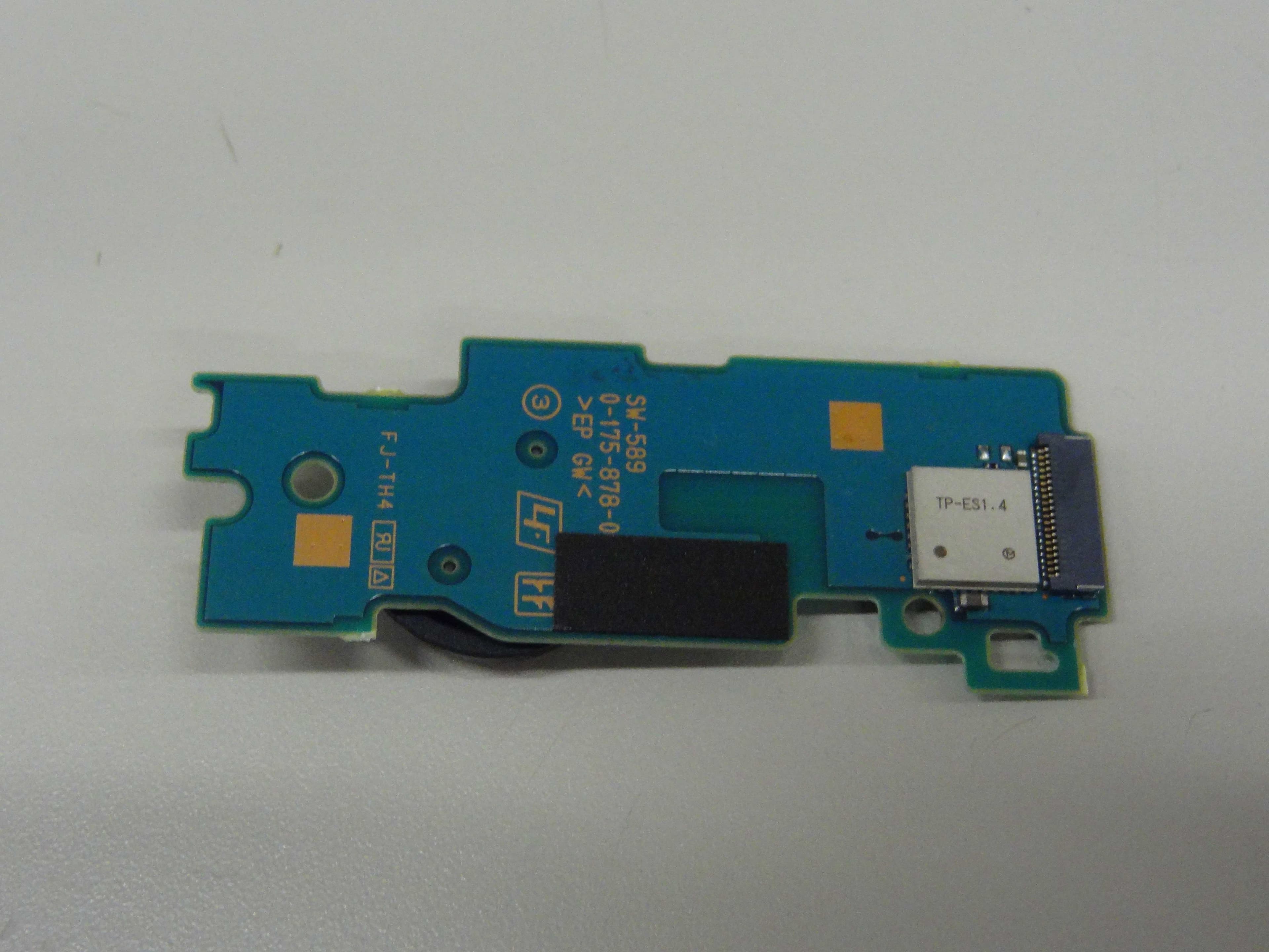
Click to zoom
Application Details
- Equipment Class
- DTS - Digital Transmission System
- Date of Grant
- Mar 03, 2012
- Application Purpose
- Original Equipment
- Date of Application
- Mar 01, 2012
- Equipment Note
- Digital Still Camera
- Frequency Range
- 2412.00000000 - 2462.00000000
- Company
- Sony Group Corporation
- Country
- Japan
Documents & Files
Document Text
Text extracted from the exhibit documents filed with the FCC. Open a document above to read the original.
Users Manual
C:\4419606111\4419606111DSCHX30VCEH\00COV\010 COV.fm master:Right DSC-HX20V/HX30/HX30V 4-419-606-11(1) 4-419-606-11(1) DSC-HX20V/HX30/HX30V Digital Still Camera Instruction Manual 010COV.fm Page 1 Friday, November 11, 2011 4:00 PM DSC-HX20V/HX30/HX30V 4-419-606-11(1) C:\4419606111DSCHX30VCEH\01GB\010GB1.fm master:Left GB 2 The number in parentheses indicates the number of pieces. • Camera (1) • Rechargeable battery pack NP-BG1 (1)/Battery case (1) • Micro USB cable (1) • AC Adaptor AC-UB10/UB10B (1) • Power cord (mains lead) (not supplied in the USA and Canada) (1) • Wrist strap (1) • Instruction Manual (this manual) (1) English Learning more about the camera (“Cyber-shot User Guide”) “Cyber-shot User Guide” is an on-line manual. Refer to it for in-depth instructions on the many functions of the camera. 1Access the Sony support page. http://www.sony.net/SonyInfo/Support/ 2Select your country or region. 3Search for the model name of your camera within the support page. • Check the model name on the bottom of your camera. Checking the supplied items 010GB1.fm Page 2 Friday, November 11, 2011 8:50 PM DSC-HX20V/HX30/HX30V 4-419-606-11(1) C:\4419606111DSCHX30VCEH\01GB\010GB1.fm master:Right GB 3 Owner’s Record The model and serial numbers are located on the bottom. Record the serial number in the space provided below. Refer to these numbers whenever you call your Sony dealer regarding this product. Model No. DSC-HX20V/HX30/HX30V Serial No. _____________________________ Model No. AC-UB10/UB10B Serial No. _____________________________ To reduce fire or shock hazard, do not expose the unit to rain or moisture. IMPORTANT SAFETY INSTRUCTIONS -SAVE THESE INSTRUCTIONS DANGER TO REDUCE THE RISK OF FIRE OR ELECTRIC SHOCK, CAREFULLY FOLLOW THESE INSTRUCTIONS If the shape of the plug does not fit the power outlet, use an attachment plug adaptor of the proper configuration for the power outlet. [Battery pack If the battery pack is mishandled, the battery pack can burst, cause a fire or even chemical burns. Observe the following cautions. • Do not disassemble. • Do not crush and do not expose the battery pack to any shock or force such as hammering, dropping or stepping on it. • Do not short circuit and do not allow metal objects to come into contact with the battery terminals. • Do not expose to high temperature above 60°C (140°F) such as in direct sunlight or in a car parked in the sun. • Do not incinerate or dispose of in fire. • Do not handle damaged or leaking lithium ion batteries. WARNING CAUTION 010GB1.fm Page 3 Friday, November 11, 2011 8:50 PM DSC-HX20V/HX30/HX30V 4-419-606-11(1) C:\4419606111DSCHX30VCEH\01GB\010GB1.fm master:Left GB 4 • Be sure to charge the battery pack using a genuine Sony battery charger or a device that can charge the battery pack. • Keep the battery pack out of the reach of small children. • Keep the battery pack dry. • Replace only with the same or equivalent type recommended by Sony. • Dispose of used battery packs promptly as described in the instructions. [AC Adaptor Connect the AC Adaptor to the nearest wall outlet (wall socket). If some trouble occurs while using the AC Adaptor, immediately shut off the power by disconnecting the plug from the wall outlet (wall socket). The power cord (mains lead), if supplied, is designed specifically for use with this camera only, and should not be used with other electrical equipment. [RECYCLING LITHIUM-ION BATTERIES Lithium-Ion batteries are recyclable. You can help preserve our environment by returning your used rechargeable batteries to the collection and recycling location nearest you. For more information regarding recycling of rechargeable batteries, call toll free 1-800-822-8837, or visit http://www.rbrc.org/ Caution: Do not handle damaged or leaking Lithium-Ion batteries. [Battery pack This device complies with Part 15 of the FCC Rules. Operation is subject to the following two conditions: (1) This device may not cause harmful interference, and (2) this device must accept any interference received, including interference that may cause undesired operation. This Class B digital apparatus complies with Canadian ICES-003. For Customers in the U.S.A. and Canada 010GB1.fm Page 4 Friday, November 11, 2011 8:50 PM DSC-HX20V/HX30/HX30V 4-419-606-11(1) C:\4419606111DSCHX30VCEH\01GB\010GB1.fm master:Right GB 5 UL is an internationally recognized safety organization. The UL Mark on the product means it has been UL Listed. If you have any questions about this product, you may call: Sony Customer Information Center 1-800-222-SONY (7669). The number below is for the FCC related matters only. [Regulatory Information For Customers in the U.S.A. Declaration of Conformity Trade Name: SONY Model No.: DSC-HX20V Responsible Party: Sony Electronics Inc. Address:16530 Via Esprillo, San Diego, CA 92127 U.S.A. Telephone No.: 858-942-2230 This device complies with Part15 of the FCC Rules. Operation is subject to the following two conditions: (1) This device may not cause harmful interference, and (2) this device must accept any interference received, including interference that may cause undesired operation. Declaration of Conformity Trade Name: SONY Model No.: DSC-HX30V Responsible Party: Sony Electronics Inc. Address:16530 Via Esprillo, San Diego, CA 92127 U.S.A. Telephone No.: 858-942-2230 This device complies with Part15 of the FCC Rules. Operation is subject to the following two conditions: (1) This device may not cause harmful interference, and (2) this device must accept any interference received, including interference that may cause undesired operation. 010GB1.fm Page 5 Friday, November 11, 2011 8:50 PM DSC-HX20V/HX30/HX30V 4-419-606-11(1) C:\4419606111DSCHX30VCEH\01GB\010GB1.fm master:Left GB 6 This equipment must not be co-located or operated in conjunction with any other antenna or transmitter. The available scientific evidence does not show that any health problems are associated with using low power wireless devices. There is no proof…
Text truncated - open the document above for the full version.
External Photos
Ext ernal Photoograph Front Rear
ID Label/Location Info
DSC-HX30V Name label position Lens Camera body Name label
Internal Photos
Internal Photograph Front Board (Entire) Rear Board (Entire) RF part RF Antenna
RF Exposure Info
Test report No. : 32BE0317-SH-02-C Page : 1 of 46 Issued date : November 18, 2011 FCC ID : AK8DSCHX30V UL Japan, Inc. Shonan EMC Lab. 1-22-3 Megumigaoka, Hiratsuka-shi, Kanagawa-ken, 259-1220 JAPAN Telephone: +81 463 50 6400 / Facsimile: +81 463 50 6401 SAR TEST REPORT Test Report No.: 32BE0317-SH-02-C Applicant : Sony Corporation Type of Equipment : Digital Still Camera Model No. : DSC-HX30V FCC ID : AK8DSCHX30V Test Standard : FCC 47CFR §2.1093, Supplement C (Edition 01-01) to OET Bulletin 65 Test Result : Complied *.Maximum SAR(1g) Value: 0.29 W/kg (DTS, 2412MHz, IEEE 802.11b, (1Mbps, DBPSK/DSSS)) 1. This test report shall not be reproduced in full or partial, without the written approval of UL Japan, Inc. 2. The results in this report apply only to the sample tested. 3. This sample tested is in compliance with the limits of the above regulation. 4. The test results in this test report are traceable to the national or international standards. 5. This test report must not be used by the customer to claim product certification, approval, or endorsement by any agency of the Federal Government. 6. The opinions and the interpretations to the result of the description in this report are outside scopes where UL Japan has been accredited. Date of test: November 16, 2011 Test engineer: Hiroshi Naka Engineer of WiSE Japan, UL Verification Service Approved by: Toyokazu Imamura Leader of WiSE Japan, UL Verification Service RTL02610 The testing in which "Non-accreditation" is displayed is outside the accreditation scopes in UL Japan. There is no testing item of "Non-accreditation". 13-EM-F0429 Test report No. : 32BE0317-SH-02-C Page : 2 of 46 Issued date : November 18, 2011 FCC ID : AK8DSCHX30V UL Japan, Inc. Shonan EMC Lab. 1-22-3 Megumigaoka, Hiratsuka-shi, Kanagawa-ken, 259-1220 JAPAN Telephone: +81 463 50 6400 / Facsimile: +81 463 50 6401 CONTENTS PAGE SECTION 1: Customer information ....................................................................... 3 SECTION 2: Equipment under test (EUT) ............................................................. 3 SECTION 3: Test specification, procedures and results ........................................ 4 3.1 Test specification ..................................................................................................... 4 3.2 Exposure limit ......................................................................................................... 4 3.3 Procedure and result ................................................................................................. 4 3.4 Test location ............................................................................................................ 4 3.5 Confirmation before SAR testing ............................................................................. 5 3.6 Confirmation after SAR testing ................................................................................ 5 3.7 Measurement procedure ........................................................................................... 6 3.8 Test setup of EUT .................................................................................................... 6 SECTION 4: Operation of EUT during testing ...................................................... 6 4.1 Operating modes for SAR testing ............................................................................. 6 SECTION 5: Uncertainty assessment (SAR measurement) ......................................... 7 SECTION 6: Confirmation before testing .............................................................. 8 6.1 Assessment for the conducted power of EUT ............................................................ 8 SECTION 7: Measurement results .......................................................................... 9 7.1 SAR (Body touch) .................................................................................................... 9 Contents of appendixes APPENDIX 1: Photographs of test setup .................................................................. 10 Appendix 1-1 Photograph of EUT and antenna position ................................................................. 10 Appendix 1-2 EUT and support equipment..................................................................................... 11 Appendix 1-3 Photograph of test setup ........................................................................................... 11 APPENDIX 2: SAR Measurement data .................................................................... 13 Appendix 2-1 Evaluation procedure ............................................................................................... 13 Appendix 2-2 Measurement data .................................................................................................... 14 APPENDIX 3: Test instruments ................................................................................ 20 Appendix 3-1 Equipment used ....................................................................................................... 20 Appendix 3-2 Dosimetry assessment setup ..................................................................................... 21 Appendix 3-3 Configuration and peripherals .................................................................................. 21 Appendix 3-4 System components .................................................................................................. 22 Appendix 3-5 Test system specification .......................................................................................... 23 Appendix 3-6 Simulated tissues composition .................................................................................. 23 Appendix 3-7 Simulated tissues parameter confirmation ................................................................ 24 Appendix 3-8 System check data .................................................................................................... 24 Appendix 3-9 System check meas…
Text truncated - open the document above for the full version.
RF Exposure Info
Test report No. : 32BE0317-SH-02-C Page : 13 of 46 Issued date : November 18, 2011 FCC ID : AK8DSCHX30V UL Japan, Inc. Shonan EMC Lab. 1-22-3 Megumigaoka, Hiratsuka-shi, Kanagawa-ken, 259-1220 JAPAN Telephone: +81 463 50 6400 / Facsimile: +81 463 50 6401 APPENDIX 2: SAR Measurement data Appendix 2-1: Evaluation procedure The SAR evaluation was performed with the following procedure: Step 1: Measurement of the E-field at a fixed location above the central position of flat phantom was used as a reference value for assessing the power drop. Step 2: The SAR distribution at the exposed side of head or body position was measured at a distance of each device from the inner surface of the shell. The area covered the entire dimension of the antenna of EUT and suitable horizontal grid spacing of EUT. Based on these data, the area of the maximum absorption was determined by splines interpolation. Step 3: Around this point found in the Step 2 (area scan), a volume of 30mm(X axis)30mm(Y axis)30mm(Z axis) was assessed by measuring 777 points under 3GHz. And for any secondary peaks found in the Step2 which are within 2dB of maximum peak and not with this Step3 (Zoom scan) is repeated. On the basis of this data set, the spatial peak SAR value was evaluated under the following procedure: (1) The data at the surface were extrapolated, since the center of the dipoles is 1mm away from the tip of the probe and the distance between the surface and the lowest measuring point is 2mm. The extrapolation was based on a least square algorithm [4]. A polynomial of the fourth order was calculated through the points in z-axes. This polynomial was then used to evaluate the points between the surface and the probe tip. (2) The maximum interpolated value was searched with a straightforward algorithm. Around this maximum the SAR values averaged over the spatial volumes (1g or 10g) were computed by the 3D-Spline interpolation algorithm. The 3D-Spline is composed of three one-dimensional splines with the “Not a knot"-condition (in x, y and z-directions) [4], [5]. The volume was integrated with the trapezoidal-algorithm. One thousand points (101010) were interpolated to calculate the average. (3) All neighboring volumes were evaluated until no neighboring volume with a higher average value was found. Step 4: Re-measurement of the E-field at the same location as in Step 1 for the assessment of the power drift. Step 5: Repeat Step 1-Step 4 with other condition or/and setup of EUT. Test report No. : 32BE0317-SH-02-C Page : 14 of 46 Issued date : November 18, 2011 FCC ID : AK8DSCHX30V UL Japan, Inc. Shonan EMC Lab. 1-22-3 Megumigaoka, Hiratsuka-shi, Kanagawa-ken, 259-1220 JAPAN Telephone: +81 463 50 6400 / Facsimile: +81 463 50 6401 Appendix 2-2: Measurement data Step 1: Worst position search Step 1-1: Right-touch (separation distance=0mm), 2462MHz, 11b(1Mbps), Battery=#1 EUT: Digital Still Camera; Type: DSC-HX30V; Serial: 17 Communication System: 802.11b(1Mbps,DBPSK/DSSS); Frequency: 2462 MHz; Crest Factor: 1.0 Medium: MSL2450; Medium parameters used (22.7deg.C.): f = 2462 MHz; σ = 2 S/m; ε r = 50.6; ρ = 1000 kg/m 3 DASY4 Configuration: - Probe: EX3DV4 - SN3679; ConvF(7.34, 7.34, 7.34); Calibrated: 2011/05/19 - Sensor-Surface: 2mm (Mechanical Surface Detection) - Electronics: DAE4 Sn626; Calibrated: 2011/02/10 - Phantom: ELI 4.0; Type: QDOVA001BA; Serial: 1059; Phantom section: Flat Section - Measurement SW: DASY4, V4.7 Build 80; Postprocessing SW: SEMCAD, V1.8 Build 184 r1,right&touch(d0mm),11b(1m),m2462(11)/ Area Scan:75x60,15 (6x5x1): Measurement grid: dx=15mm, dy=15mm; Maximum value of SAR (measured) = 0.033 mW/g Area Scan:75x60,15 (51x41x1): Measurement grid: dx=15mm, dy=15mm; Maximum value of SAR (interpolated) = 0.052 mW/g Zoom Scan:30x30x30,5 (7x7x7)/Cube 0: Measurement grid: dx=5mm, dy=5mm, dz=5mm; Reference Value = 3.60 V/m; Power Drift = 0.20 dB, Maximum value of SAR (measured) = 0.057 mW/g Peak SAR (extrapolated) = 0.086 W/kg SAR(1 g) = 0.032 mW/g; SAR(10 g) = 0.014 mW/g [Antenna position (Transparency)] [Area scan result(Interpolated, w/Zoom scan cube line)] Additional information: *.position: distance of EUT to phantom: 0mm (2mm to liquid), liquid depth: 154mm *.ambient: 23.3deg..C. / 40%RH; liquid temperature: (before) 22.5 deg.C. /(after) 22.5 deg.C. *.white cubic: zoom scan area, red big cubic: SAR(10g ), red small cubic: SAR(1g) *.Tested by: Hiroshi Naka / Tested place:No.7 shielded room / Date tested: November 16, 2011 Test report No. : 32BE0317-SH-02-C Page : 15 of 46 Issued date : November 18, 2011 FCC ID : AK8DSCHX30V UL Japan, Inc. Shonan EMC Lab. 1-22-3 Megumigaoka, Hiratsuka-shi, Kanagawa-ken, 259-1220 JAPAN Telephone: +81 463 50 6400 / Facsimile: +81 463 50 6401 Appendix 2-2: Measurement data (cont’d) Step 1: Worst position search (cont’d) Step 1-2: Right-rear-touch (separation distance=0mm), 2462MHz, 11b(1Mbps), Battery=#3 EUT: Digital Still Camera; Type: DSC-HX30V; Serial: 17 Communication System: 802.11b(1Mbps,DBPSK/DSSS); Frequency: 2462 MHz; Crest Factor: 1.0 Medium: MSL2450; Medium parameters used (22.7deg.C.): f = 2462 MHz; σ = 2 S/m; ε r = 50.6; ρ = 1000 kg/m 3 DASY4 Configuration: - Probe: EX3DV4 - SN3679; ConvF(7.34, 7.34, 7.34); Calibrated: 2011/05/19 - Sensor-Surface: 2mm (Mechanical Surface Detection) - Electronics: DAE4 Sn626; Calibrated: 2011/02/10 - Phantom: ELI 4.0; Type: QDOVA001BA; Serial: 1059; Phantom section: Flat Section - Measurement SW: DASY4, V4.7 Build 80; Postprocessing SW: SEMCAD, V1.8 Build 184 r6,right-rear-naname&touch(d0mm),11b(1m),m2462(11)/ Area Scan:75x60,15 (6x5x1): Measurement grid: dx=15mm, dy=15mm; Maximum value of SAR (measured) = 0.099 mW/g Area Scan:75x60,15 (51x41x1): Measurement grid: dx=15mm, dy=15mm; Maximum value of SAR (interpolated) = 0.102 mW/g Zoom Scan:30x30x30,5 (7x7x7)/Cube 0: Measurement grid: dx=5mm, dy=5mm, dz=5mm; Reference Value = 7.30 V/m; Power Drift = -0.199 dB, Maximum value of SAR (measured) = 0.201 mW/g Peak SAR (extrapolated) = 0.…
Text truncated - open the document above for the full version.
Test Report
Test report No. : 32BE0317-SH-02-A-R1 Page : 1 of 69 Issued date : February 14, 2012 FCC ID : AK8DSCHX30V UL Japan, Inc. Shonan EMC Lab. 1-22-3 Megumigaoka, Hiratsuka-shi, Kanagawa-ken, 259-1220 JAPAN Telephone : +81 463 50 6400 Facsimile : +81 463 50 6401 RADIO TEST REPORT Test Report No. : 32BE0317-SH-02-A-R1 Applicant : Sony Corporation. Type of Equipment : Digital Still Camera Model No. : DSC-HX30V FCC ID : AK8DSCHX30V Test regulation : FCC Part15 Subpart C: 2011 Test result : Complied 1. This test report shall not be reproduced in full or partial, without the written approval of UL Japan, Inc. 2. The results in this report apply only to the sample tested. 3. This sample tested is in compliance with the limits of the above regulation. 4. The test results in this test report are traceable to the national or international standards. 5. This test report must not be used by the customer to claim product certification, approval, or endorsement by any agency of the Federal Government. 6. The opinions and the interpretations to the result of the description in this report are outside scopes where UL Japan has been accredited. 7. This report is a revised version of 32BE0317-SH-02-A. 32BE0317-SH-02-A is replaced with this report. Date of test: October 22 to 27, 2011 Representative test engineer: ______________________________ Hikaru Shirasawa Engineer of WiSE Japan, UL Verification Service Approved by : ______________________________ Ichiro Isozaki Leader of WiSE Japan, UL Verification Service RTL02610 The testing in which "Non-accreditation" is displayed is outside the accreditation scopes in UL Japan. There is no testing item of "Non-accreditation". 13-EM-F0429 Test report No. : 32BE0317-SH-02-A-R1 Page : 2 of 69 Issued date : February 14, 2012 FCC ID : AK8DSCHX30V UL Japan, Inc. Shonan EMC Lab. 1-22-3 Megumigaoka, Hiratsuka-shi, Kanagawa-ken, 259-1220 JAPAN Telephone : +81 463 50 6400 Facsimile : +81 463 50 6401 Contents Page SECTION 1: Customer information ..................................................................................... 3 SECTION 2: Equipment under test (E.U.T.) ....................................................................... 3 SECTION 3: Test specification, procedures & results ......................................................... 4 SECTION 4: Operation of E.U.T. during testing ................................................................. 6 SECTION 5: Conducted emission ......................................................................................... 7 SECTION 6: 6dB bandwidth & Occupied bandwidth (99%) ............................................. 7 SECTION 7: Maximum peak output power ......................................................................... 8 SECTION 8: Spurious emission (Antenna port conducted) ................................................ 8 SECTION 9: Radiated emission ............................................................................................ 9 SECTION 10: Peak Power density ...................................................................................... 10 Contents of APPENDIXES ................................................................................................... 11 APPENDIX 1: Data of Radio tests ...................................................................................... 12 APPENDIX 2: Test instruments .......................................................................................... 66 APPENDIX 3: Photographs of test setup ............................................................................ 67 Test report No. : 32BE0317-SH-02-A-R1 Page : 3 of 69 Issued date : February 14, 2012 FCC ID : AK8DSCHX30V UL Japan, Inc. Shonan EMC Lab. 1-22-3 Megumigaoka, Hiratsuka-shi, Kanagawa-ken, 259-1220 JAPAN Telephone : +81 463 50 6400 Facsimile : +81 463 50 6401 SECTION 1: Customer information Company Name : Sony Corporation Brand Name : SONY Address : Shinagawa INTERCITY C Tower 2-15-3, Konan Minato-ku, Tokyo, 108-6201 Japan Telephone Number : +81- 3-5769-5640 Facsimile Number : +81- 3-5769-5996 Contact Person : Keizo Tsuneki SECTION 2: Equipment under test (E.U.T.) 2.1 Identification of E.U.T. Type of Equipment : Digital Still Camera Model No. : DSC-HX30V Serial No. : Refer to 4.2 in this report. Rating : AC adaptor: AC 120V / 60Hz (for testing) AC 100V – 240V / 50Hz, 60Hz (for EUT specification) (EUT’s specification: DC 3.6V) Receipt Date of Sample : October 21, 2011 Country of Mass-production : Japan or Thailand Condition of EUT : Engineer prototype (Not for Sale: This sample is equivalent to mass-produced items.) Modification of EUT : No modification by the test lab. 2.2 Product description Model: DSC-HX30V (referred to as the EUT in this report) is a Digital Still Camera. Clock frequency(ies) in the system : 26MHz; WLAN part 16.368MHz; GPS part Radio specification Equipment type : Transceiver Frequency of operation : 2412-2462MHz (IEEE 802.11b, 11g, 11n-HT20) Bandwidth & channel spacing: Bandwidth : 20MHz Channel spacing : 5MHz Type of modulation : DSSS (IEEE 802.11b) OFDM (IEEE 802.11g/n) Antenna type : Chip antenna Antenna connector type : None Antenna gain with cable loss : -4.93dBi ITU code : D1D, G1D Operation temperature range : 0 to 40 deg.C. FCC Part15.31 (e) The RF part is provided with stable power supply DC 3.3V and DC 1.8V from the camera, therefore, the equipment complies power supply regulation. FCC Part15.203 The antenna is not removable from the EUT. Therefore, the equipment complies with the antenna requirement of Section 15.203. Test report No. : 32BE0317-SH-02-A-R1 Page : 4 of 69 Issued date : February 14, 2012 FCC ID : AK8DSCHX30V UL Japan, Inc. Shonan EMC Lab. 1-22-3 Megumigaoka, Hiratsuka-shi, Kanagawa-ken, 259-1220 JAPAN Telephone : +81 463 50 6400 Facsimile : +81 463 50 6401 SECTION 3: Test specification, procedures & results 3.1 Test specification Test specification : FCC Part 15 Subpart C: 2011, final revised on July 8, 2011 and effective …
Text truncated - open the document above for the full version.
Test Setup Photos
Test report No. : 32BE0317-SH-02-A-R1 UL Japan, Inc. Shonan EMC Lab. 1-22-3 Megumigaoka, Hiratsuka-shi, Kanagawa-ken, 259-1220 JAPAN Telephone : +81 463 50 6400 Facsimile : +81 463 50 6401 APPENDIX 3: Photographs of test setup Conducted emission Page 67 of 69 Test report No. : 32BE0317-SH-02-A-R1 UL Japan, Inc. Shonan EMC Lab. 1-22-3 Megumigaoka, Hiratsuka-shi, Kanagawa-ken, 259-1220 JAPAN Telephone : +81 463 50 6400 Facsimile : +81 463 50 6401 Radiated emission (below 1GHz) (above 1GHz) Page 68 of 69 Test report No. : 32BE0317-SH-02-A-R1 UL Japan, Inc. Shonan EMC Lab. 1-22-3 Megumigaoka, Hiratsuka-shi, Kanagawa-ken, 259-1220 JAPAN Telephone : +81 463 50 6400 Facsimile : +81 463 50 6401 Pre-check of the worst position X-axis Y-axis Z-axis Page 69 of 69
Test Setup Photos
Test report No. : 32BE0317-SH-02-C Page : 10 of 46 Issued date : November 18, 2011 FCC ID : AK8DSCHX30V UL Japan, Inc. Shonan EMC Lab. 1-22-3 Megumigaoka, Hiratsuka-shi, Kanagawa-ken, 259-1220 JAPAN Telephone: +81 463 50 6400 / Facsimile: +81 463 50 6401 APPENDIX 1: Photographs of EUT and SAR test setup Appendix 1-1: Photograph of EUT and antenna position Antenna Top 60mm Bottom Antenna 32mm Rear(LCD) Rear (LCD) 100mm 20mm 3mm 32mm Top Rear (LCD) Right Bottom Front (Lens) Left Test report No. : 32BE0317-SH-02-C Page : 11 of 46 Issued date : November 18, 2011 FCC ID : AK8DSCHX30V UL Japan, Inc. Shonan EMC Lab. 1-22-3 Megumigaoka, Hiratsuka-shi, Kanagawa-ken, 259-1220 JAPAN Telephone: +81 463 50 6400 / Facsimile: +81 463 50 6401 Appendix 1-2: EUT and support equipment Description of EUT and Support Equipment No. Item Model numberSerial numberManufacturerRemark A Digital Still Camera DSC-HX30V 17SONYEUT. B1 Battery Pack (Li-ion, 3.6V, 910mAh, 3.4Wh) NP-BG1 01 SONY Accessory of EUT, Battery No. #1. B2 02 Accessory of EUT, Battery No. #2. B3 03Accessory of EUT, Battery No. #3. C AC adaptor (for battery charging) AC-UB10 01 SONY Support equipment. List of cables used No. Name Length(m)ShieldShell typeRemark USB cable 0.95ShieldedMetal(For the battery charging operation.) Appendix 1-3: Photograph of test setup Position Setup photograph 1 Setup photograph 2 Setup photograph 3 Right -touch Right-rear -touch Front -touch B1 B2 A: EUT B3 SAR test B1 B2 B3 C Battery charging A: EUT Test report No. : 32BE0317-SH-02-C Page : 12 of 46 Issued date : November 18, 2011 FCC ID : AK8DSCHX30V UL Japan, Inc. Shonan EMC Lab. 1-22-3 Megumigaoka, Hiratsuka-shi, Kanagawa-ken, 259-1220 JAPAN Telephone: +81 463 50 6400 / Facsimile: +81 463 50 6401 Appendix 1-3: Photograph of test setup (cont’d) Position Setup photograph 1 Setup photograph 2 Setup photograph 3 Top -touch Bottom -touch Rear -touch Rear (5mm separation distance)
Contact Information
Applicant
Kazuyuki Hori(Chief EMC/RF Compliance Specialist)
Technical Contact
UL Japan, Inc.Ichiro Isozaki
[email protected]81-463-50-6400
1-22-3 Megumigaoka, Hiratsuka-shi · Kanagawa · Japan
Test Firm
UL Japan, Inc. Shonan EMC EMC Lab.Tetsuya Hashimoto
Technical Specifications
| # | Rule Parts | Frequency Range | Power Output |
|---|---|---|---|
| 2 | 15C | 2.41 GHz - 2.46 GHz | 41.00 mW |
Other Applications from Sony Group Corporation
AK8WW81782
Aug 21, 2026Radio Equipment
Equipment Class
DSS - Part 15 Spread Spectrum TransmitterAK8CFIZCP2
Aug 03, 2026Wireless Controller
Equipment Class
DSS - Part 15 Spread Spectrum TransmitterAK8OEV321MUH
Apr 14, 2026LCD Monitor
Equipment Class
JAD - Part 15 Class A Digital DeviceAK8OEV431MUH
Apr 14, 2026LCD Monitor
Equipment Class
JAD - Part 15 Class A Digital DeviceAK8OEV271MUH
Apr 14, 2026LCD Monitor
Equipment Class
JAD - Part 15 Class A Digital Device