AK8DTPT1000ABDevelopment Tool
Sony Group Corporation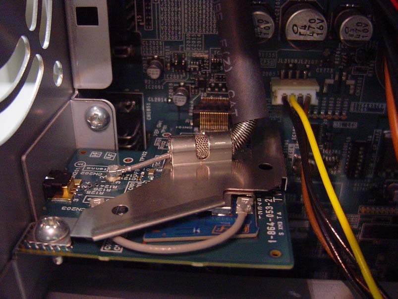
Click to zoom
Application Details
- Equipment Class
- DTS - Digital Transmission System
- Date of Grant
- Oct 24, 2008
- Application Purpose
- Original Equipment
- Date of Application
- Oct 23, 2008
- Equipment Note
- Development Tool
- Frequency Range
- 2412.00000000 - 2462.00000000
- Company
- Sony Group Corporation
- Country
- Japan
Documents & Files
Document Text
Text extracted from the exhibit documents filed with the FCC. Open a document above to read the original.
Users Manual
DTP-T2000A 4-121-350-11(1) Instruction manual SCE CONFIDENTIAL DTP-T2000A Development Tool This manual contains safety precautions for the prevention of accidents, and instructions for the use and handling of this product. Read this manual carefully and use the product in a safe manner. After reading the manual, store it in an accessible location for future reference. 4-121-350-11(1) 2 DTP-T2000A 4-121-350-11(1) WARNING WARNING To avoid electrical shock, do not open the cabinet. Refer servicing to qualified personnel only. Use the supplied AC adaptor only. If you use other types, it may cause fire, electrical shocks or a malfunction. Laser specifications UMD TM Wave length:655-665 nm Power:max 0.28 mW Type:Semiconductor, continuous DVD-ROM Wave length:640-660 nm (DVD) 775-805 nm (CD) Power:max 0.3 mW (DVD) 0.23 mW (CD) Type:Semiconductor, continuous CAUTION Use of controls or adjustments or performance of procedures other than those specified herein may result in hazardous radiation exposure. The use of optical instruments with this product will increase eye hazard. As the laser beams used in the DVD- ROM and UMD™ drives are harmful to eyes, do not attempt to disassemble the cabinet. Refer servicing to qualified personnel only. This label is located on the DVD-ROM laser protective housing inside the enclosure. CLASS 1 LASER PRODUCT LASER KLASE 1 LUOKAN 1 LASER LAITE KLASS 1 LASERAPPARAT This appliance is classified as a CLASS 1 LASER product under IEC60825-1: 2001. The CLASS 1 LASER product marking is located on the side of the product. For customers in the U.S.A. NOTE: This equipment has been tested and found to comply with the limits for a Class A digital device, pursuant to Part 15 of the FCC Rules. These limits are designed to provide reasonable protection against harmful interference when the equipment is operated in a commercial enviroment. This equipment generates, uses, and can radiate radio frequency energy and, if not installed and used in accordance with the instructions, may cause harmful interference to radio communications. Operation of this equipment in a residential area is likely to cause harmful interference in which case the user will be required to correct the interference at his own expense. You are cautioned that any changes or modifications not expressly approved in this manual could void your authority to operate this equipment. About the lithium coin memory back-up battery The lithium coin memory back-up battery inside this product contains Perchlorate. The following statement is required by the State of California, USA: Perchlorate Material - special handling may apply, See http://www.dtsc.ca.gov/hazardouswaste/perchlorate For customers in the U.S.A. and Canada This Class A digital apparatus complies with Canadian ICES-003. This device complies with Part 15 of the FCC Rules and RSS-Gen of IC Rules. Operation is subject to the following two conditions: (1) this device may not cause harmful interference, and (2) this device must accept any interference received, including interference that may cause undesired operation of this device. This equipment complies with FCC/IC radiation exposure limits set forth for uncontrolled equipment and meets the FCC radio frequency (RF) Exposure Guidelines in Supplement C to OET65 and RSS-102 of the IC radio frequency (RF) Exposure rules. This equipment should be installed and operated with at least 20 cm (8 in) and more between the radiator and person's body (excluding extremities: hands, wrists, feet and legs). This transmitter must not be co-located or operated in conjunction with any other antenna or transmitter. Pour les utilisateurs aux États-Unis et au Canada Cet appareil numérique de la classe A est conforme à la norme NMB-003 du Canada. Cet appareil est conforme aux stipulations de l'article 15 des règlements de la FCC et RSS-Gen des règles IC. Son opération est sous réserve des deux conditions suivantes : (1) cet appareil ne peut pas causer de brouillage préjudiciable et (2) cet appareil doit accepter le brouillage préjudiciable reçu, y compris un brouillage qui pourrait causer son fonctionnement irrégulier. Cet équipement est conforme aux limites d'exposition aux radiofréquences IC établies pour un environnement non contrôlé et se conforme aux exigences de conformité pour l'exposition aux RF IC, dans le supplément C à OET65 et RSS-102. Cet équipement doit être installé et opéré à au moins 20 cm (8 po.) d'écart entre le radiateur et la personne physique (extrémités du corps non prises en compte : mains, poignets, pieds et jambes). Ce transmetteur ne doit pas être utilisé conjointement ou placé avec tout autre transmetteur ou antenne. WARNING 3 DTP-T2000A 4-121-350-11(1) For your protection, please read these safety instructions completely before operating the appliance, and keep this manual for future reference. Carefully observe all warnings, precautions and instructions on the appliance, or those described in the instruction manual and adhere to them. USE Power sources This unit should be operated only from the type of power source indicated on the marking label. If you are not sure of the type of electrical power supplied to your home, consult your dealer or local power company. For those units designed to operate from battery power, or other sources, refer to the operating instructions. Overloading Do not overload wall outlets, extension cords or convenience receptacles beyond their capacity, since this can result in fire or electric shock. Liquid and foreign objects Never push objects of any kind into the unit through openings as they may touch dangerous voltage points or short out parts that could result in a fire or electric shock. Never spill liquid of any kind on the unit. Attachments Use only attachments recommended by the manufacturer. Other attachments may cause hazards. Cleaning Unplug the unit from the wall outlet before cleaning or polishing it. Do not use liquid cleaners or aerosol cleaners. Use a cloth l…
Text truncated - open the document above for the full version.
Internal Photos
Internal Photo Sony Corporation DEVELOPMENT TOOL [Model: DTP-T1000A B] FCC ID: AK8DTPT1000AB IC: 409B-DTPT1000AB Overview RF Module position 1 Internal Photo Sony Corporation DEVELOPMENT TOOL [Model: DTP-T1000A B] FCC ID: AK8DTPT1000AB IC: 409B-DTPT1000AB RF Module position 2 RF Module with Shield (Front) Internal Photo Sony Corporation DEVELOPMENT TOOL [Model: DTP-T1000A B] FCC ID: AK8DTPT1000AB IC: 409B-DTPT1000AB RF Module without Shield (Front) RF Module (Rear)
Test Report
Test report No. : 29AE0044-HO-01-A Page : 20 of 44 Issued date : October 17, 2008 FCC ID : AK8DTPT1000AB UL Japan, Inc. Head Office EMC Lab. 4383-326 Asama-cho, Ise-shi, Mie-ken 516-0021 JAPAN Telephone : +81 596 24 8116 Facsimile : +81 596 24 8124 APPENDIX 2: Data of EMI test Conducted Emission Tx, Ch: Low DATA OF CONDUCTED EMISSION TEST UL Japan, Inc. Head Office EMC Lab. No.3 Semi Anechoic Chamber Date : 2008/10/16 Company : Sony Computer Entertainment Inc. Report No. : 29AE0044-HO-01 Kind of EUT : Development Tool Power : AC120V / 60Hz Model No. : DTP-T1000A B Temp./Humi. : 23deg.C / 53% Serial No. : SJ0006904 Operator : Kazuya Yoshioka Mode / Remarks : WLAN 11b Tx 2412MHz LIMIT : FCC15.207 QP FCC15.207 AV CHART:WITH FACTOR,Peak hold data. CALCURATION:RESULT[dBuV]=READING[dBuV]+C.F[dB](LISN LOSS+CABLE LOSS) Except for the above table: adequate margin data below the limits. Frequency[Hz] [dBuV]<< QP/AV DATA >> L:QP:AV N:QP:AV .15M30M.2M.3M.5M.7M1M2M3M5M7M10M20M 0 10 20 30 40 50 60 70 80 Frequency Reading LevelReading LevelCorr.ResultsResultsLimitLimitMarginMargin PhaseComment Frequency QPAVFactorQPAVQPAVQPAVPhaseComment [MHz][dBuV][dBuV][dB][dBuV][dBuV][dBuV][dBuV][dB][dB] PhaseComment 0.1629443.432.40.343.732.765.355.321.622.6N 0.3289046.528.00.346.828.359.549.512.721.2N 0.5809843.841.00.344.141.356.046.011.94.7N 2.4356233.819.10.434.219.556.046.021.826.5N 2.8507334.826.30.535.326.856.046.020.719.2N 3.3345438.635.10.639.235.756.046.016.810.3N 4.5467444.741.00.645.341.656.046.010.74.4N 7.0510039.534.10.840.334.960.050.019.715.1N 0.1590551.034.00.351.334.365.555.514.221.2L 0.3354037.126.00.337.426.359.349.321.923.0L 0.5797042.941.30.343.241.656.046.012.84.4L 2.4530934.820.00.435.220.456.046.020.825.6L 2.9012435.726.40.536.226.956.046.019.819.1L 3.2595636.726.20.637.326.856.046.018.719.2L 4.5473044.340.80.644.941.456.046.011.14.6L 7.0813038.833.30.839.634.160.050.020.415.9L *The test result is round off to one or two decimal places, so some differences might be observed. Test report No. : 29AE0044-HO-01-A Page : 21 of 44 Issued date : October 17, 2008 FCC ID : AK8DTPT1000AB UL Japan, Inc. Head Office EMC Lab. 4383-326 Asama-cho, Ise-shi, Mie-ken 516-0021 JAPAN Telephone : +81 596 24 8116 Facsimile : +81 596 24 8124 Conducted Emission Tx, Ch: Mid DATA OF CONDUCTED EMISSION TEST UL Japan, Inc. Head Office EMC Lab. No.3 Semi Anechoic Chamber Date : 2008/10/16 Company : Sony Computer Entertainment Inc. Report No. : 29AE0044-HO-01 Kind of EUT : Development Tool Power : AC120V / 60Hz Model No. : DTP-T1000A B Temp./Humi. : 23deg.C / 53% Serial No. : SJ0006904 Operator : Kazuya Yoshioka Mode / Remarks : WLAN 11b Tx 2437MHz LIMIT : FCC15.207 QP FCC15.207 AV CHART:WITH FACTOR,Peak hold data. CALCURATION:RESULT[dBuV]=READING[dBuV]+C.F[dB](LISN LOSS+CABLE LOSS) Except for the above table: adequate margin data below the limits. Frequency[Hz] [dBuV]<< PEAK DATA >> N:PEAK .15M30M.2M.3M.5M.7M1M2M3M5M7M10M20M 0 10 20 30 40 50 60 70 80 Frequency[Hz] [dBuV]<< PEAK DATA >> L:PEAK .15M30M.2M.3M.5M.7M1M2M3M5M7M10M20M 0 10 20 30 40 50 60 70 80 Test report No. : 29AE0044-HO-01-A Page : 22 of 44 Issued date : October 17, 2008 FCC ID : AK8DTPT1000AB UL Japan, Inc. Head Office EMC Lab. 4383-326 Asama-cho, Ise-shi, Mie-ken 516-0021 JAPAN Telephone : +81 596 24 8116 Facsimile : +81 596 24 8124 Conducted Emission Tx, Ch: High DATA OF CONDUCTED EMISSION TEST UL Japan, Inc. Head Office EMC Lab. No.3 Semi Anechoic Chamber Date : 2008/10/16 Company : Sony Computer Entertainment Inc. Report No. : 29AE0044-HO-01 Kind of EUT : Development Tool Power : AC120V / 60Hz Model No. : DTP-T1000A B Temp./Humi. : 23deg.C / 53% Serial No. : SJ0006904 Operator : Kazuya Yoshioka Mode / Remarks : WLAN 11b Tx 2462MHz LIMIT : FCC15.207 QP FCC15.207 AV CHART:WITH FACTOR,Peak hold data. CALCURATION:RESULT[dBuV]=READING[dBuV]+C.F[dB](LISN LOSS+CABLE LOSS) Except for the above table: adequate margin data below the limits. Frequency[Hz] [dBuV]<< PEAK DATA >> N:PEAK .15M30M.2M.3M.5M.7M1M2M3M5M7M10M20M 0 10 20 30 40 50 60 70 80 Frequency[Hz] [dBuV]<< PEAK DATA >> L:PEAK .15M30M.2M.3M.5M.7M1M2M3M5M7M10M20M 0 10 20 30 40 50 60 70 80 Test report No. : 29AE0044-HO-01-A Page : 23 of 44 Issued date : October 17, 2008 FCC ID : AK8DTPT1000AB UL Japan, Inc. Head Office EMC Lab. 4383-326 Asama-cho, Ise-shi, Mie-ken 516-0021 JAPAN Telephone : +81 596 24 8116 Facsimile : +81 596 24 8124 Conducted Emission Rx, Ch: Mid DATA OF CONDUCTED EMISSION TEST UL Japan, Inc. Head Office EMC Lab. No.3 Semi Anechoic Chamber Date : 2008/10/16 Company : Sony Computer Entertainment Inc. Report No. : 29AE0044-HO-01 Kind of EUT : Development Tool Power : AC120V / 60Hz Model No. : DTP-T1000A B Temp./Humi. : 23deg.C / 53% Serial No. : SJ0006904 Operator : Kazuya Yoshioka Mode / Remarks : WLAN 11b Rx 2437MHz LIMIT : FCC15.207 QP FCC15.207 AV CHART:WITH FACTOR,Peak hold data. CALCURATION:RESULT[dBuV]=READING[dBuV]+C.F[dB](LISN LOSS+CABLE LOSS) Except for the above table: adequate margin data below the limits. Frequency[Hz] [dBuV]<< QP/AV DATA >> L:QP:AV N:QP:AV .15M30M.2M.3M.5M.7M1M2M3M5M7M10M20M 0 10 20 30 40 50 60 70 80 Frequency Reading LevelReading LevelCorr.ResultsResultsLimitLimitMarginMargin PhaseComment Frequency QPAVFactorQPAVQPAVQPAVPhaseComment [MHz][dBuV][dBuV][dB][dBuV][dBuV][dBuV][dBuV][dB][dB] PhaseComment 0.1592440.129.90.340.430.265.555.525.125.3N 0.3359044.526.20.344.826.559.349.314.522.8N 0.5838343.041.30.343.341.656.046.012.74.5N 2.2629034.322.00.434.722.456.046.021.323.6N 2.4241032.926.30.433.326.756.046.022.719.3N 3.1126434.726.40.535.226.956.046.020.819.1N 4.5485044.640.70.645.241.356.046.010.84.7N 7.1759339.533.90.840.334.760.050.019.715.3N 0.1583549.031.60.349.331.965.655.616.323.7L 0.3322035.225.90.335.526.259.449.423.923.2L 0.5844543.141.40.343.441.756.046.012.64.3L 2.2574036.223.20.436.623.656.046.019.422.4L 2.4234036.026.40.436.426.856.046.019.619.2L 3.1170136.426.70.536.927.256.046.019.118.8L 4.5465344.340.60.644.941.256.046.011.14.8L 7.2156238.032.1…
Text truncated - open the document above for the full version.
Contact Information
Applicant
Kazuyuki Hori(Chief EMC/RF Compliance Specialist)
Test Firm
UL Japan, Inc. Head office EMC Lab.Tetsuya Hashimoto
Technical Specifications
| # | Rule Parts | Frequency Range | Power Output |
|---|---|---|---|
| 1 | 15C | 2.41 GHz - 2.46 GHz | 2.21 mW |
Other Applications from Sony Group Corporation
AK8WW81782
Aug 21, 2026Radio Equipment
Equipment Class
DSS - Part 15 Spread Spectrum TransmitterAK8CFIZCP2
Aug 03, 2026Wireless Controller
Equipment Class
DSS - Part 15 Spread Spectrum TransmitterAK8OEV321MUH
Apr 14, 2026LCD Monitor
Equipment Class
JAD - Part 15 Class A Digital DeviceAK8OEV431MUH
Apr 14, 2026LCD Monitor
Equipment Class
JAD - Part 15 Class A Digital DeviceAK8OEV271MUH
Apr 14, 2026LCD Monitor
Equipment Class
JAD - Part 15 Class A Digital Device