AK8DWM01Digital Wireless Microphone
Sony Group Corporation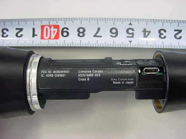
Click to zoom
Application Details
- Equipment Class
- DTS - Digital Transmission System
- Date of Grant
- Apr 25, 2010
- Application Purpose
- Original Equipment
- Date of Application
- Apr 25, 2010
- Equipment Note
- Digital Wireless Microphone
- Frequency Range
- 2405.00000000 - 2475.00000000
- Company
- Sony Group Corporation
- Country
- Japan
Documents & Files
Document Text
Text extracted from the exhibit documents filed with the FCC. Open a document above to read the original.
Users Manual
4-177-129-11 (1) © 2010 Sony Corporation Digital Wireless Microphone Operating Instructions Before operating the unit, please read this manual thoroughly and retain it for future reference. DWM-01 The supplied CD-ROM includes the Operating Instructions for the DWM-01 Digital Wireless Microphone (English, French, German, Italian, Spanish, and Japanese versions) and the frequency lists (English and Japanese versions) in PDF format. For more details, see “Using the CD-ROM Manual” on page 21. 2 WARNING Batteries shall not be exposed to excessive heat such as sunshine, fire or the like. For the customers in the U.S.A. This equipment has been tested and found to comply with the limits for a Class B digital device, pursuant to Part 15 of the FCC Rules. These limits are designed to provide reasonable protection against harmful interference in a residential installation. This equipment generates, uses, and can radiate radio frequency energy and, if not installed and used in accordance with the instructions, may cause harmful interference to radio communications. However, there is no guarantee that interference will not occur in a particular installation. If this equipment does cause harmful interference to radio or television reception, which can be determined by turning the equipment off and on, the user is encouraged to try to correct the interference by one or more of the following measures: - Reorient or relocate the receiving antenna. - Increase the separation between the equipment and receiver. - Connect the equipment into an outlet on a circuit different from that to which the receiver isconnected. - Consult the dealer or an experienced radio/TV technician for help. You are cautioned that any changes or modifications not expressly approved in this manual could void your authority to operate this equipment. All interface cables used to connect peripherals must be shielded in order to comply with the limits for a digital device pursuant to Subpart B of Part 15 of FCC Rules. If you have any questions about this product, you may call; Sony Customer Information Service Center 1-800-222-7669 or http://www.sony.com/ Notice for customers in the U.S.A. Use of Sony wireless devices is regulated by the Federal Communications Commision as described in Part 74 subpart H of the FCC regulations and users authorized thereby are required to obtain an appropriate license. IMPORTANT NOTE: To comply with the FCC RF exposure compliance requirements, no change to the antenna or the device is permitted, Any change to the antenna or the device could result in the device exceeding the RF exposure requirements and void user’s authority to operate this device. This device complies with FCC radiation exposure limits set forth for uncontrolled equipment and meets the FCC radio frequency (RF) Exposure Guidelines in Supplement C to OET65. This device has very low levels of RF energy that it is deemed to comply without testing of specific absorption radio (SAR). Declaration of Conformity Trade Name: SONY Model: DWM-01 Responsible Party: Sony Electronics Inc. Address: 16530 Via Esprillo, San Diego, CA 92127 U.S.A. Telephone Number: 858-942-2230 This device complies with part 15 of the FCC Rules. Operation is subject to the following two conditions: (1) this device may not cause harmful interference, and (2) this device must accept any interference received, including interference that may cause undesired operation. 3 For customers in Canada This Class B digital apparatus complies with Canadian ICES-003. For the customers in Canada Operation is subject to the following two conditions: (1) this device may not cause interference, and (2) this device must accept any interference, including interference that may cause undesired operation of the device. The term “IC” before the radio certification number only signifies that Industry Canada technical specifications were met. Notice for customers in Canada: Use of Sony wireless devices is regulated by the Industry Canada as described in their Radio Standard Specification RSS-123. A licence is normally required. The local district office of Industry Canada should therefore be contacted. When the operation of the device is within the broadcast band, the licence is issued on no-interference, noprotection basis with respect to broadcast signals. AVERTISSEMENT N’exposez pas les batteries à une chaleur excessive, au soleil ou près d’un feu par exemple. Pour les utilisateurs au Canada Cet appareil numérique de la classe B est conforme à la norme NMB-003 du Canada. L’utilisation doit répondre aux deux conditions suivantes : (1) ce matériel ne doit pas provoquer de brouillage et (2) il doit accepter tout brouillage, même celui qui est susceptible d’affecter son fonctionnement. La mention « IC: » devant le numéro de certification/ homologation signifie uniquement que les spécifications techniques d’Industrie Canada sont remplies. Remarque à l’intention des utilisateurs au Canada: L’usage des appareils sans fil Sony est réglementé par l’Industrie Canada comme décrit dans leur Cahier des Normes Radioélectriques CNR-123. Une licence est normalement requise. Le bureau de l’Industrie Canada doit être contacté. Lorsque le fonctionnement de l’appareil respecte les limites de la bande de radiodiffusion, la licence est accordée sur la base d’une non-interférence, non- protection pour les signaux de radiodiffusion. WARNUNG Akkus dürfen keinesfalls übermäßiger Wärmeeinwirkung ausgesetzt werden, wie z.B. Sonneneinstrahlung, Feuer o. ä. AV VE RT E N Z A Le batterie non devono essere esposte a fonti di calore eccessivo come luce solare diretta, fuoco, ecc. ADVERTENCIA No se deben exponer las baterÌas a una fuente de calor excesivo como la luz del sol, el fuego o similar. U.K.470 - 862 MHz Germany470 - 606 MHz, 614 - 862 MHz Norway800 - 820 MHz Luxembourg470 - 862 MHz Belgium470 - 862 MHz Denmark800.100 - 819.900 MHz France470 - 830 MHz Italy470 - 854 MHz Sweden470 - 862 MHz Switzerland790 - 862 MHz Finl…
Text truncated - open the document above for the full version.
External Photos
Outline Photo Document Model DWM-0 Fig.01 Top side View Fig.02 Bottom side View Outline Photo Document Model DWM-0 Fig.03 Front side View Fig.04 Rear side View Outline Photo Document Model DWM-0 Fig.05Display & switches Fig.06Label (ID) Outline Photo Document Model DWM-0 Fig.07 Label (Model name)
ID Label/Location Info
FCC/IC ID Marking Point Name Plate (DWM-01)
Internal Photos
Inner structure Photo Document Model DWM-01 Fig.1 Microphone, Cushion and Grip Fig.2 Microphone, Cushion and Grip Inner structure Photo Document Model DWM-01 Fig.03Grip Fig.04Main block & Grip Inner structure Photo Document Model DWM-01 Fig.05 Main block (Front side view) Fig.06 Disassembly of “AU-329 Mount” Inner structure Photo Document Model DWM-01 Fig.07 AU-329 Mount (Side-A) Fig.08 AU-329 Mount (Side-B) Inner structure Photo Document Model DWM-01 Fig.09 Disassembly of “Grip_D” Fig.10 Grip_D Inner structure Photo Document Model DWM-01 Fig.11 Disassembly of “Battery case assembly” Fig.12 Battery case assembly(Front side) Inner structure Photo Document Model DWM-01 Fig.13 Battery case assembly(Rear side) Fig.14 Disassembly of “Antenna”, “AN-36 Mount”, “RF-145 Mount” Inner structure Photo Document Model DWM-01 Fig.15 Antenna Fig.16 RF-145 mount (Side-B) Inner structure Photo Document Model DWM-01 Fig.17 RF-145 mount (Side-A) Fig.18 AN-36 Mount (Side-A) – Antenna for 2.4GHz RF Inner structure Photo Document Model DWM-01 Fig.19 AN-36 Mount (Side-B) Fig.20 Disassembly of “DPR-320 Mount” Inner structure Photo Document Model DWM-01 Fig.21 Chassis (Inside view) Fig.22 Chassis (Front view) Inner structure Photo Document Model DWM-01 Fig.23 DPR-320 Mount (Side-B) Fig.24 DPR-320 Mount (Side-A) Inner structure Photo Document Model DWM-01 Fig.25 Disassembly of “OEL Display holder Fig.26 RF-151 Mount (Side-A) Inner structure Photo Document Model DWM-01 Fig.27 RF-151 Mount (Side-B) Fig.28 2.4GHz RF Block (DPR-320) Inner structure Photo Document Model DWM-01 Fig.30 2.4GHz RF Block (DPR-320 A) Fig.31 2.4GHz RF Block (DPR-320 B) Inner structure Photo Document Model DWM-01 Fig. 33 Antenna for 2.4GHz to Antenna for Wireless Microphone (Main Part): 7mm Fig. 32 Position of Antenna for 2.4GHz and Antenna for Wireless Microphone Inner structure Photo Document Model DWM-01 Fig. 34 Antenna for 2.4GHz to Antenna for Wireless Microphone (Feeding Point): 3mm
Test Report
Page 1 of 64 Technical document No. 23160-0701 JQA File No. : 400-090422 Issue Date : March 26, 2010 TEST REPORT APPLICANT : Sony Corporation ADDRESS : 1-7-1 Konan, Minato-ku, Tokyo, 108-0075, Japan PRODUCTS : Digital Wireless Microphone(2.4GHz TX/RX portion) MODEL No. : DWM-01 SERIAL No. : -- (Sample No.) : (1021) FCC ID : AK8DWM01 IC : 409B-DWM01 TEST STANDARD : CFR 47 FCC Rules and Regulations Part 15 Subpart A, B and C : Industry Canada RSS-210(Issue 7) and RSS-Gen(Issue 2) TESTING LOCATION : Japan Quality Assurance Organization SAFETY & EMC CENTER EMC Engineering Department Testing Division 1-21-25, Kinuta, Setagaya-ku, Tokyo 157-8573, Japan TEST RESULTS : Passed DATE OF TEST : March 1, 2010 - March 19, 2010 This report must not used by the client to claim product endorsement by NVLAP or NIST or any agency of the U.S. Government. Eiichi Saegusa Manager Japan Quality Assurance Organization SAFETY & EMC CENTER EMC Engineering Dept. Testing Division NVLAP LAB CODE 200189 -0 1-21-25, Kinuta, Setagaya-ku, Tokyo 157-8573, Japan ● The measurement values stated in Test Report was made with traceable to National Institute of Advanced Industrial Science and Technology (AIST) of Japan and National Institute of Information and Communications Technology (NICT) of Japan. ● The applicable standard, testing condition and testing method which were used for the tests are based on the request of the applicant. ● The test results presented in this report relate only to the offered test sample. ● The contents of this test report cannot be used for the purposes, such as advertisement for consumers. ● This test report shall not be reproduced except in full without the written approval of JQA. JQA File No. : 400-090422 Issue Date : March 26, 2010 Model No. : DWM-01 FCC ID : AK8DWM01 IC : 409B-DWM01 Standard : FCC Part 15 / RSS-210(Issue 7) and RSS-Gen(Issue 2) Page 2 of 64 Technical document No. 23160-0701 Table of Contents Documentation Page 1 Test Regulation 3 2 Test Location 3 3 Recognition of Test Laboratory 3 4 Description of the Equipment Under Test 4 5 Test Condition 5-12 6 Preliminary Test and Test Setup 13-21 7 Equipment Under Test Modification 22 8 Responsible Party 22 9 Deviation from Standard 22 10 Test Results 23-29 11 Summary 30 12 Operating Condition 31 13 Test Configuration 32 14 Equipment Under Test Arrangement (Drawings) 33 Appendix A : Test Data 34-57 A.1 Channel Separation A.2 Minimum Hopping Channel A.3 Occupied Bandwidth A.4 Dwell Time A.5 Peak Output Power (Conduction) A.6 Peak Output Power (Radiation) A.7 Peak Power Density (Conduction) A.8 Peak Power Density (Radiation) A.9 Spurious Emissions (Conduction) A.10 Spurious Emissions for Transmitter (Radiation) A.11 AC Power Line Conducted Emissions for Transmitter A.12 RF Exposure Compliance A.13 Spurious Emissions for Receiver (Radiation) A.14 AC Power Line Conducted Emissions for Receiver Appendix B : Test Arrangement (Photographs) 58-61 Appendix C : Test Instruments 62-64 Definitions for Abbreviation and Symbols Used In This Test Report “EUT” means Equipment Under the Test. “AE” means Associated Equipment. “N/A” means that Not Applicable. “N/T” means that Not Tested. -indicates that the listed condition, standard or equipment is applicable for this report. -indicates that the listed condition, standard or equipment is not applicable for this report. JQA File No. : 400-090422 Issue Date : March 26, 2010 Model No. : DWM-01 FCC ID : AK8DWM01 IC : 409B-DWM01 Standard : FCC Part 15 / RSS-210(Issue 7) and RSS-Gen(Issue 2) Page 3 of 64 Technical document No. 23160-0701 Documentation 1 Test Regulation Applied Standard : CFR 47 FCC Rules and Regulations Part 15 Subpart A, B and C Industry Canada RSS-210(Issue 7) and RSS-Gen(Issue 2) Test Procedure : The tests were performed with reference to the FCC Public Notice DA 00-705, released March 30, 2000. The test set-up was made in accordance to the general provisions of ANSI C63.4-2003. 2 Test Location Japan Quality Assurance Organization SAFETY & EMC CENTER EMC Engineering Department Testing Division 1-21-25, Kinuta, Setagaya-ku, Tokyo 157-8573, Japan 3 Recognition of Test Laboratory Japan Quality Assurance Organization SAFETY & EMC CENTER EMC Engineering Department Testing Division is accredited under ISO/IEC 17025 by following accreditation bodies and the test facility of Testing Division is registered by the following bodies . VLAC Code : VLAC-001-1 (Effective through : April 3, 2010) NVLAP Lab Code : 200189-0 (Effective through : June 30, 2010) VCCI Registration Number : R-002, R-003, C-002, C-966 (Effective through : April 3, 2010) FCC Registration Number : 349652 (Date of Listing : April 1, 2010) IC Registration Number : 2079-7, 2079-8 (Effective through : August 29, 2011) Accredited as conformity assessment body for Japan electrical appliances and material law by METI. (Effective through : February 22, 2013) JQA File No. : 400-090422 Issue Date : March 26, 2010 Model No. : DWM-01 FCC ID : AK8DWM01 IC : 409B-DWM01 Standard : FCC Part 15 / RSS-210(Issue 7) and RSS-Gen(Issue 2) Page 4 of 64 Technical document No. 23160-0701 4 Description of the Equipment Under Test 1 Manufacturer : Sony EMCS Corporation Kosai Tec. 554 Sakaijuku Kosai-shi, Shizuoka-ken, 431-0496, Japan 2 Products : Digital Wireless Microphone(2.4GHz TX/RX portion) 3 Trade Name : SONY 4 Model No. : DWM-01 5 Serial No. (Sample No.) : None (1021) 6 FCC ID : AK8DWM01 7 IC : 409B-DWM01 8 Product Type : Prototype 9 Date of Manufacture : -- 10 Power Rating : 3.0 VDC(Battery) 11 EUT Grounding : None 12 Category : Transceiver(DSSS type) 13 Received Date of EUT : February 22, 2010 14 EUT Authorization : Certification 15 Fundamental Frequency Generated/used in the EUT : 1.3 MHz, 1.5 MHz, 8 MHz and 16 MHz 16 Operating Frequency Range : 2405 MHz - 2475 MHz 17 EUT Highest Frequency Used/Generated : 2475 MHz 18 RF Output Power : -0.34 dBm(measured value) 19 Antenna Type : Ceramic Patch Antenna (Integral Internal antenna : not accessible to …
Text truncated - open the document above for the full version.
Test Setup Photos
JQA File No. : 400-090422 Issue Date : March 26, 2010 Model No. : DWM-01 FCC ID : AK8DWM01 IC : 409B-DWM01 Standard : FCC Part 15 / RSS-210(Issue 7) and RSS-Gen(Issue 2) Page 58 of 64 Technical document No. 23160-0701 Appendix B : Test Arrangement (Photographs) B.1.1 External B.1.2 Conducted Test JQA File No. : 400-090422 Issue Date : March 26, 2010 Model No. : DWM-01 FCC ID : AK8DWM01 IC : 409B-DWM01 Standard : FCC Part 15 / RSS-210(Issue 7) and RSS-Gen(Issue 2) Page 59 of 64 Technical document No. 23160-0701 B.1.3 Radiated Emissions - X-axis - - Y-axis - Photograph present configuration with maximum emission JQA File No. : 400-090422 Issue Date : March 26, 2010 Model No. : DWM-01 FCC ID : AK8DWM01 IC : 409B-DWM01 Standard : FCC Part 15 / RSS-210(Issue 7) and RSS-Gen(Issue 2) Page 60 of 64 Technical document No. 23160-0701 - Z-axis - Photograph present configuration with maximum emission JQA File No. : 400-090422 Issue Date : March 26, 2010 Model No. : DWM-01 FCC ID : AK8DWM01 IC : 409B-DWM01 Standard : FCC Part 15 / RSS-210(Issue 7) and RSS-Gen(Issue 2) Page 61 of 64 Technical document No. 23160-0701 B.1.4 AC Power Line Conducted Emissions Not Applicable
Contact Information
Applicant
Kazuyuki Hori(Chief EMC/RF Compliance Specialist)
Test Firm
Japan Qlty. Assur. Org. Chubu Testing CenterYasuhisa Sakai
Technical Specifications
| # | Rule Parts | Frequency Range | Power Output |
|---|---|---|---|
| 1 | 15C | 2.40 GHz - 2.48 GHz | 900.00 µW |
Other Applications from Sony Group Corporation
AK8WW81782
Aug 21, 2026Radio Equipment
Equipment Class
DSS - Part 15 Spread Spectrum TransmitterAK8CFIZCP2
Aug 03, 2026Wireless Controller
Equipment Class
DSS - Part 15 Spread Spectrum TransmitterAK8OEV321MUH
Apr 14, 2026LCD Monitor
Equipment Class
JAD - Part 15 Class A Digital DeviceAK8OEV431MUH
Apr 14, 2026LCD Monitor
Equipment Class
JAD - Part 15 Class A Digital DeviceAK8OEV271MUH
Apr 14, 2026LCD Monitor
Equipment Class
JAD - Part 15 Class A Digital Device