AK8DWTB01NDigital Wireless Transmitter
Sony Group Corporation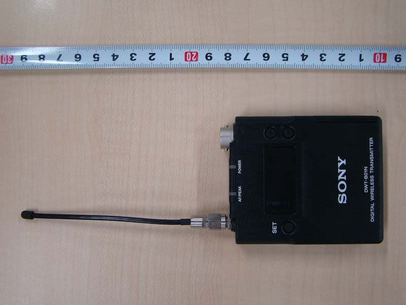
Click to zoom
Application Details
- Equipment Class
- TBT - Licensed Broadcast Transmitter Worn on Body
- Date of Grant
- Oct 07, 2015
- Application Purpose
- Original Equipment
- Date of Application
- Oct 07, 2015
- Equipment Note
- Digital Wireless Transmitter
- Frequency Range
- 614.12500000 - 697.87500000
- Company
- Sony Group Corporation
- Country
- Japan
Documents & Files
Document Text
Text extracted from the exhibit documents filed with the FCC. Open a document above to read the original.
Users Manual
Digital Wireless Transmitter Operating Instructions DWT-B01N 4-585-173-01 (1) © 2015 Sony Corporation 2 Table of Contents Features ...................................................................... 3 Parts Identification ................................................... 4 Power Supply ............................................................. 5 Installing the batteries ............................................ 5 Setting the Transmission Channel ........................... 6 Selecting the group/channel ................................... 6 Using the Cross Remote ............................................ 7 Pairing with a receiver ........................................... 7 Using the Encrypted Transmission Function ......... 8 Using secure key mode (SECURE KEY) .............. 8 Using password mode (PASSWORD) .................. 8 Using a USB Keyboard ............................................. 9 Basic Menu Operations .......................................... 10 Setting Menus .......................................................... 10 Naming of transmitter (NAME) .......................... 10 Selecting the frequency band (BAND) ................ 10 Selecting the group/channel (GP/CH) ................. 11 Setting the RF output power (RF POWER) ........ 11 Setting the audio input level (INPUT LEVEL) ... 11 Low-cut filter setting (LCF) ................................ 11 Power save setting (POWER SAVE) .................. 11 Setting the battery type (BATTERY TYPE) ....... 12 Displaying the accumulated use time (TIME) ..... 12 Setting the encrypted transmission function (ENCRYPTION) ............................................... 12 Setting the audio codec mode (CODEC MODE) .............................................................. 12 Setting the maximum RF output power (MAX RF POWER) ............................................................ 12 Generating an internal signal (INTERNAL SG) ............................................... 12 Locking the POWER switch (POWER SW LOCK) ........................................................ 13 Cross Remote (RF REMOTE) ............................. 13 Setting the brightness of the display (BRIGHTNESS) ................................................ 13 Automatic dimming of the display (DIMMER MODE) .............................................................. 13 Resetting parameters to their factory settings (FACTORY PRESET) ...................................... 13 Displaying the software version (VERSION) ..... 13 Attaching With the Soft Case ................................. 14 Removing the clip ................................................ 14 Attaching the Antenna Tubes ................................. 14 Attaching the antenna tubes ................................. 14 Removing the antenna tubes ................................ 14 Block Diagram ......................................................... 15 Troubleshooting ....................................................... 16 Important Notes on Operation .............................. 17 Notes on using the transmitter ............................. 17 On cleaning .......................................................... 17 Specifications ........................................................... 18 Carrier Frequencies and Channel Steps ............... 19 3 Features The DWT-B01N is a digital wireless transmitter for a UHF synthesized wireless microphone system to be used for broadcast or movie production purpose. This transmitter is suitable for Electronic News Gathering (ENG) and Electronic Field Production (EFP). What is DWX? DWX refers to Sony’s new digital wireless microphone system. The DWX series reflects Sony’s extensive expertise in professional microphones and sound design. It represents a successful blend of Sony know-how, wireless technology renowned for stability, and cutting-edge digital audio technology. In addition to realizing the high sound quality possible with a digital system, the DWX series supports multi- channel simultaneous operation, encrypted transmission, and metadata transmission for monitoring the status of multiple transmitters. Using a main link and a separate additional link, remote control of transmitters from the receiver is also possible. With its many advanced features, the system has the potential to revolutionize the workflow of professional applications. What is WiDIF-HP? WiDIF-HP (WiDIF: Wireless Digital Interface Format, HP: High Profile) is a wireless digital audio interface format developed by Sony. It enables highly secure transmission with high sound quality and low system latency, and supports simultaneous multi-channel operation. What is Cross Remote? Cross Remote is a system that allows transmitters to be monitored and controlled from a receiver and the Wireless Studio control software installed on a computer connected to the receiver. For example, the settings of a transmitter worn under clothing can be easily changed over the wireless link. Wide RF carrier frequency range The DWT-B01N transmitter covers an extremely wide RF carrier frequency range. Depending on the model, the transmitter can cover bandwidths between 48-MHz and 72-MHz (e.g., 72-MHz with the CE4248 1) ) — much wider than 24-MHz of the analog wireless microphone system. This remarkably wide coverage on a single model offers cost efficiency and operational convenience, because it allows one transmitter to be operated in many different areas. 1) Carrier frequencies differ depending on the model. Compact, lightweight, and rugged design The DWT-B01N is designed to be extremely compact and lightweight, essential qualities for use by artists in fast- moving TV and outdoor productions. Switchable mic or line input level and adjustable attenuator For details, see “Setting the audio input level (INPUT LEVEL)” on page 11. Three audio codec modes Switch between audio codec modes based on your operational needs. For details, see “Setting the audio codec mode (CODEC …
Text truncated - open the document above for the full version.
Cover Letter(s)
Sony EMCS Corporation 30 Ibarajima Ohya-cho Inazawa-shi, Aichi 492-8545 Japan Date: August 4, 2015 UL Verification Services Inc. 47173 Benicia Street, Fremont, CA 94538 Reference: Applicant: Sony Corporation FCC ID: AK8DWTB01N To whom it may concern: We, the undersigned, hereby authorize Yoshihisa Maeda of Consumer Technology Division, UL Japan, Inc. to act on our behalf in all manners relating to application for equipment authorization, including signing of all documents relating to these matters. Any and all acts carried out by UL Japan, Inc. on our behalf shall have the same effect as acts of our own. We, the undersigned, hereby certify that we are not subject to a denial of federal benefits, that includes FCC benefits, pursuant to Section 5301 of the Anti-Drug Abuse Act of 1988, 21 U.S.C. 862. This authorization is valid until further written notice from the applicant. The application for the subject equipment has not been submitted to another TCB for certification. Sincerely Yours, Hideo Nomura Senior Manager Product Safety Section, Quality Assurance Department 3, Sony EMCS Corporation
Cover Letter(s)
Sony EMCS Corporation 30 Ibarajima Ohya-cho Inazawa-shi, Aichi 492-8545 Japan Request for Confidentiality Date: August 21, 2015 UL Verification Services Inc. 47173 Benicia Street, Fremont, CA 94538 FCC ID : AK8DWTB01N Applicant : Sony Corporation To whom it may concern: Please be advised that the following information is to be held confidential on behalf of us, referring to the FCC rules 0.457 and 0.459: Block Diagram Theory of Operation Schematics Parts List The application contains technical information which we deem to be trade secrets and proprietary. If made public, the information might be used to the disadvantage of the applicant in the market place. Thank you for your attention to this matter. Sincerely, Hideo Nomura Senior Manager Product Safety Section, Quality Assurance Department 3, Sony EMCS Corporation
Cover Letter(s)
Sony EMCS Corporation 30 Ibarajima Ohya-cho Inazawa-shi, Aichi 492-8545 Japan Request for Short-Term Confidentiality Date: August 21, 2015 UL Verification Services Inc. 47173 Benicia Street, Fremont, CA 94538 FCC ID : AK8DWTB01N Applicant : Sony Corporation To whom it may concern: Please be advised that the following information is to be held in confidence for 180 days from the date of the Grant of Equipment Authorization and behalf of us, referring to the FCC rules 0.457 and 0.459: External Photos Internal Photos Test Setup Photos User Manual The application contains technical information, which we deem to be trade secrets and proprietary. If made public, the information might be used to the disadvantage of the applicant in the market place. Thank you for your attention to this matter. Sincerely, ____________________________________ Hideo Nomura Senior Manager Product Safety Section, Quality Assurance Department 3, Sony EMCS Corporation
External Photos
Outline photograph document: Model DWT-B01N Fig.1: Front side view Fig.2: Rear side view Outline photograph document: Model DWT-B01N Fig.3: Top side view Fig.4: Bottom side view Outline photograph document: Model DWT-B01N Fig.5: Right side view Fig.6: Left side view
ID Label/Location Info
DWT-B01N Outline drawing Model Number Label DWT-B01 Model Number Label Label (U14) Label (U30) Label (U42)
Internal Photos
Inner structure document: Model DWT-B01N Fig.1: Removed the rear panel Fig.2: Removed the board AU-354 Inner structure document: Model DWT-B01N Fig.3: Side A of board AU-354 Fig.4: Side B of board AU-354 Inner structure document: Model DWT-B01N Fig.5: Removed the board TX-147 Fig.6: Side A of board TX-147 Inner structure document: Model DWT-B01N Fig.7: Side B of board TX-147 Fig.8: Removed the board DPR-356 Inner structure document: Model DWT-B01N Fig.9: Side A of board DPR-356 Fig.10: Side B of board DPR-356 Inner structure document: Model DWT-B01N Fig.11: Removed the MIC connector and RM assembly Fig.12: MIC connector Inner structure document: Model DWT-B01N Fig.13: RM assembly Fig.14: Side A of board RM-215 Inner structure document: Model DWT-B01N Fig.15: Side B of board RM-215 Fig.16: Side A of board LED-498 Inner structure document: Model DWT-B01N Fig.17: Side B of board LED-498 Fig.18: Removed the antenna connector
Test Report
Test report No. : 10686937H-B-R1 Page : 2 of 32 Issued date : March 16, 2015 Revised date : September 30, 2015 FCC ID : AK8DWTB01N UL Japan, Inc. Ise EMC Lab. 4383-326 Asama-cho, Ise-shi, Mie-ken 516-0021 JAPAN Telephone : +81 596 24 8999 Facsimile : +81 596 24 8124 REVISION HISTORY Original Test Report No.: 10686937H-B Revision Test report No. Date Page revised Contents - (Original) 10686937H-B March 16, 2015 - - 1 10686937H-B-R1 September 30, 2015 P.4 Correction of clock frequency of IC600, 601, 700, 720, 721 1 10686937H-B-R1 September 30, 2015 P.5 Correction of channel spacing of Radio microphone part 1 10686937H-B-R1 September 30, 2015 P.9 Addition of explanatory for operating mode Test report No. : 10686937H-B-R1 Page : 3 of 32 Issued date : March 16, 2015 Revised date : September 30, 2015 FCC ID : AK8DWTB01N UL Japan, Inc. Ise EMC Lab. 4383-326 Asama-cho, Ise-shi, Mie-ken 516-0021 JAPAN Telephone : +81 596 24 8999 Facsimile : +81 596 24 8124 CONTENTS PAGE SECTION 1: Customer information ......................................................................................................... 4 SECTION 2: Equipment under test (E.U.T.) ........................................................................................... 4 SECTION 3: Test specification, procedures & results ............................................................................ 6 SECTION 4: Operation of E.U.T. during testing .................................................................................... 9 SECTION 5: Field strength of spurious radiation ................................................................................ 11 SECTION 6: Antenna terminal tests, Emission Bandwidth and Frequency stability ....................... 12 APPENDIX 1: Data of Radio test ........................................................................................................... 13 RF power output ......................................................................................................................... 13 Emission Bandwidth ................................................................................................................... 14 Spurious emissions at antenna terminals ................................................................................. 17 Field strength of spurious radiation .......................................................................................... 26 Frequency stability ..................................................................................................................... 29 APPENDIX 2: Test instruments ............................................................................................................. 30 APPENDIX 3: Photographs of test setup ............................................................................................... 31 Radiated Spurious Emission ...................................................................................................... 31 Worst Case Position (Horizontal: X-axis/ Vertical:Y-axis) .................................................... 32 Test report No. : 10686937H-B-R1 Page : 4 of 32 Issued date : March 16, 2015 Revised date : September 30, 2015 FCC ID : AK8DWTB01N UL Japan, Inc. Ise EMC Lab. 4383-326 Asama-cho, Ise-shi, Mie-ken 516-0021 JAPAN Telephone : +81 596 24 8999 Facsimile : +81 596 24 8124 SECTION 1: Customer information Company Name : Sony EMCS Corporation Address : 30 Ibarajima Ohya-cyo, Inazawa-shi, Aichi-ken, 492-8545, JAPAN Telephone Number : +81-50-3807-4243 Facsimile Number : +81-50-3807-4306 Contact Person : Youhei Hisano *Remarks Sony EMCS Corporation (Subsidiary Company Name) is on behalf of the applicant: Sony Corporation. SECTION 2: Equipment under test (E.U.T.) 2.1 Identification of E.U.T. Type of Equipment : Digital Wireless Transmitter Model No. : DWT-B01N Serial No. : Refer to 4.2 in this report. Rating : DC 3.0V (2 x AA batteries) Receipt Date of Sample : February 11, 2015 Country of Mass-production : Japan Condition of EUT : Engineering prototype (Not for Sale: This sample is equivalent to mass-produced items.) Modification of EUT : No Modification by the test lab 2.2 Product Description Model: DWT-B01N (referred to as the EUT in this report) is a Digital Wireless Transmitter. General Specification Clock frequency(ies) in the system : X400 8MHz X202 12.288MHz X2000 16MHz X801 (TCXO) 19.2MHz IC600, 601, 700, 720, 721 1250 - 1500kHz IC702 1300kHz IC202 600 - 1000kHz IC606 250kHz X802 (VCO: change by a transmission frequency) (14) 470.125-541.875MHz (30) 566.125-607.875MHz, 614.125-637.875MHz (42) 638.125-697.875MHz Test report No. : 10686937H-B-R1 Page : 5 of 32 Issued date : March 16, 2015 Revised date : September 30, 2015 FCC ID : AK8DWTB01N UL Japan, Inc. Ise EMC Lab. 4383-326 Asama-cho, Ise-shi, Mie-ken 516-0021 JAPAN Telephone : +81 596 24 8999 Facsimile : +81 596 24 8124 Radio Specification (Radio microphone part) Radio type : Transmitter Modulation type : π/4 shift QPSK Emission designator : 192KG1D, 192KG1E Necessary bandwidth : 192kHz, Manufacturer defined Channel spacing : 25kHz Frequency of operation : (14) 470.125-541.875MHz (30) 566.125-607.875MHz, 614.125-637.875MHz (42) 638.125-697.875MHz RF power : High: 50mW, Middle: 10mW, Low: 1mW Antenna type : 1/4 Lambda Monopole antenna (whip type) Antenna gain : 2.14dBi Power Supply (radio part input) : DC 2.8V, DC 3.0V, DC 5.0V AF Specification : 40Hz – 18000Hz, Maximum input: -24dBV (MIC level, ATT 0dB) Operating temperature : 0 deg. C to 50 deg. C Radio Specification (RF remote part) Radio Type : Transceiver Modulation type : DSSS Frequency of Operation : 2405MHz to 2480MHz Channel spacing : 5MHz Method of frequency generation : Synthesizer Power Supply (radio part input) : DC 2.8V Antenna Type : Chip antenna Antenna Gain : -1.0dBi max Operating temperature : 0 deg. C to 50 deg. C *This test report applies for Radio microphone part. Test report No. : 10686937H-B-R1 Page : 6 of 32 Issued date : March 16…
Text truncated - open the document above for the full version.
Test Setup Photos
Test report No. : 10686937H-B-R1 Page : 31 of 32 Issued date : March 16, 2015 Revised date : September 30, 2015 FCC ID : AK8DWTB01N UL Japan, Inc. Ise EMC Lab. 4383-326 Asama-cho, Ise-shi, Mie-ken 516-0021 JAPAN Telephone : +81 596 24 8999 Facsimile : +81 596 24 8124 APPENDIX 3: Photographs of test setup Radiated Spurious Emission Photo 1 Photo 2 Test report No. : 10686937H-B-R1 Page : 32 of 32 Issued date : March 16, 2015 Revised date : September 30, 2015 FCC ID : AK8DWTB01N UL Japan, Inc. Ise EMC Lab. 4383-326 Asama-cho, Ise-shi, Mie-ken 516-0021 JAPAN Telephone : +81 596 24 8999 Facsimile : +81 596 24 8124 Worst Case Position (Horizontal: X-axis/ Vertical:Y-axis) X-axis Y-axis Z-axis End of Report
Contact Information
Applicant
Kazuyuki Hori(Chief EMC/RF Compliance Specialist)
Technical Contact
UL Japan, Inc.Takayuki Shimada
[email protected]81-596-24-8999
4383-326 Asama-cho, Ise-shi · Mie-ken · Japan
Test Firm
UL Japan, Inc. Head office EMC Lab.Tetsuya Hashimoto
Technical Specifications
| # | Rule Parts | Frequency Range | Power Output | Emission | Tolerance |
|---|---|---|---|---|---|
| 4 | 74.861 | 614.125 MHz - 697.875 MHz | 50.00 mW | 192KG1E | 6.5 ppm |
Other Applications from Sony Group Corporation
AK8WW81782
Aug 21, 2026Radio Equipment
Equipment Class
DSS - Part 15 Spread Spectrum TransmitterAK8CFIZCP2
Aug 03, 2026Wireless Controller
Equipment Class
DSS - Part 15 Spread Spectrum TransmitterAK8OEV321MUH
Apr 14, 2026LCD Monitor
Equipment Class
JAD - Part 15 Class A Digital DeviceAK8OEV431MUH
Apr 14, 2026LCD Monitor
Equipment Class
JAD - Part 15 Class A Digital DeviceAK8OEV271MUH
Apr 14, 2026LCD Monitor
Equipment Class
JAD - Part 15 Class A Digital Device