AK8DWTP30DIGITAL WIRELESS TRANSMITTER
Sony Group Corporation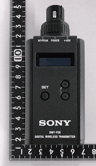
Click to zoom
Application Details
- Equipment Class
- DWM - Part 15 Wireless Microphone
- Date of Grant
- Nov 20, 2022
- Application Purpose
- Original Equipment
- Date of Application
- Nov 20, 2022
- Equipment Note
- DIGITAL WIRELESS TRANSMITTER
- Frequency Range
- 614.12500000 - 615.87500000
- Company
- Sony Group Corporation
- Country
- Japan
Documents & Files
Document Text
Text extracted from the exhibit documents filed with the FCC. Open a document above to read the original.
Users Manual
DWT-P30 flyer (GB) 5-047-398-01 (1) English L-2_v009-000_5-047-398-01(1)_202209221137_GB_1/96 Before operating the unit, please read this manual thoroughly and retain it for future reference. L-1_v004-000_5-047-398-01(1)_202209221137_GB_2/96 CAUTION • Danger of explosion if battery is incorrectly replaced. Replace only with the same or equivalent type recommended by the manufacturer. •Use the battery which complied with IEC 60086-5 standard (Alkaline batteries), IEC 60086-4 standard (Lithium batteries) or IEC 62133-1 standard (Rechargeable nickel-metal-hydride batteries). • When you dispose of the battery or the product, you must obey the law in the corresponding area or country. Do not dispose of the battery or the product in a fire or a hot oven, or mechanically crush or cut the battery. It may explode or cause a fire. Do not subject the battery to extremely low air pressure that may result in an explosion or the leakage of flammable liquid or gas. • Do not place the battery in a high temperature place, such as under direct sunlight or near fire. It may ignite, explode, or cause a fire. Do not immerse or wet the battery in water or seawater. This may cause an electric shock. S-4F_v002-000_5-047-398-01(1)_202209221137_GB_3/96 ATTENTION The electromagnetic fields at the specific frequencies may influence the sound of this unit. E-24B_v012-000_5-047-398-01(1)_202209221137_GB_4/96 All interface cables used to connect the equipment to peripherals must be shielded type to comply with EMC standard(s) and to prevent undesired operation due to radiated emissions. When cables are supplied, always use them for this purpose. E-8_v014-000_5-047-398-01(1)_202209221137_GB_5/96 For the customers in the U.S.A. This equipment has been tested and found to comply with the limits for a Class B digital device, pursuant to part 15 of the FCC Rules. These limits are designed to provide reasonable protection against harmful interference in a residential installation. This equipment generates, uses and can radiate radio frequency energy and, if not installed and used in accordance with the instructions, may cause harmful interference to radio communications. However, there is no guarantee that interference will not occur in a particular installation. If this equipment does cause harmful interference to radio or television reception, which can be determined by turning the equipment off and on, the user is encouraged to try to correct the interference by one or more of the following measures: • Reorient or relocate the receiving antenna. • Increase the separation between the equipment and receiver. • Connect the equipment into an outlet on a circuit different from that to which the receiver is connected. • Consult the dealer or an experienced radio/TV technician for help. E-6_v003-000_5-047-398-01(1)_202209221137_GB_6/96 Changes or modifications not expressly approved by the party responsible for compliance could void the user’s authority to operate the equipment. E-7A_v003-000_5-047-398-01(1)_202209221137_GB_7/96 If you have any questions about this product, you may call: Sony Customer Information Service Center 1-800-222-7669 or http:// www.sony.com/ Supplier’s Declaration of Conformity Trade Name: SONY Model: DWT-P30 Responsible party: Sony Electronics Inc. Address: 16535 Via Esprillo, San Diego, CA 92127 U.S.A. Telephone Number: 858-942-2230 This device complies with part 15 of the FCC Rules. Operation is subject to the following two conditions: (1) This device may not cause harmful interference, and (2) this device must accept any interference received, including interference that may cause undesired operation. E-10A_v004-000_5-047-398-01(1)_202209221137_GB_8/96 You are cautioned that any changes or modifications not expressly approved in this manual could void your authority to operate this equipment. R-3_v002-000_5-047-398-01(1)_202209221137_GB_9/96 All interface cables used to connect peripherals must be shielded in order to comply with the limits for a digital device pursuant to Subpart B of part 15 of FCC Rules. R-4_v003-000_5-047-398-01(1)_202209221137_GB_10/96 FCC Radiation Exposure Statement The available scientific evidence does not show that any health problems are associated with using low power wireless devices. There is no proof, however, that these low power wireless devices are absolutely safe. Low power Wireless devices emit low levels of radio frequency energy (RF) in the microwave range while being used. Whereas high levels of RF can produce health effects (by heating tissue), exposure of low-level RF that does not produce heating effects causes no known adverse health effects. Many studies of low-level RF exposures have not found any biological effects. Some studies have suggested that some biological effects might occur, but such findings have not been confirmed by additional research. DWT-P30 has been tested and found to comply with FCC radiation exposure limits set forth for an uncontrolled environment and meets the FCC radio frequency (RF) Exposure Guidelines. R-7_v004-000_5-047-398-01(1)_202209221137_GB_12/96 This transmitter must not be co-located or operated in conjunction with any other antenna or transmitter. W-11_v002-000_5-047-398-01(1)_202209221137_GB_13/96 Antenna type: λ/4 Monopole integral antenna Users need to register with and check a white-space database to determine available channels prior to operation at a given location. W-15_v002-000_5-047-398-01(1)_202209221137_GB_14/96 This model contains an FCC-approved RF module. RF Module : RM-215 Contains FCC ID: AK8RM215 W-4B_v002-000_5-047-398-01(1)_202209221137_GB_15/96 In order to comply with FCC radio-frequency radiation exposure guidelines for an uncontrolled exposure, this device and its antenna must not be co-located or operating in conjunction with any other antenna or transmitter. R-78_v002-000_5-047-398-01(1)_202209221137_GB_16/96 For the customers in Canada CAN ICES-3 (B)/NMB-3(B) E-13_v002-000_5-047-398-01(1)_20220…
Text truncated - open the document above for the full version.
Users Manual
Digital Wireless Transmitter Operating Instructions DWT-P30 5-047-397-11 (1) © 2022 Sony Corporation 2 Table of Contents Features ...................................................................... 3 Parts Identification ................................................... 4 Power Supply ............................................................. 6 Installing the batteries ............................................ 6 Setting the Transmission Channel ........................... 7 Selecting the group/channel ................................... 7 Using Cross Remote .................................................. 8 Pairing with a receiver ........................................... 8 Using the Encrypted Transmission Function ......... 9 Using the encryption key modes (SECURE KEY / AES256) .............................................................. 9 Using the password mode (PASSWORD) ............ 9 Basic Menu Operations .......................................... 10 Setting Menus .......................................................... 10 Unit name setting (NAME) ................................. 10 Selecting the frequency band (BAND) ................ 10 Selecting the group/channel (GP/CH) ................. 11 Audio attenuator setting (AF ATT) ..................... 11 Low-cut filter setting (LCF) ................................ 11 Lock function (LOCK) ........................................ 11 Power save setting (POWER SAVE) .................. 11 Setting the battery type (BATTERY TYPE) ....... 12 Cross Remote (RF REMOTE) ............................. 12 Receiver search function (SEARCH RX) ............ 12 Audio codec mode setting (CODEC MODE) ..... 12 Encrypted transmission function Setting (ENCRYPTION) ............................................... 12 Audio input level setting (INPUT LEVEL) ......... 12 +48 V power supply setting (+48V) .................... 13 Audio phase switch function (AF PHASE) ......... 13 Generating an internal signal (INTERNAL SG) ..................................................................... 13 Setting the RF output power (RF POWER) ........ 13 Setting the maximum RF output power (MAX RF POWER) ............................................................ 13 Displaying the accumulated use time (TIME) ..... 13 Setting the brightness of the display (BRIGHTNESS) ................................................ 14 Automatic dimming of the display (DIMMER MODE) .............................................................. 14 Settings storage function (USER MEMORY) ..... 14 Power source priority setting (POWER PRIORITY) ........................................................ 14 Resetting parameters to their factory settings (FACTORY PRESET) ...................................... 14 Displaying the software version (VERSION) ..... 15 Block Diagram ......................................................... 16 Troubleshooting ....................................................... 17 Important Notes on Operation .............................. 18 Notes on using the transmitter ............................. 18 On cleaning .......................................................... 18 Notes on simultaneous multi-channel operation ............................................................ 18 Note on microphone and transmitter combinations ...................................................... 18 CROSS REMOTE Compatibility ........................ 18 Specifications ........................................................... 19 Carrier Frequencies and Channel Steps ............... 20 END USER LICENSE AGREEMENT (EULA) .. 21 3 Features The DWT-P30 is a digital wireless transmitter for a UHF synthesized wireless microphone system to be used for broadcast or movie production purpose. This transmitter is suitable for Electronic News Gathering (ENG), Electronic Field Production (EFP), and Location Sound. What is DWX? DWX refers to Sony’s new digital wireless microphone system. The DWX series reflects Sony’s extensive expertise in professional microphones and sound design. It represents a successful blend of Sony know-how, wireless technology renowned for stability, and cutting-edge digital audio technology. In addition to realizing the high sound quality possible with a digital system, the DWX series supports multi- channel simultaneous operation, encrypted transmission, and metadata transmission for monitoring the status of multiple transmitters. Using a main link and a separate additional link, remote control of transmitters from the receiver is also possible. With its many advanced features, the system has the potential to revolutionize the workflow of professional applications. What is WiDIF-HP? WiDIF-HP (WiDIF: Wireless Digital Interface Format, HP: High Profile) is a wireless digital audio interface format developed by Sony. It enables highly secure transmission with high sound quality and low system latency, and supports simultaneous multi-channel operation. What is Cross Remote? Cross Remote is a system that allows transmitters to be monitored and controlled from a receiver and the Wireless Studio control software installed on a computer connected to the receiver. For example, the settings of a transmitter worn under clothing can be easily changed over the wireless link. Simultaneous multi-channel operation Simultaneous multi-channel operation is made possible with the 375-kHz interval channel plan. High sound quality and low latency Low system latency of 1.2 ms (minimum) is achieved when using CODEC MODE2. Switch between four audio codec modes based on your operational needs. For details, see “Audio codec mode setting (CODEC MODE)” (page 12). Encrypted transmissions AES 256-bit encryption allows for highly secure wireless transmissions. Switchable mic or line input level and adjustable attenuator Supports line/mic input and is equipped with an audio attenuator that is adjustable in 3 dB steps up to a maximum of 48 dB during mic input. The attenuator can b…
Text truncated - open the document above for the full version.
Cover Letter(s)
Sony Corporation 5-1 -1, Minato Mirai, Nishi-ku, Yokohama-shi, Kanagawa,220-8750 Japan Letter of Authorization Date: September 9, 2022 UL Verification Services Inc. 47173 Benicia Street, Fremont, CA 94538 Applicant: Sony Group Corporation FCC ID: AK8DWTP30 To whom it may concern: We, the undersigned, hereby authorize Akiko Nishimura of Consumer, Medical & Information Technologies Division, UL Japan, Inc. to act on our behalf in all manners relating to application for equipment authorization, including signing of all documents relating to these matters. Any and all acts carried out by UL Japan, Inc. on our behalf shall have the same effect as acts of our own. We, the undersigned, hereby certify that we are not subject to a denial of federal benefits, that includes FCC benefits, pursuant to Section 5301 of the Anti-Drug Abuse Act of 1988, 21 U.S.C. 862. This authorization is valid until further written notice from the applicant. The application for the subject equipment has not been submitted to another TCB for certification. Sincerely Yours, Atsushi Mukoyama Senior Manager Section 3, Department 4 Quality Assurance & Service Operation Division Sony Corporation
Cover Letter(s)
Sony Corporation 5-1-1, Minato Mirai, Nishi-ku, Yokohama-shi, Kanagawa,220-8750 Japan Request for Confidentiality Date: September 9, 2022 UL Verification Services Inc. 47173 Benicia Street, Fremont, CA 94538 Appl icant : Sony Group Corporation FCC ID : AK8DWTP30 To whom it may concern: Pl ease be advised that the following information is to be held confidential on behalf of us, referring to the FCC rules 0.457 and 0.459: Block Diagram Theory of Operation Sch ematics The application contains technical information which we deem to be trade secrets and proprietary. If made public, the information might be used to the disadvantage of the applicant in the market place. Tha nk you for your attention to this matter. Sincerely, Atsushi Mukoyama Senior Manager Section 3, Department 4 Quality Assurance & Service Operation Division Sony Corporation
Cover Letter(s)
Sony Corporation 5-1 -1, Minato Mirai, Nishi-ku, Yokohama-shi, Kanagawa,220-8750 Japan Request for Short-Term Confidentiality Date: September 9, 2022 UL Verification Services Inc. 47173 Benicia Street, Fremont, CA 94538 FCC ID : AK8DWTP30 Applicant : Sony Group Corporation To whom it may concern: Please be advised that the following information is to be held in confidence for 180 days from the date of the Grant of Equipment Authorization based on the FCC rules 0.457 and 0.459: External Photos Internal Photos Test Setup Photos User Manual The application contains technical information, which we deem to be trade secrets and proprietary. If made public, the information might be used to the disadvantage of the applicant in the market place. Thank you for your attention to this matter. Sincerely, ____________________________________ Atsushi Mukoyama Senior Manager Section 3, Department 4 Quality Assurance & Service Operation Division Sony Corporation
Cover Letter(s)
Sony Group Corporation Special Power of Attorney I, Kazuyuki Hori of Sony Group Corporation, hereby appoint Atsushi Mukoyama of Sony Corporation to represent me to act on my behalf to do any and all of the following. Sign on my behalf the agency, anti-drug and confidentiality cover letters and apply to FCC for the products. The rights, powers and authority in fact to exercise any and all of the rights and powers herein granted shall Manufacturing & commence and be in full force from April 1, 2020 and continue to be effective unless specifically terminated by either party. Dated April 1, 2021 Kazuyuki Hori Company: Sony Group Corporation Country: Japan
External Photos
Fig.1:Front side view Fig.3:Rear side view Fig.5:Top side view Fig.6:Bottom side view Fig.2:Right side viewFig.4:Left side view
ID Label/Location Info
This label will not be peel off for the duration of the product lifetime.
Internal Photos
Fig.7: Remove the upper Fig.8: Take upper apart Fig.9 Insertwith board CN-4204 Fig.10: Board RF- 183 assembly Fig.11:Side B of board RF-183 Fig.12:Side A of board RF-183 Fig.13: Removethe lower Fig.14 The lower assembly Fig.15 Take lower apart Fig.17:Side B of board AN-40 Fig.16:Side A of board AN-40 Fig.18: Remove case Fig.19:Side B of board DPR-404 Fig.20:Remove board DPR-404 Fig.21:Remove the OLED displayFig.22:Side B of board DPR-404 Fig.23:Side A of board DPR-404 Fig.24 Remove board TX-179 Fig.25 Side A of board TX-179 Fig.26 Side B of board TX-179Fig.27 Remove the shield case Fig.28 Remove board of RM-215 Fig.29 Side A of board RM-215 Fig.30 Side B of board RM-215 Fig.31 chassis with the electromagnetic absorber sheet (only for destination H ) and chassis without the electromagnetic absorber sheet
RF Exposure Info
Test report No. : 14420105H-E-R2 Page : 1 of 86 UL Japan, Inc. Ise EMC Lab. 4383-326 Asama-cho, Ise-shi, Mie-ken 516-0021 Japan / +81-596-24-8999 SAR TEST REPORT Test Report No.: 14420105H-E-R2 Customer Sony Group Corporation Description of EUT Digital Wireless Transmitter Model Number of EUT DWT-P30 FCC ID AK8DWTP30 Test Regulation FCC47CFR 2.1093 Test Result Complied (Refer to SECTION 4) Issue Date November 18, 2022 Remarks The highest reported SAR (1 g) Standalone Tx (Body-worn) : 0.69 W/kg Simultaneous Tx (Body-worn) : 1.09 W/kg Representative Test Engineer Approved By Hisayoshi Sato Engineer Takayuki Shimada Leader CERTIFICATE 5107.02 The testing in which "Non-accreditation" is displayed is outside the accreditation scopes in UL Japan, Inc. There is no testing item of "Non-accreditation". Report Cover Page - Form-ULID-003532 (DCS:13-EM-F0429) Issue# 21.0 Test report No. : 14420105H-E-R2 Page : 2 of 86 UL Japan, Inc. Ise EMC Lab. 4383-326 Asama-cho, Ise-shi, Mie-ken 516-0021 Japan / +81-596-24-8999 ANNOUNCEMENT REVISION HISTORY Original Test Report No.: 14420105H-E This report is a revised version of 14420105H-E-R1. 14420105H-E-R1 is replaced with this report. 【1/2】 Revision Test report No. Date Page Revised Contents - (Ori ginal) 14420105H-E October 3, 2022 - 1 14420105H-E-R1 November 14, 2022 Cover page, Section 4.2: Stand-alone SAR result, Section 4.3: Simultaneous transmission SAR result Correction of SAR Value. -Cover page : Standalone Tx (Body-worn) 0.74 W/kg→ 0.69 W/kg Simultaneous Tx (Body-worn) 1.14 W/kg→1.09 W/kg -Section 4.2: Standalone Tx 0.738 W/kg→0.694 W/kg -Section 4.3: Simultaneous Tx 1.138 W/k g→1.094 W/kg 1 14420105H-E-R1 November 14, 2022 Section 5: Tune-up tolerance information and software information Correction of Maximum tune-up tolerance limit for 470.125 to 607.875 MHz. 14.39 dBm→14.12 dBm 27.50 mW→25.85 mW 1 14420105H-E-R1 November 14, 2022 Section 6.2: SAR test exclusion considerations according to KDB 447498 D01 Correction of Output Power for 607.875 MHz in table. 14.39 dBm→14.12 dBm 27 mW→26 mW This test report shall not be reproduced in full or partial, without the written approval of UL Japan, Inc. The results in this report appl y only to the sample tested. This sample tested is in compliance with the limits of the above re gulation. The test results in this test report are traceable to the national or international standards. This test report must not be used by the customer to claim product certification, approval, or endorsement by the A2LA accreditation bod y. This test report covers SAR technical requirements. It does not cover administrative issues such as Manual or non-SAR test related Requirements. (if applicable) The all test items in this test report are conducted b y UL Japan, Inc. Ise EMC Lab. The opinions and the interpretations to the result of the description in this report are outside scopes where UL Japan, Inc. has been accredited. The information provided from the customer for this report is identified in Section 1. For test report(s) referred in this report, the latest version (includin g any revisions) is always referred. Test report No. : 14420105H-E-R2 Page : 3 of 86 UL Japan, Inc. Ise EMC Lab. 4383-326 Asama-cho, Ise-shi, Mie-ken 516-0021 Japan / +81-596-24-8999 【2/2】 Revision Test report No. Date Page Revised Contents 1 14420105H-E-R1 November 14, 2022 Section 8.1: Output Power and SAR test required Correction of Tune-up upper Power. Section 12.1: Measured and Reported (Scaled) SAR Results Correction of Tune-up upper Power and Reported SAR Value. Tune-up upper Power: 470.125 MHz: 14.39 dBm→14.12 dBm 539.000 MHz :14.39 dBm→14.12 dBm 607.875 MHz :14.39 dBm→14.12 dBm Reported SAR Value: Listed in order from the top row of the table to the bottom row. 0.042→0.039 0.065→0.061 0.076→0.072 0.069→0.065 0.738→0.694 0.306→0.287 0.241→0.226 0.015→0.014 0.135→0.127 0.134→0.126 0.046→0.043 1 14420105H-E-R1 November 14, 2022 Section 13: Simultaneous Transmission SAR Analysis Correction of SAR Value for Radio microphone. SAR Value for Radio microphone: Listed in order from the top row of the table to the bottom row. 0.042→0.039 0.065→0.061 0.076→0.072 0.069→0.065 0.738→0.694 0.015→0.014 0.135→0.127 0.134→0.126 0.046→0.043 2 14420105H-E-R2 November 18, 2022 APPENDIX 4: Photographs of test setup Addition of below explanatory note. *The model printing of the EUT is different from the application model since this EUT is an engineering prototype. This difference has no effect on the Radio specification. Test report No. : 14420105H-E-R2 Page : 4 of 86 UL Japan, Inc. Ise EMC Lab. 4383-326 Asama-cho, Ise-shi, Mie-ken 516-0021 Japan / +81-596-24-8999 Reference: Abbreviations (Including words undescribed in this report) AAN Asymmetric Artificial Network GPS Global Positioning System AC Alternating Current Hori. Horizontal AM Amplitude Modulation ICES Interference-Causing Equipment Standard AMN Artificial Mains Network I/O Input/Output Amp, AMP Amplifier IEC International Electrotechnical Commission ANSI American National Standards Institute IEEE Institute of Electrical and Electronics Engineers Ant, ANT Antenna IF Intermediate Frequency AP Access Point ILAC International Laboratory Accreditation Conference ASK Amplitude Shift Keying ISED Innovation, Science and Economic Development Canada Atten., ATT Attenuator ISN Impedance Stabilization Network AV Average ISO International Organization for Standardization BPSK Binary Phase-Shift Keying JAB Japan Accreditation Board BR Bluetooth Basic Rate LAN Local Area Network BT Bluetooth LCL Longitudinal Conversion Loss BT LE Bluetooth Low Energy LIMS Laboratory Information Management System BW BandWidth LISN Line Impedance Stabilization Network C.F Correction Factor MRA Mutual Recognition Arrangement Cal Int Calibration Interval N/A Not Applicable CAV CISPR AV NIST National Institute of Standards and Technology CCK Complementary Code Keying NS No signal detect. CDN Coupling Decoupling Network …
Text truncated - open the document above for the full version.
RF Exposure Info
Test report No. : 14420105H-E-R2 Page : 66 of 86 UL Japan, Inc. Ise EMC Lab. 4383-326 Asama-cho, Ise-shi, Mie-ken 516-0021 Japan / +81-596-24-8999 Test report No. : 14420105H-E-R2 Page : 67 of 86 UL Japan, Inc. Ise EMC Lab. 4383-326 Asama-cho, Ise-shi, Mie-ken 516-0021 Japan / +81-596-24-8999 Test report No. : 14420105H-E-R2 Page : 68 of 86 UL Japan, Inc. Ise EMC Lab. 4383-326 Asama-cho, Ise-shi, Mie-ken 516-0021 Japan / +81-596-24-8999 Test report No. : 14420105H-E-R2 Page : 69 of 86 UL Japan, Inc. Ise EMC Lab. 4383-326 Asama-cho, Ise-shi, Mie-ken 516-0021 Japan / +81-596-24-8999 Test report No. : 14420105H-E-R2 Page : 70 of 86 UL Japan, Inc. Ise EMC Lab. 4383-326 Asama-cho, Ise-shi, Mie-ken 516-0021 Japan / +81-596-24-8999 Test report No. : 14420105H-E-R2 Page : 71 of 86 UL Japan, Inc. Ise EMC Lab. 4383-326 Asama-cho, Ise-shi, Mie-ken 516-0021 Japan / +81-596-24-8999 Test report No. : 14420105H-E-R2 Page : 72 of 86 UL Japan, Inc. Ise EMC Lab. 4383-326 Asama-cho, Ise-shi, Mie-ken 516-0021 Japan / +81-596-24-8999 Test report No. : 14420105H-E-R2 Page : 73 of 86 UL Japan, Inc. Ise EMC Lab. 4383-326 Asama-cho, Ise-shi, Mie-ken 516-0021 Japan / +81-596-24-8999 Test report No. : 14420105H-E-R2 Page : 74 of 86 UL Japan, Inc. Ise EMC Lab. 4383-326 Asama-cho, Ise-shi, Mie-ken 516-0021 Japan / +81-596-24-8999 Test report No. : 14420105H-E-R2 Page : 75 of 86 UL Japan, Inc. Ise EMC Lab. 4383-326 Asama-cho, Ise-shi, Mie-ken 516-0021 Japan / +81-596-24-8999 Test report No. : 14420105H-E-R2 Page : 76 of 86 UL Japan, Inc. Ise EMC Lab. 4383-326 Asama-cho, Ise-shi, Mie-ken 516-0021 Japan / +81-596-24-8999 Test report No. : 14420105H-E-R2 Page : 77 of 86 UL Japan, Inc. Ise EMC Lab. 4383-326 Asama-cho, Ise-shi, Mie-ken 516-0021 Japan / +81-596-24-8999 Test report No. : 14420105H-E-R2 Page : 78 of 86 UL Japan, Inc. Ise EMC Lab. 4383-326 Asama-cho, Ise-shi, Mie-ken 516-0021 Japan / +81-596-24-8999 Test report No. : 14420105H-E-R2 Page : 79 of 86 UL Japan, Inc. Ise EMC Lab. 4383-326 Asama-cho, Ise-shi, Mie-ken 516-0021 Japan / +81-596-24-8999 System check uncertainty The uncertainty budget has been determined for the DASY5 measurement system according to the SPEAG documents and is given in the following Table. Repeatability Budget for System Check <0.3 to 3 GHz range Body> Pro b ab ilit y(ci)(ci)v i distribution1 g10 gor veff Probe calibration±1.8Normal111±1.8±1.8∞ Axial isotropy of the probe ±0.0Rectangular√31 1 ±0.0±0.0∞ Spherical isotropy of the probe ±0.0Rectangular√31 0 ±0.0±0.0∞ Boundary effects±0.0Rectangular√311±0.0±0.0∞ Probe linearity±0.0Rectangular√311±0.0±0.0∞ Det ect io n limit±0.0Rect an g u lar√311±0.0±0.0∞ Modulation response±0.0Rectangular√311±0.0±0.0∞ Readout electronics±0.0Normal111±0.0±0.0∞ Response time±0.0Rectangular√311±0.0±0.0∞ Integration time±0.0Rectangular√311±0.0±0.0∞ RF ambient Noise±0.0Rectangular√311±0.0±0.0∞ RF ambient Reflections±0.0Rectangular√311±0.0±0.0∞ Probe Positioner±0.02Rectangular√311±0.0±0.0∞ Probe positioning±0.4Rectangular√311±0.2±0.2∞ Max.SAR Eval.±0.0Rectangular√311±0.0±0.0∞ Dev . of experimental dipole ±0.0Rectangular√311±0.0±0.0∞ Dipole Axis to Liquid Distance ±2.0Rectangular√311±1.2±1.2∞ Input power and SAR drift meas . ±3.4Rectangular√311±2.0±2.0∞ Phantom uncertainty±4.0Rectangular√311±2.3±2.3∞ SAR correction±1.9Rectangular√310.84 ±1.1±0.9∞ Liquid conductivity (meas.) ±5.0Normal10.780.71+3.9+3.6∞ Liquid permittivity (meas.) ±5.0Normal10.260.26-1.3-1.3∞ Temp. unc. - Conductivity ±3.4Rectangular√30.780.71±1.5±1.4∞ Temp. unc. - Permittivity ±0.4Rectangular√30.230.26±0.1±0.1∞ ± 5.856 ± 5.562 ± 11.7 ± 11.1 Expanded Uncertainty (k=2) Combined Standard Uncertainty Measurement System Dipole Related Phantom and S etup Standard Uncertainty (10 g) Error Des cription Uncertainty divisor (1 g ) Standard Uncertainty value ± % Table of uncertainties are listed for ISO/IEC 17025.
Test Report
レベル 0 90 180 270 120 120 0 [dB(μV/m)] Level [dB(μV/m)] DWT-P30 Antenna specification ・ Type λ/ 4 Monopole integral antenna ・ Structure of the antenna ・Antenna gain Less than 2.8dBi ・ Polar pattern Peripherals RF Circuit DWT-P30 Matching section External case Top of the view Element Ground
Test Report
Antenna Gain Measurement EquipmentManufacturerModel NameSerial No.Calibration DateNext Calibration Log Periodic AntennaSchwarzbeckUHALP9108A1 579 2022/02/01 2023/02/28 Dipole Antenna AnritsuMP651AM0952A2021/12/152022/12/14 Signal GeneratorAgilent E4438C****** EMI Test ReceiverRohde & SchwarzESU81002092022/02/04 2023/02/28 Power MeterHEWLETT PACKARD437B 2801A00355 2022/07/082023/07/07 Receiver setting Start Frequency300MHz Stop Frequency1000MHz RBW300kHz VBW300kHz SWT20ms TraceMax Hold DetectorMax Peak Method of measurement Based on ETSI EN 300 422-1 v2.1.2 (2017-01), 8.2 Rated output power Antenna gain of the set [dBd]: ERP of the set [dBm] - conducted power of the set [dBm] Antenna gain of the set [dBi]: Antenna gain of the set [dBd] + 2.14 ERP of the set: P1 + L2 - L1 [dBm] P1 [dBm]: Input power to the Standard dipole antenna (=Output power of Signal generator [dBm] - Cable loss [dB]) L1 [dBμV]: Receiver antenna level of the radiation from the dipole antenna L2 [dBμV]: Receiver antenna level of the radiation from the set Antenna Gain Measurement DipoleDWT-P30 attached to MicrophoneMeasuring Receiver Antenna Gain Measurement Dated:2022/09/15Measurement personnelYuki Atsumi Frequency [MHz] SG output incl. cable loss [dBm] Reading [dBμV] Conducted output [dBm] Reading [dBμV] ERP [dBm] Anntenna Gain [dBi] 4700.0776.78.9585.28.571.76 488-0.0177.28.8986.28.992.24 5060.0477.39.0386.18.841.95 524-0.0476.68.9985.99.262.41 542-0.0375.88.9184.58.671.9 560-0.0175.58.8884.48.892.15 566-0.0475.38.9883.48.061.22 578-0.0875.28.9783.98.621.79 584-0.0775.29.0684.49.132.21 594-0.0375.39.01859.672.8 596-0.0175.38.9584.79.392.58 602075.58.9783.78.21.37 614-0.0375.48.9783.98.471.64 620-0.0675.28.9848.741.98 638-0.0175.48.8883.37.891.15 656074.98.8683.38.41.68 674-0.0574.79.0483.28.451.55 692-0.0574.1982.98.751.89 714-0.173.88.9682.48.51.68 Dipole AntennaDWT-P30 with Microphone
Test Report
Test Report No. : 14420105H-B-R1 Page : 1 of 59 UL Japan, Inc. Ise EMC Lab. 4383-326 Asama-cho, Ise-shi, Mie-ken 516-0021 Japan / +81-596-24-8999 RADIO TEST REPORT Test Report No.: 14420105H-B-R1 Customer Sony Group Corporation Description of EUT Digital Wireless Transmitter Model Number of EUT DWT-P30 FCC ID AK8DWTP30 Test Regulation FCC Part 15 Subpart C Test Result Complied (Refer to SECTION 3) Issue Date November 18, 2022 Remarks - Representative Test Engineer Approved By Takumi Nishida Engineer Tsubasa Takayama Leader CERTIFICATE 5107.02 The testing in which "Non-accreditation" is displayed is outside the accreditation scopes in UL Japan, Inc. There is no testing item of "Non-accreditation". Report Cover Page - Form-ULID-003532 (DCS:13-EM-F0429) Issue# 21.0 Test Report No. : 14420105H-B-R1 Page : 2 of 59 UL Japan, Inc. Ise EMC Lab. 4383-326 Asama-cho, Ise-shi, Mie-ken 516-0021 Japan / +81-596-24-8999 ANNOUNCEMENT REVISION HISTORY Original Test Report No.: 14420105H-B This report is a revised version of 14420105H-B. 14420105H-B is replaced with this report. Revision Test Report No. Date Page Revised Contents - (Ori ginal) 14420105H-B October 3, 2022 - 1 14420105H-B-R1 November 18, 2022 APPENDIX 3: Photographs of Test Setup Addition of below explanatory note. *The model printin…
Text truncated - open the document above for the full version.
Contact Information
Applicant
Kazuyuki Hori(Chief EMC/RF Compliance Specialist)
Technical Contact
UL Japan, Inc.Tsubasa Takayama
[email protected]81-596-24-8999
4383-326 Asama-cho, Ise-shi · Mie-ken · Japan
Test Firm
UL Japan, Inc.(Ise)Takayuki Shimada
Technical Specifications
| # | Rule Parts | Frequency Range | Power Output |
|---|---|---|---|
| 2 | 15C | 614.125 MHz - 615.875 MHz | 14.60 mW |
Other Applications from Sony Group Corporation
AK8WW81782
Aug 21, 2026Radio Equipment
Equipment Class
DSS - Part 15 Spread Spectrum TransmitterAK8CFIZCP2
Aug 03, 2026Wireless Controller
Equipment Class
DSS - Part 15 Spread Spectrum TransmitterAK8OEV321MUH
Apr 14, 2026LCD Monitor
Equipment Class
JAD - Part 15 Class A Digital DeviceAK8OEV431MUH
Apr 14, 2026LCD Monitor
Equipment Class
JAD - Part 15 Class A Digital DeviceAK8OEV271MUH
Apr 14, 2026LCD Monitor
Equipment Class
JAD - Part 15 Class A Digital Device