AK8ERA-201D1Wireless LAN Card
Sony Group Corporation
Click to zoom
Application Details
- Equipment Class
- DSS - Part 15 Spread Spectrum Transmitter
- Date of Grant
- Jan 09, 2001
- Application Purpose
- Original Equipment
- Date of Application
- Nov 07, 2000
- Equipment Note
- Wireless LAN Card
- Frequency Range
- 2412.00000000 - 2462.00000000
- Company
- Sony Group Corporation
- Country
- Japan
Documents & Files

Document Text
Text extracted from the exhibit documents filed with the FCC. Open a document above to read the original.
Users Manual
AIBO Wireless LAN card © 2000 Sony Corporation 4-652-247-11(1) Operating Instructions ERA-201D1 2 Safety Information FCC WARNING Changes or modifications not expressly approved by the party responsible for compliance could void the user’s authority to operate the equipment. This device complies with Part 15 of the FCC Rules. Operation is subject to the following two conditions: (1) this device may not cause harmful interference, and (2) this device must accept any interference received, including interference that may cause undesired operation. WARNING • Opening the card, for whatever the reason, could lead to damages that are not covered by the guarantee. • To prevent fire or shock hazard, do not expose your wireless LAN card to rain or moisture. Owner’s Record The model number and serial number are located on the card. Record the serial number in the space provided below. Refer to the model and serial number whenever you call upon your Sony dealer. Model No. ERA-201D1 Serial No. ___________ 3 Regulatory information This equipment has been tested and found to comply with the limits for a Class B digital device, pursuant to Part 15 of the FCC Rules. These limits are designed to provide reasonable protection against harmful interference in a residential installation. This equipment generates, uses, and can radiate radio frequency energy and, if not installed and used in accordance with the instructions, may cause harmful interference to radio communications. However, there is no guarantee that interference will not occur in a particular installation. If this equipment does cause harmful interference to radio or television reception, which can be determined by turning the equipment off and on, the user is encouraged to try to correct the interference by one or more of the following measures: •Reorient or relocate the receiving antenna. •Increase the separation between the equipment and receiver. •Connect the equipment into an outlet on a circuit different from that to which the receiver is connected. •Consult the dealer or an experienced radio/TV technician for help. You are cautioned that any changes or modifications not expressly approved in this manual could void your authority to operate this equipment. While installing and operating this transmitter with integral antenna, the radio frequency exposure limit of 1 mW/(cm*cm) may be exceeded at distances close to the antennas installed. Therefore, the user must maintain a minimum distance of 20 cm from the antenna at all times. Complies with CANADA 210. 4 Customer Support How can you contact the AIBO Customer Link? Call: 1-800-427-2988 Email address: [email protected] Reproduction in whole or in part without written permission is prohibited. http://www.aibo.com/ “AIBO,” the AIBO logo, “OPEN-R,” and the OPEN-R logo are registered trademarks of Sony Corporation. “Memory Stick,” “ ,” and “ ” are trademarks of Sony Corporation. In this manual, the “” mark and “” mark have been omitted. NOTES •The Sony-supplied software may show screens slightly different from those included in this manual. •This manual is written based on the assumption that you are familiar with basic operations of Windows operating system. For computer operations, refer to manuals that come with your computer. 5 Table of Contents Overview .......................................................................................... 6 System requirements ................................................................. 7 Installing the LAN card into AIBO .................................................. 8 Making network settings ................................................................ 13 Network setting procedure ...................................................... 13 Network configuration and settings ......................................... 14 AIBO’s network settings ......................................................... 20 Making AIBO’s network settings ............................................ 21 Precautions ..................................................................................... 24 Safety ....................................................................................... 24 Installation ............................................................................... 24 Cleaning ................................................................................... 24 Troubleshooting ............................................................................. 25 Limited warranty ............................................................................ 27 Service procedure ........................................................................... 30 Specifications ................................................................................. 31 Glossary ......................................................................................... 32 6 Overview The AIBO Wireless LAN Card ERA-201D1 (referred to as the “LAN card” hereafter), when installed in the AIBO ERS-210, enables AIBO to communicate with a PC equipped with a wireless LAN card. When a wireless LAN access point is used, communication with AIBO is possible from a PC connected to a wired LAN network. <When an access point is used> PC PC Wired LAN network Access point <When an access point is not used> PC Wireless LAN network 7 The concurrent use of AIBO-dedicated wireless LAN applications on the PC and AIBO-ware* “Memory Stick” in AIBO makes it possible to enjoy AIBO to its full potential through wireless LAN communication. * AIBO-ware is a program which is capable of running AIBO and is manufactured by Sony Corporation or other third parties. System requirements The wireless LAN card must be used in conjunction with the following: •AIBO ERS-210 •AIBO-ware “Memory Stick” for wireless LAN communication •AIBO-dedicated wireless LAN application software for operation on the PC •A personal computer running AIBO-dedicated PC application software and capable of being con…
Text truncated - open the document above for the full version.
Cover Letter(s)
Sony Corporation 6-7-35 Kitashinagawa, Shinagawa-ku, Tokyo 141-0001 Japan Cable Address: SONYCORP TOKYO Telephone:(03)5448-2111 Telex:SONYCORP J22262 October 6, 2000 Federal Communications Commission Authorization and Evaluation Division Equipment Authorization Branch 7435 Oakland Mills Road Columbia, MD 21046 To Whom It May Concern: We, Sony Corporation hereby authorize A-Pex International Co., Ltd. to act on our behalf in all matters relating to applications for equipment authorizations, including the signing of all documents relating to these matters. Any and all acts carried out by A-Pex International Co., Ltd. on our behalf shall have the same effect as acts of our own. We also hereby certify that no party to this application is subject to a denial of benefits, including FCC benefit, pursuant to Section 5301 of the Anti-Drug Act of 1988. This authorization expires one year from the current date. Sincerely, Ryusuke Nagabuchi, Manager
Cover Letter(s)
Sony Corporation 6-7-35 Kitashinagawa, Shinagawa-ku, Tokyo 141-0001 Japan Cable Address: SONYCORP TOKYO Telephone:(03)5448-2111 Telex:SONYCORP J22262 Request for Confidentiality Date:January 10, 2001 Federal Communications Commission Authorization and Evaluation Division Equipment Authorization Branch 7435 Oakland Mills Road Columbia, MD 21046 To Whom It May Concern: RE: Certification Application FCC ID:AK8ERA-201D1 Please be advised that the following information is to be held confidential and behalf of Sony Corporation: • Schematic Diagram • Block Diagram • Parts List The application contains technical information which Sony Corporation deems to be trade secrets and proprietary. If made public, the information might be used to the disadvantage of the applicant in the market place. Thank you for your attention to this matter. Ryusuke Nagabuchi, Manager
External Photos
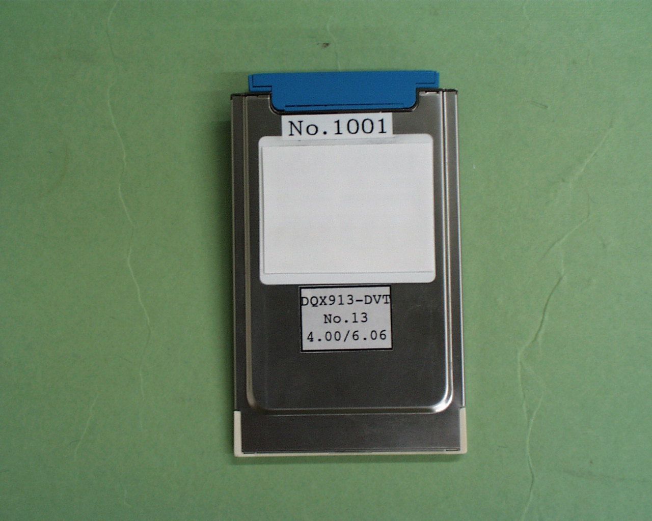
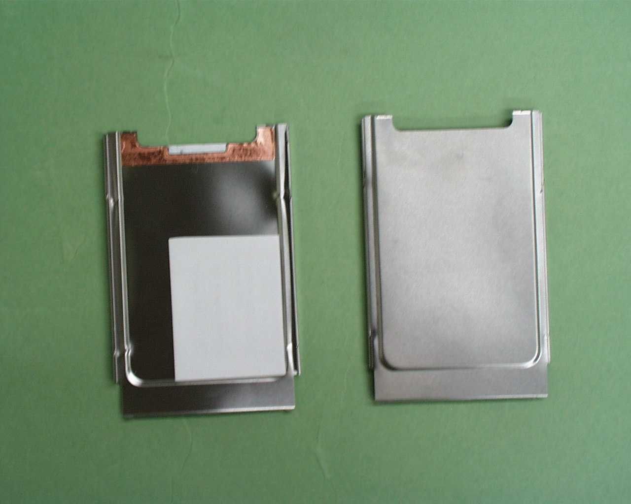
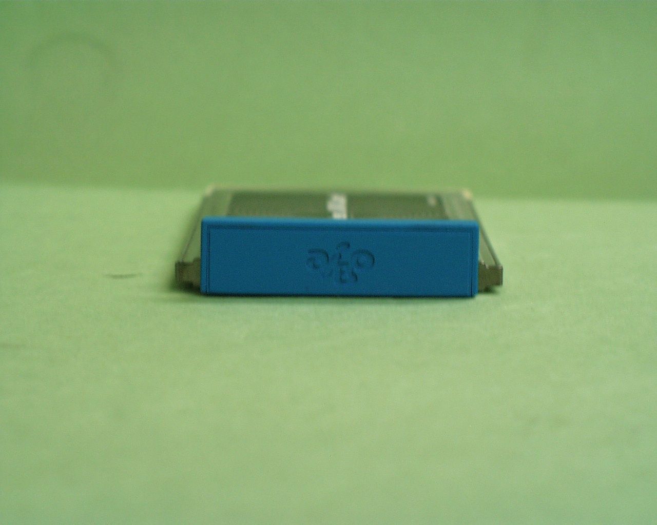
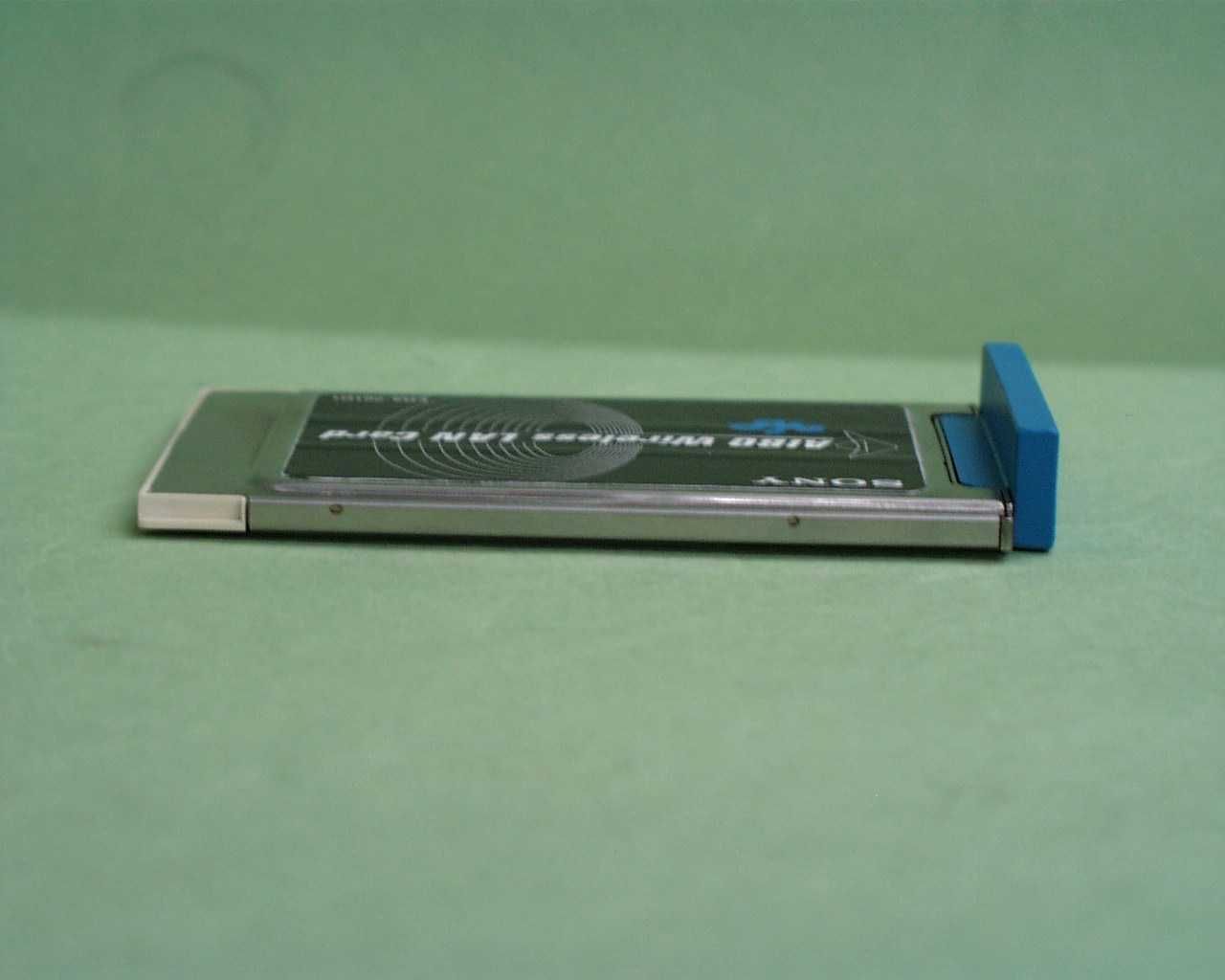
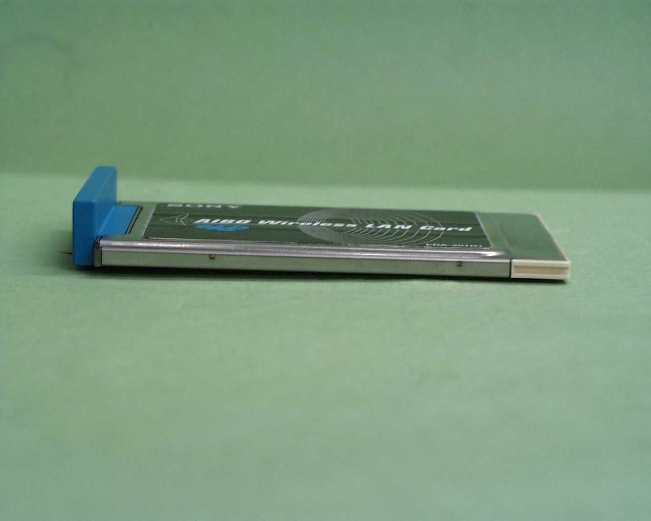
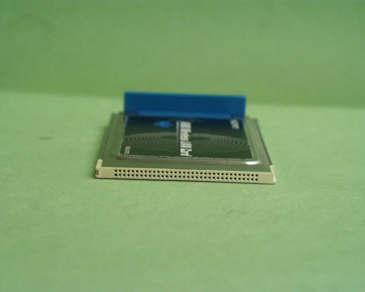
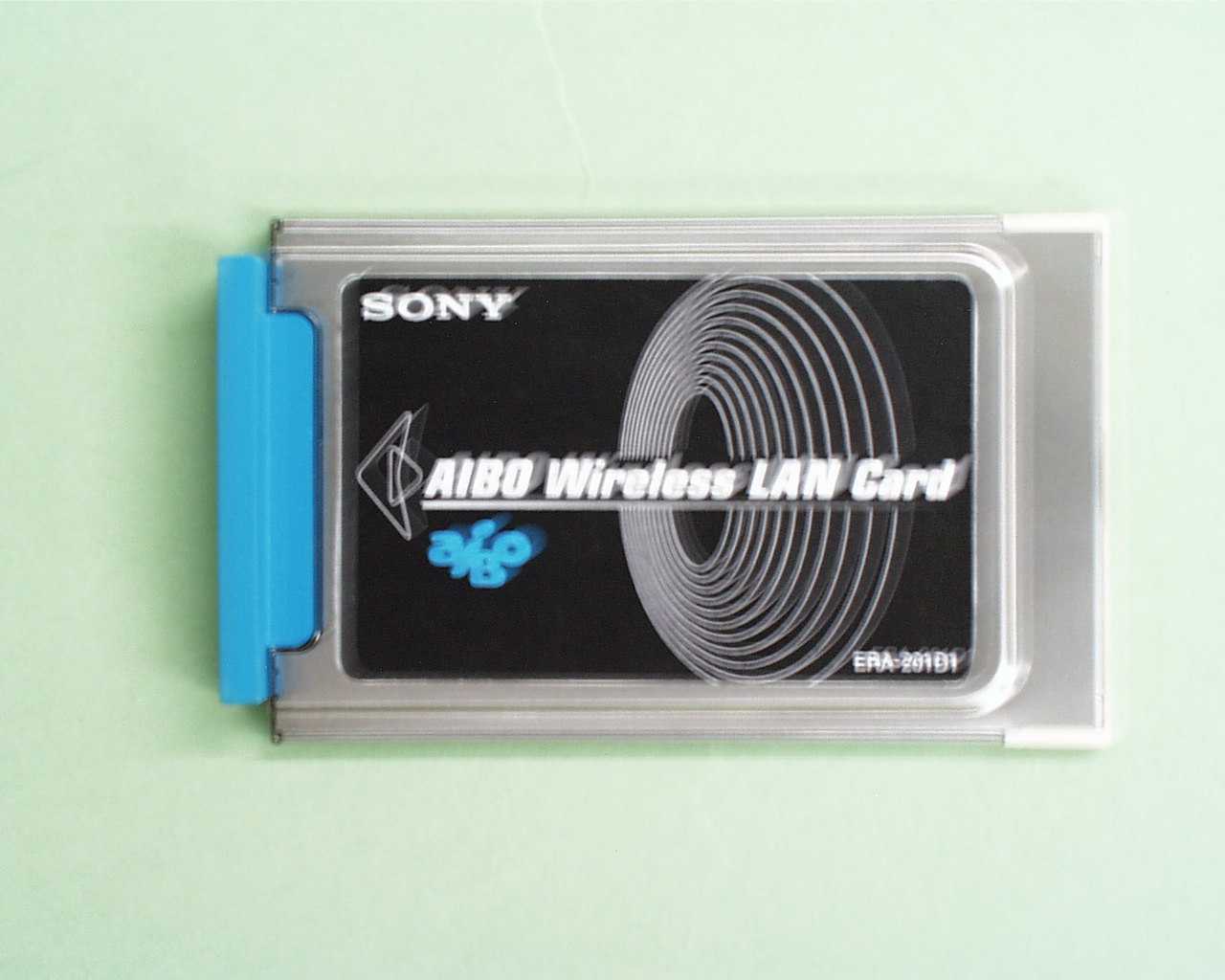
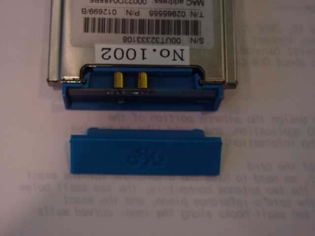
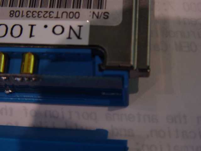
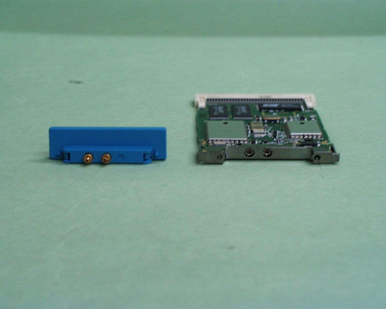
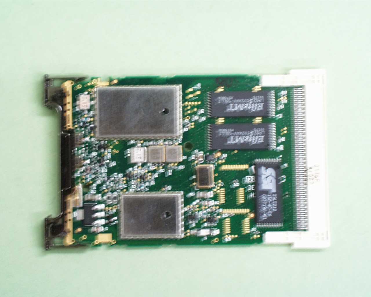
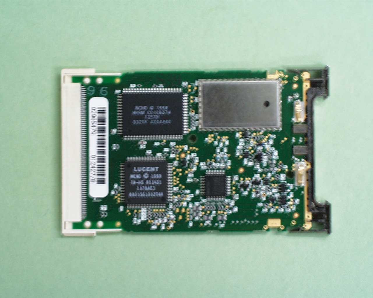
These photos show how Wireless LAN card is installed in the toy. Blue part in the body of toy is an antenna of the wireless LAC card “ERA-201D1”. This picture shows positional relativity of the Wireless LAN card and its antenna. To install the wireless card completely, the card has to be slide vertically into the body. These photos show the minimum distance 1.78 cm from the surface of the toy to the antenna of the wireless LAN card. Please refer the first page of this file in detail. Please note that the wireless LAN card and its Antenna is covered by enclosure of the toy when the wireless LAN card is fully installed as the above picture shows.
RF Exposure Info
FCCID: AK8ERA-201D1 AIBO WIRELESS LAN CARD Transmitting conditions of AIBO robot A duty cycle of a wireless LAN card in the AIBO robot is not constant depending on application software. Transmitting time is long in case of much data to be transmitted, but if there is no data to be transmitted, the transmission discontinues. In addition continuous transmission for a long time is not available because of overhead of the software. Usually, when any changes of robot status or a change of sensor information are produced, the robot initiates to transmit them and at the completion the transmission is intermitted. Transmitting DATA: 1. Status and conditions of robot 2. Information which robot monitors by sensors Transmitting duty cycle: Maximum : 30 percents Average : less than 20 percents
Test Report
Test report FCC ID : AK8ERA-201D1 Our reference : 21AE0018YW-1 Page: 2 of 17 Issued date: 2000-11-02 Testing Laboratory A-pex International Co., Ltd.Telephone:+81 596 39 1485 108 Yokowa-cho, Ise-shi Mie-ken 516-1106 JAPANFacsimile:+81 596 39 0232 Table of Contents Page 1 GENERAL INFORMATION3 1.1 Tested Methodology4 1.2 Test Facility4 2 PRODUCT DESCRIPTION5 2.1Test system Details5 2.2 Test system Details(Conducted emission and Radiated emission 30-1000MHz)6 3 SYSTEM TEST CONFIGURATION7 3.1 Justification7 3.2.1 Configuration of Tested System(2.1)7 3.2.2 Configuration of Tested System(2.2)8 3.3 Radiated Measurement Photos(30MHz to 1000MHz)9 3.4 Radiated Measurement Photos(1GHz to 26GHz)10 3.5 Conducted Power and Bandwidth Measurement Photos11 3.6 Conducted Measurement Photos12 4 MEASUREMENT UNCERTAINTY13 5 SUMMARY OF TEST14 5.1 Section 15.247(a)(2)Bandwidth14 5.2 15.247(b) Maximum Peak Out Put Power(Radiated and Conducted)14 5.3 15.247(c) Out of Band Emissions and Restricted Band Radiation14 5.4 15.247(d) Power Density(Conducted)14 5.5 15.207 Conducted Emissions15 5.6 15.247(e) Processing Gain15 6 TEST EQUIPMENT USED16 APPENDIX17 Test data A1 - A35 Test report FCC ID : AK8ERA-201D1 Our reference : 21AE0018YW-1 Page: 3 of 17 Issued date: 2000-11-02 Testing Laboratory A-pex International Co., Ltd.Telephone:+81 596 39 1485 108 Yokowa-cho, Ise-shi Mie-ken 516-1106 JAPANFacsimile:+81 596 39 0232 1 GENERAL INFORMATION APPLICANT: Sony Corporation ADDRESS: 6-7-35 Kitashinagawa, Shinagawa-ku, Tokyo 141-0001 Japan Tel: +81-3-5777-5840 Fax: +81-3-5777-7909 REGULATION(S): FCC Part15 Subpart C, Section 15.247 MODEL NUMBER: ERA-201D1 SERIAL NUMBER: 1001 KIND OF EQUIPMENT: Wireless LAN Card TESTED DATE: September 20,21 and 23, 2000 : November 1 and 2, 2000 RECEIPT DATE OF SAMPLE : September 19, 2000 REPORT FILE NUMBER: 21AE0018YW-1 TEST SITE: A-PEX Yokowa No. 2 and 3 Open Test Sites Test report FCC ID : AK8ERA-201D1 Our reference : 21AE0018YW-1 Page: 4 of 17 Issued date: 2000-11-02 Testing Laboratory A-pex International Co., Ltd.Telephone:+81 596 39 1485 108 Yokowa-cho, Ise-shi Mie-ken 516-1106 JAPANFacsimile:+81 596 39 0232 1.1 Tested Methodology The measurement was performed according to the procedures in FCC/ANSI C63.4(1992). 1.2 Test Facility The open area site measurement facilities used to collect the radiated data are located at 108, Yokowa-cho, Ise-shi, Mie-ken, 516-1106 Japan. These sites have been fully described in reports submitted to the FCC office. No.2 test site has filed to the FCC on October 26, 2000 as number: 90411 and is accepted by Industry Canada on February 19, 1998 as number IC2973-2. No.3 test site has filed to the FCC on September 12, 2000 as number: 90412 and is accepted by Industry Canada on February 19, 1998 as number IC2973-3. Test report FCC ID : AK8ERA-201D1 Our reference : 21AE0018YW-1 Page: 5 of 17 Issued date: 2000-11-02 Testing Laboratory A-pex International Co., Ltd.Telephone:+81 596 39 1485 108 Yokowa-cho, Ise-shi Mie-ken 516-1106 JAPANFacsimile:+81 596 39 0232 2 PRODUCT DESCRIPTION Sony Corporation, Model ERA-201D1 (referred to as the EUT in this report) is a Wireless LAN Card. The specification is as following : Clock frequency: 704MHz VCO (for upmixer) : 2050-2150MHz VCO (for upmixer) : 22MHz (for DSP) Carrier frequency: Direct sequence spread spectrum. 2412 through 2462MHz (11channels / each 5MHz wide) * Integral Antenna.(Antenna Gain: -3.6dBi) Operation Voltage: DC 3.3V I/F: PCMCIA-bus 2.1 Test System Details Model FCC ID Description Sony AK8ERA-201D1 Wireless LAN Card M/N: ERA-201D1 S/N: 1001 (EUT) Sony DOC Notebook Computer M/N: PCG-C1XG S/N:1107155 SonyDOCAC Adaptor M/N:PCGA-AC5N S/N: 0060941 SonyDOCFloppy Disk Drive M/N: PCGA-UFD5 S/N:2027779 Test report FCC ID : AK8ERA-201D1 Our reference : 21AE0018YW-1 Page: 6 of 17 Issued date: 2000-11-02 Testing Laboratory A-pex International Co., Ltd.Telephone:+81 596 39 1485 108 Yokowa-cho, Ise-shi Mie-ken 516-1106 JAPANFacsimile:+81 596 39 0232 2.2 Test System Details(Conducted emission and 15.209 Radiated emission 30-1000MHz) Model FCC ID or DOC Description Cable description Backshell Material (1) Sony N/A Wireless LAN Card - - M/N:ERA-201D1 (EUT) S/N:1001 (2) Sony DOC Notebook Computer Unshielded DC CableP.V.C. M/N:PCG-C1XG S/N:1107155 (3) Sony DOC AC Adapter Unshielded AC CableP.V.C. M/N:PCGA-AC5N S/N:0060941 (4) Sony N/A DV Camcorder Shielded DV CableP.V.C. M/N:DCR-PC100 Unshielded DC CableP.V.C. S/N:157422 (5) Sony N/A AC Adapter Unshielded AC CableP.V.C. M/N:AC-VQ800 S/N:21451028 (6) Sony DOC LCD Display Unshielded DC CableP.V.C. M/N:CPD-M151 Shielded VGA CableP.V.C. S/N:4515785 (7) Sony DOC AC Adapter Unshielded AC CableP.V.C. M/N:AC-L200 S/N:C712506110 (8) Sony DOC USB Mouse Shielded USB Mouse CableP.V.C. M/N:PCGA-UMS1 S/N:00500125* for Radiated emission. (8) Logitech DZL211137 USB Mouse Shielded USB Mouse CableP.V.C. M/N:M-UB48 S/N:LZA84550287* for Conducted emission. (9) Sony N/A Microphone Shielded Microphone CableP.V.C. M/N:ECM-717 S/N:- (10) Sony N/A Stereo Headphone Shielded StereoP.V.C. M/N:MDR-ED238ML Headphone Cable S/N:- (11) Victor N/A Telephone Switcher Unshielded TelephoneP.V.C. M/N:HC-T500P Switcher Cable S/N:- (12) Sony N/A Display Adapter Shielded Display Adapter CableP.V.C. M/N:PCGA-DA1 S/N:- Test report FCC ID : AK8ERA-201D1 Our reference : 21AE0018YW-1 Page: 7 of 17 Issued date: 2000-11-02 Testing Laboratory A-pex International Co., Ltd.Telephone:+81 596 39 1485 108 Yokowa-cho, Ise-shi Mie-ken 516-1106 JAPANFacsimile:+81 596 39 0232 3 SYSTEM TEST CONFIGURATION 3.1 Justification The system was configured in typical fashion (as a customer would normally use it) for testing. Operation mode : Data Transmitting Mode(11Mbps) Performed the test about channels 1(low), 6(mid) and 11(high) among 11 channels of all Carrier frequencies. Receiving mode Standby mode(Conducted emission only) * According to its specification, voltage supplied from host to this equipment is stable and hence this equipment dos…
Text truncated - open the document above for the full version.
Test Report
1 MEASUREMENT RESULTS OF DUTY RATIO OF AIBO WIRELESS LAN CARD Purpose: This report describes a measurement results regarding duty ratio of communications between ERA-201D1 AIBO wireless LAN card and a host computer in condition of typical application. Measurement Block Diagram: The measurement block diagram is shown as below: [A] : Hostname is “hirata03.erc.sony.co.jp” and connects to the Ethernet. [B] : Hostname is “900h-ice1.erc.sony.co.jp” and completes a connection to the IEEE 802.11b access point with the Ethernet over radio. [C] : This computer monitors communications between the host computer and the AIBO. Conditions of Communication Test: The AIBO ERS-210 and AIBO wireless LAN card ERA-201D1 are supported communications each other using TCP/IP protocol. The measurement flow for the measurement is shown as below and a file with 6924 byte is transmitted on HTTP(Hyper Text Transfer Protocol). The flow shows the transmission from AIBO to the host computer and vice versa. Ethernet Windows PC [A] IEEE802.11b Compatible Access Point (Sony PCWA-A100) AIBO ERS-210 With ERA-201D1 Wireless LAN Card [B] Windows PC [C] (with Packet Dump Tool) 2 P C [A] AIBO[B] The maximum payload length of Ethernet(IEEE802.3) is 1460 bytes. In TCP transmission, when the receiver receive a data, the receiver side always returns the acknowledgement data. Transaction period between the host and AIBO is measured as time shown with bold line in above flow chart in condition of transmitting the maximum length packet from AIBO. Calculation procedure: Maximum transmitting duty ratio from AIBO is calculated as follows: (Max. Duty Ratio) = (Transmit Period for Maximum Payload Data) / (Transaction Period (described the previous page) ) AIBO wireless LAN card, ERA-201D1, is applicable to 4 transmitting speeds, 11, 5.5, 2 and 1 Mbps in accordance with IEEE802.11b. SYN SYN, ACK ACK GET ACK HTTP OK Transmit Data (1460bytes payload) ACK Transmit Data (1460bytes payload) ACK 3 The transmitting data comprise of those shown as following expression; (Transmitting Data Length) = (HR/DSSS Frame Length) + (Ethernet Frame Length) (HR/DSSS Frame Length) = 192bits --- (i) (Ethernet Frame Length) = (Ethernet Header Length) + (IP Header Length) + (TCP Header Length) + ( Payload Data ) = 14 + 20 + 20 + 1460 = 1514 bytes = 12112bits --- (ii) Where, transmitting period of HR/DSSS Frame Length of expression (i) is constant in 1Mbps transmission speed and transmitting period of Ethernet Frame Length of expression (ii) is variable with change of transmission speeds.----- (this period changes adaptively depending on radio condition) Therefore, transmitting period is calculated as follows: (transmitting period of data) = ( transmitting period of (i) ) + ( transmitting period of (ii) ) = 192 / 1.0 x 10 -6 + 12112 / ( transmitting speed [bps] ) = ( 192 + 12112 / ( transmitting speed [Mbps] ) ) [us] --- (iii) (1) 11Mbps transmitting speed (Transmitting Period) = 192 + 12112 / 11 = 1293us (2) 5.5Mbps transmitting speed (Transmitting Period) = 192 + 12112 / 5.5 = 2394us (3) 2Mbps transmitting speed (Transmit Period) = 192 + 12112 / 2 = 6248us (4) 1Mbps transmitting speed (Transmit Period) = 192 + 12112 / 1 = 12304us 4 Measurement result: Measurement result of ethereal tool is as below. SpeedTransaction Start Time [s] Transaction End Time [s] Transaction Period [s] (I) (End – Start) Max. Payload Transmit Period [s] (II) Duty Ratio ( (II) / (I) ) 11Mbps0.3246600.3498160.0251561293 x 10 -6 0.051 5.5Mbps0.3243020.3503050.0260032394 x 10 -6 0.092 2Mbps0.3336360.3581800.0245446248 x 10 -6 0.25 1Mbps1.8443161.8739280.02961212304 x 10 -6 0.42 Conclusion&Comment: Maximum Transmitting Duty Rate is variable depending on the communication speed of Wireless LAN card as below. 11Mbps: 5.1% < 30% 5.5Mbs: 9.2% < 30% 2Mbps: 25% < 30% 1Mbps: 42% > 30% (NOTE: 1Mbps Communication is unstable) Maximum Duty Rate of 30% that we indicated is the value of which stable transmitting is put into practice at the rate of 2Mbps, 5.5Mbps and 11Mbps. Transmitting rate of 1Mbps is an impracticable rate for this wireless LAN card because of transmitting error due to the unqualified transmitting. Also, if the transmitting error of frequent occurrence, transmitting window size of TCP is switched over to smaller rate by the regulation of its software. Therefore, transmission at maximum payload on 1Mbps is not carried out continuously. From a practical standpoint, performance faster than 2Mbps is considered reasonable and proper for this wireless LAN card. We hereby declare that the maximum duty rate of this device is 30%. In addition to the above, under conditions using actual application, data transmission from PC to the wireless LAN card in AIBO and data transmission from the wireless LAN card to PC are transmitted simultaneously. The duty rates in this report are maximum value based on this measurement method. Due to characteristic features of bi-directional transmission of this wireless LAN card, actual duty rate of this wireless LAN card is less than the rates measured and shown in this report. 5 Display of the measurement: 11Mbps 6 Display of the measurement: 5Mbps 7 Display of the measurement: 2Mbps 8 Display of the measurement:1Mbps
Contact Information
Applicant
Kazuyuki Hori(Chief EMC/RF Compliance Specialist)
Technical Contact
A-PEX INTERNATIONAL CO., LTD.Nobutoshi Ohkubo
[email protected]+81-596-24-6717
4383-326 Asama-cho · Ise-shi, Mie-ken · Japan
Non-Technical Contact
A-PEX INTERNATIONAL CO., LTD.Nobutoshi Ohkubo
[email protected]+81-596-24-6717
Test Firm
UL Japan, Inc.Kazunori Nishimura
Technical Specifications
| # | Rule Parts | Frequency Range | Power Output | Tolerance |
|---|---|---|---|---|
| 1 | 15C | 2.41 GHz - 2.46 GHz | 64.60 mW | ppm |
Other Applications from Sony Group Corporation
AK8WW81782
Aug 21, 2026Radio Equipment
Equipment Class
DSS - Part 15 Spread Spectrum TransmitterAK8CFIZCP2
Aug 03, 2026Wireless Controller
Equipment Class
DSS - Part 15 Spread Spectrum TransmitterAK8OEV321MUH
Apr 14, 2026LCD Monitor
Equipment Class
JAD - Part 15 Class A Digital DeviceAK8OEV431MUH
Apr 14, 2026LCD Monitor
Equipment Class
JAD - Part 15 Class A Digital DeviceAK8OEV271MUH
Apr 14, 2026LCD Monitor
Equipment Class
JAD - Part 15 Class A Digital Device