AK8GSX100Mini Hi-Fi Component System TMR-GSX100
Sony Group Corporation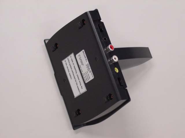
Click to zoom
Application Details
- Equipment Class
- DXX - Part 15 Low Power Communication Device Transmitter
- Date of Grant
- Jan 21, 2003
- Application Purpose
- Original Equipment
- Date of Application
- Jan 21, 2003
- Equipment Note
- Mini Hi-Fi Component System TMR-GSX100
- Frequency Range
- 913.50000000 - 914.50000000
- Company
- Sony Group Corporation
- Country
- Japan
Documents & Files
Document Text
Text extracted from the exhibit documents filed with the FCC. Open a document above to read the original.
Users Manual
model name1[MHC-GSX100W/MHC-GSX75] [4-245-586-11(1)] U2/CA2 filename[Y:\GSX1-3\4245586111\424558611MHCGSX100WU2\GB01COV-CEL.fm]masterpage:Right ©2003 Sony Corporation 4-245-586-11(1) Mini Hi-Fi Component System Operating Instructions Owner’s Record The model and serial numbers are located on the rear of the unit. Record the serial number in the space provided below. Refer to them whenever you call upon your Sony dealer regarding this product. Model No. ______________ Serial No. ______________ MHC-GSX100W MHC-GSX75 masterpage:Left filename[Y:\GSX1-3\4245586111\424558611MHCGSX100WU2\GB02REG-CELTOC.fm] 2 GB model name1[MHC-GSX100W/MHC-GSX75] [4-245-586-11(1)] U2/CA2 To prevent fire or shock hazard, do not expose the unit to rain or moisture. To prevent fire, do not cover the ventilation of the apparatus with news papers, table-cloths, curtains, etc. And don’t place lighted candles on the apparatus. To prevent fire or shock hazard, do not place objects filled with liquids, such as vases, on the apparatus. NOTICE FOR THE CUSTOMERS IN THE U.S.A. This symbol is intended to alert the user to the presence of uninsulated “dangerous voltage” within the product’s enclosure that may be of sufficient magnitude to constitute a risk of electric shock to persons. This symbol is intended to alert the user to the presence of important operating and maintenance (servicing) instructions in the literature accompanying the appliance. CAUTION The use of optical instruments with this product will increase eye hazard. Note to CATV system installer: This reminder is provided to call the CATV system installer’s attention to Article 820-40 of the NEC that provides guidelines for proper grounding and, in particular, specifies that the cable ground shall be connected to the grounding system of the building, as close to the point of cable entry as practical. WARNING This equipment has been tested and found to comply with the limits for a Class B digital device, pursuant to Part 15 of the FCC Rules. These limits are designed to provide reasonable protection against harmful interference in a residential installation. This equipment generates, uses, and can radiate radio frequency energy and, if not installed and used in accordance with the instructions, may cause harmful interference to radio communications. However, there is no guarantee that interference will not occur in a particular installation. If this equipment does cause harmful interference to radio or television reception, which can be determined by turning the equipment off and on, the user is encouraged to try to correct the interference by one or more of the following measures: – Reorient or relocate the receiving antenna. – Increase the separation between the equipment and receiver. – Connect the equipment into an outlet on a circuit different from that to which the receiver is connected. – Consult the dealer or an experienced radio/TV technician for help. CAUTION You are cautioned that any changes or modifications not expressly approved in this manual could void your authority to operate this equipment. NOTICE FOR THE CUSTOMERS IN CANADA CAUTION TO PREVENT ELECTRIC SHOCK, DO NOT USE THIS POLARIZED AC PLUG WITH AN EXTENSION CORD, RECEPTACLE OR OTHER OUTLET UNLESS THE BLADES CAN BE FULLY INSERTED TO PREVENT BLADE EXPOSURE. WARNING Do not install the appliance in a confined space, such as a bookcase or built-in cabinet. masterpage:Right filename[Y:\GSX1-3\4245586111\424558611MHCGSX100WU2\GB02REG-CELTOC.fm] 3 GB model name1[MHC-GSX100W/MHC-GSX75] [4-245-586-11(1)] U2/CA2 MHC-GSX100W only NOTICE FOR THE CUSTOMERS IN THE U.S.A. If you have any questions about this product, you may call; sony customer Information Center 1-800-488-7669 The Number below is for the FCC related matters only. Regulatory Information NOTICE FOR THE CUSTOMERS IN THE CANADA Operation is subject to the following two conditions: (1) this device may not cause interference, and (2) this device must accept any interference, including interference that may cause undesired operation of the device. NOTICE FOR THE CUSTOMERS IN THE U.S.A AND CANADA Replace the AC power adaptor with model AC-GSX100 only, if replacement is necessary. E NERGY STAR ® is a U.S. registered mark. As an E NERGY S TAR ® partner, Sony Corporation has determined that this product meets the E NERGY STAR ® guidelines for energy efficiency. Declaration of Conformity Trade Name:SONY Model No.:HCD-GSX100W Responsible Party:Sony Electronics Inc. Address:680 Kinderkamack Road, Oradell, NJ. 07649 USA Telephone No.:201-930-6972 This device complies with Part 15 of the FCC Rules. Operation is subject to the following two conditions: (1) This device may not cause harmful interference, and (2) this device must accept any interference received, including interference that may cause undesired operation. masterpage:Left filename[Y:\GSX1-3\4245586111\424558611MHCGSX100WU2\GB02REG-CELTOC.fm] 4 GB model name1[MHC-GSX100W/MHC-GSX75] [4-245-586-11(1)] U2/CA2 How to use this manual........................... 5 Playable discs.......................................... 5 Getting Started Hooking up the system............................ 7 Setting the clock...................................... 8 Wireless Hooking up the transmitter ..................... 9 (MHC-GSX100W only) Listening to audio using wireless system ............................................. 11 (MHC-GSX100W only) CD/MP3 – Play Loading a disc ....................................... 13 Playing a disc ........................................ 14 — Normal Play/Shuffle Play Playing repeatedly................................. 16 — Repeat Play Creating your own program .................. 16 — Program Play Labeling a disc ...................................... 17 — Disc Memo Tuner Presetting radio stations ........................ 19 Listening to the radio ............................ 20 — Preset Tuning — Manual Tuning Labeling the preset stations................... 21 — Station Name Tape – P…
Text truncated - open the document above for the full version.
Cover Letter(s)
American Telecommunications Certification Body Inc. 6731 Whittier Ave, McLean, VA 22101 January 21, 2003 RE: FCC ID: AK8GSX100 Attention: Sumio Nishii / Kanako Sanda I have a few comments on this Application. 1. The label and label area on the device appear more than sufficiently large enough to contain the 2- condition statement as required in 15.19(a)(3). Please provide a corrected label or please explain why the statement is not on the device. Please note that only those reasons provided in 15.19(a)(5) are acceptable or valid reasons not to place this statement on the product. While you may place the statement in the manual as well, it is required that, unless the exceptions of 15.19(a)(5) can be met, this statement MUST be on the product. Since this exception does not appear to apply to this device (i.e. it is large enough and there is sufficient room), please provide a corrected label with this statement. Dennis Ward mailto:[email protected] The items indicated above must be submitted before processing can continue on the above referenced application. Failure to provide the requested information may result in application termination. Correspondence should be considered part of the permanent submission and may be viewed from the Internet after a Grant of Equipment Authorization is issued. Please do not respond to this correspondence using the email reply button. In order for your response to be processed expeditiously, you must submit your documents through the AmericanTCB.com website. Also, please note that partial responses increase processing time and should not be submitted. Any questions about the content of this correspondence should be directed to the sender.
External Photos
External Photo(Transmitter) Sony EMCS Corporation FCC ID: AK8GSX100 front rear
ID Label/Location Info
Label Location (Transmitter) Sony EMCS Corporation FCC ID: AK8GSX100
Internal Photos
Internal Photo(Transmitter) Sony EMCS Corporation FCC ID: AK8GSX100 front with shield (Circuit Board) front without shield (Circuit Board) Internal Photo(Transmitter) Sony EMCS Corporation FCC ID: AK8GSX100 rear with shield (Circuit Board) rear without shield (Circuit Board) Internal Photo(Transmitter) Sony EMCS Corporation FCC ID: AK8GSX100 cover opened
Operational Description
Transmitter, TMR-GSX100 Circuit Description OUTLINE: TMR-GSX100 is a Transmitter of Sony Mini Hi-Fi Component System, MHC-GSX100W. This transmitter is operated within 913.5 - 914.5 MHz. CIRCUIT DESCRIPTION: As an example, suppose frequency of CH1, CH2 and CH3 are 913.5MHz, 914.0MHz and 914.5MHz respectively. When the audio input signals are inputted, Q401 detects them and Q402, 405,406 supplies the power to VCO UNIT. If there are no audio input signals over five minutes, the power to VCO UNIT is stopped. The audio input signals (L,R) are amplified at ALC AMP in IC401and pass through 75μs PRE- EMPHASIS. L, R signals from 75μs PRE- EMPHASIS pass through Low-pass Filter which maximizes the attenuation at 19kHz and go to IC403, STEREO MODULATOR. In STEREO MODULATOR, MPX signal and PILOT signal (19kHz) are made and mixed to generate COMPOSITE signal. COMPOSITE signal goes to VCO UNIT and is frequency-modulated at MOD in Q501. By selecting CH1, CH2, CH3 (S402), DC voltage inputted to VCO UNIT changes. And the carrier frequency from DR (Dielectric Resonator) OSC is fixed by this deviation of DC voltage. When switching CH1, CH2, CH3 (SW402), the carrier frequency and DC voltage are as follows. CH1: 913.5 MHz at 3.5 V CH2: 914.0 MHz at 2.8 V CH3: 914.5 MHz at 2.4 V Frequency-modulated signal is amplified by DRV AMP and is radiated at the above carrier frequency from the built-in antenna after passing through LPF.
Test Report
Test report No. : 23DE0077-HO-3 Page: 2 of 24 Issued date: January 15, 2003 FCC ID: AK8GSX100 A-Pex International Co., Ltd. EMC Head Office Division . 4383-326 Asama-cho, Ise-shi, Mie-ken 516-0021 JAPAN Telephone: +81 596 24 8116 Facsimile: +81 596 24 8124 CONTENTS PAGE SECTION 1: Client information 3 SECTION 2: Equipment under test (E.U.T.)3 SECTION 3: Test specification, procedures and results4 SECTION 4: Operation of E.U.T. during testing6 SECTION 5: Conducted Emission 7 SECTION 6: Radiated Emission (Fundamental and Spurious Emission) 8 APPENDIX 1: Photographs of test setup 9 APPENDIX 2: Test instruments 9 APPENDIX 3: Data of EMI test 9 Test report No. : 23DE0077-HO-3 Page: 3 of 24 Issued date: January 15, 2003 FCC ID: AK8GSX100 A-Pex International Co., Ltd. EMC Head Office Division . 4383-326 Asama-cho, Ise-shi, Mie-ken 516-0021 JAPAN Telephone: +81 596 24 8116 Facsimile: +81 596 24 8124 SECTION 1: Client information Company name: Sony EMCS Corporation Brand name: SONY Address: Sinagawa Intercity C tower Shinagawa Tec. 2-15-3, Konan Minato-ku, Tokyo, 108-6201, Japan Telephone Number: +81-3-5769-5293 Facsimile Number: +81-3-5769-5849 Contact Person: Shoji Kohara SECTION 2: Equipment under test (E.U.T.) 2.1Identification of E.U.T. Type of Equipment: Transmitter Model No.: TMR-GSX100 Serial No.: 1 Rating: TMR-GSX100 : DC IN 9.0V AC-GSX100 : Input:AC120V/ 60Hz, 4W Output : DC9V, 100mA Country of Manufacture: Korea Receipt Date of Sample : December 2, 2002 Condition of EUT: Engineering prototype 2.2Product Description TMR-GSX100 is a Transmitter of Sony Mini Hi-Fi Component System, MHC-GSX100W. The specification is as following Carrier Frequency: CH1:913.5MHz / CH2:914.0MHz / CH3:914.5MHz Type of Modulation: FM Antenna Type: Integral Antenna (Mono Pole Antenna) Test report No. : 23DE0077-HO-3 Page: 4 of 24 Issued date: January 15, 2003 FCC ID: AK8GSX100 A-Pex International Co., Ltd. EMC Head Office Division . 4383-326 Asama-cho, Ise-shi, Mie-ken 516-0021 JAPAN Telephone: +81 596 24 8116 Facsimile: +81 596 24 8124 SECTION 3: Test specification, procedures and results 3. 1Test Specification Test Specification: FCC Part 15 Subpart C Section 15.207 and Section15.249 Title: FCC 47CFR Part15 Radio Frequency Device Subpart C Intentional Radiators Section 15.207 Conducted emission limits; general requirements Section 15.249 Operation within the bands 902-928MHz, 2400-2483.5Mhz, 5725-5785MHz and 24.0-24.25GHz 3.2Procedures and results No.ItemTest ProcedureSpecificationDeviationWorst marginResults 1 Conducted Emission ANSI C63.4:2001Section 15.207(a)N/A27.7dB(0.4048MHz, L1):CH1Complied 2 Radiated Emission ANSI C63.4:2001Section 15.249N/A Fundamental 6.4dB(913.55MHz, Vertical): CH1 6.4dB(914.08MHz, Vertical): CH2 6.8dB(914.63MHz, Vertical): CH3 Spurious 12.8dB(3654.1MHz, Vertical): CH1 9.3dB(2742.0MHz, Vertical): CH2 7.2dB(2743.8MHz, Vertical): CH3 Complied 3.3Additions to standards No addition, deviation or exclusion has been made from standards. 3.4Confirmation A-Pex International Co., Ltd. hereby confirms that E.U.T. , in the configuration tested, complies with the specifications FCC Part15 Subpart C Section 15.207 and Section 15.249. 3.5Uncertainty Conducted emission test The measurement uncertainty (with a 95% confidence level) for this test was ±1.3dB. The data listed in this test report may exceed the test limit because it does not have enough margin. ■ The data listed in this test report has enough margin, more than the site margin. Radiated emission test The measurement uncertainty (with a 95% confidence level) for this test using Biconical antenna (3m) is ±4.5dB. The measurement uncertainty (with a 95% confidence level) for this test using Logperiodic antenna (3m) is ±5.2dB. The measurement uncertainty (with a 95% confidence level) for this test using Horn antenna (3m) is ±6.6dB. The data listed in this test report may exceed the test limit because it does not have enough margin. ■ The data listed in this test report has enough margin, more than the site margin. Test report No. : 23DE0077-HO-3 Page: 5 of 24 Issued date: January 15, 2003 FCC ID: AK8GSX100 A-Pex International Co., Ltd. EMC Head Office Division . 4383-326 Asama-cho, Ise-shi, Mie-ken 516-0021 JAPAN Telephone: +81 596 24 8116 Facsimile: +81 596 24 8124 3.6 Test Location A-Pex International Co., Ltd. EMC Head Office Division. No.1 semi anechoic chamber, 19.2 x 11.2 x 7.7m. A-Pex International Co., Ltd. EMC Head Office Division. No.2 semi anechoic chamber, 7.5 x 5.8 x 5.2m. 4383-326 Asama-cho, Ise-shi, Mie-ken 516-0021 JAPAN Telephone: +81 596 24 8116 Facsimile: +81 596 24 8124 This site has been fully described in a report submitted to FCC office, and listed on February 01, 2002 / June 05, 2002 (Registration number: 313583 / 846015). *NVLAP Lab. code: 200572-0 3.7Test setup, Data of EMI & Test instruments Refer to Appendix 1 to 3. Test report No. : 23DE0077-HO-3 Page: 7 of 24 Issued date: January 15, 2003 FCC ID: AK8GSX100 A-Pex International Co., Ltd. EMC Head Office Division . 4383-326 Asama-cho, Ise-shi, Mie-ken 516-0021 JAPAN Telephone: +81 596 24 8116 Facsimile: +81 596 24 8124 SECTION 5: Conducted emission 5.1Operating environment The test was carried out on a reference ground plane 4.0 x 4.0m in No.2 semi Anechoic Chamber, 7.5 x 5.8 x 5.2 m. Temperature: See data Humidity: See data 5.2Test configuration EUT was placed on a platform of nominal size, 1m by 1.5m, raised 80cm above the conducting ground plane. The rear of tabletop was located 40cm to the vertical conducting plane. The rear of EUT and its peripherals was aligned and flushed with rear of tabletop. All other surfaces of tabletop were at least 80cm from any other grounded conducting surface. EUT was located 80cm from LISN and excess AC cable was bundled in center. I/O cables that were connected to the peripherals were bundled in center. They were folded back and forth forming a bundle 30cm to 40cm long and were hanged at a 40cm height to the ground plane. Eac…
Text truncated - open the document above for the full version.
Test Setup Photos
Test report No. : 23DE0077-HO-3 Page: 10 of 24 Issued date: January 15, 2003 FCC ID: AK8GSX100 A-Pex International Co., Ltd. EMC Head Office Division . 4383-326 Asama-cho, Ise-shi, Mie-ken 516-0021 JAPAN Telephone: +81 596 24 8116 Facsimile: +81 596 24 8124 APPENDIX 1: Photographs of test setup Conducted emission Test report No. : 23DE0077-HO-3 Page: 11 of 24 Issued date: January 15, 2003 FCC ID: AK8GSX100 A-Pex International Co., Ltd. EMC Head Office Division . 4383-326 Asama-cho, Ise-shi, Mie-ken 516-0021 JAPAN Telephone: +81 596 24 8116 Facsimile: +81 596 24 8124 Radiated emission
Contact Information
Applicant
Kazuyuki Hori(Chief EMC/RF Compliance Specialist)
Technical Contact
A-Pex International Co., Ltd.Sumio Nishii
[email protected]81-596-24-8116
4383-326 Asama-cho · Ise-shi, Mie-ken · Japan
Non-Technical Contact
A-Pex International Co., Ltd.Kanako Sanda
[email protected]81-596-24-8116
Test Firm
UL Apex Co., Ltd.Tetsuya Hashimoto
Technical Specifications
| # | Rule Parts | Frequency Range | Power Output |
|---|---|---|---|
| 1 | 15C | 913.5 MHz - 914.5 MHz | - |
Other Applications from Sony Group Corporation
AK8WW81782
Aug 21, 2026Radio Equipment
Equipment Class
DSS - Part 15 Spread Spectrum TransmitterAK8CFIZCP2
Aug 03, 2026Wireless Controller
Equipment Class
DSS - Part 15 Spread Spectrum TransmitterAK8OEV321MUH
Apr 14, 2026LCD Monitor
Equipment Class
JAD - Part 15 Class A Digital DeviceAK8OEV431MUH
Apr 14, 2026LCD Monitor
Equipment Class
JAD - Part 15 Class A Digital DeviceAK8OEV271MUH
Apr 14, 2026LCD Monitor
Equipment Class
JAD - Part 15 Class A Digital Device