AK8HWSAV10TReceiver
Sony Group Corporation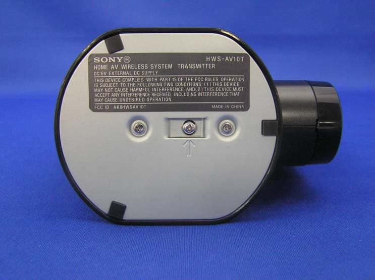
Click to zoom
Application Details
- Equipment Class
- CYY - Communications Receiver used w/Pt 15 Transmitter
- Date of Grant
- Jan 17, 2006
- Application Purpose
- Original Equipment
- Date of Application
- Jan 17, 2006
- Equipment Note
- Receiver
- Frequency Range
- 433.92000000 - 433.92000000
- Company
- Sony Group Corporation
- Country
- Japan
Documents & Files
Document Text
Text extracted from the exhibit documents filed with the FCC. Open a document above to read the original.
Users Manual
Home Wireless A/V System © 2006 Sony Corporation Operating Instructions Manual de instrucciones 2-674-819-01(1) HWS-AV10K ES US 2 US WARNING To reduce the risk of fire or electric shock, do not expose this apparatus to rain or moisture. Note You are cautioned that any changes or modifications not expressly approved in this manual could void your authority to operate this equipment. This transmitter must not be co-located or operated in conjunction with any other antenna or transmitter. This equipment complies with FCC radiation exposure limits set forth for uncontrolled equipment and meets the FCC radio frequency (RF) Exposure Guidelines in Supplement C to OET65. This equipment should be installed and operated with at least 20cm and more between the radiator and person’s body (excluding extremities: hands, wrists, feet and legs). Owner’s Record The model and serial numbers are located on the bottom of both units. Record the serial number in the space provided below. Refer to them whenever you call upon your Sony dealer regarding this product. Model number: HWS-AV10K Transmitter: HWS-AV10T Receiver: HWS-AV10R Serial number Transmitter: ___________________________ Receiver: ___________________________ 3 US Table Of Contents Features ........................................................................................................ 4 Preparing Checking the package contents ................................................................. 5 Identifying parts and controls ..................................................................... 6 Transmitter .............................................................................................................. 6 Receiver ................................................................................................................... 7 Preparing the transmitter ............................................................................ 8 Preparing the receiver ................................................................................. 9 Operating Watching A/V contents .............................................................................. 10 Improving reception ................................................................................... 11 To avoid the electromagnetic interference ............................................................ 11 Adjusting the dedicated antenna ........................................................................... 12 Installing the IR Blaster ............................................................................. 13 Others Troubleshooting ......................................................................................... 14 Precautions ................................................................................................. 16 Specifications ............................................................................................. 17 US 4 US Features Enjoy wireless transmission of stereo A/V contents in virtually any room of your house. Easily and wirelessly enjoy A/V contents playing in one room on a TV in another room. Just plug the transmitter into the A/V equipment you want to watch and plug the receiver into the TV in another room. PLAY PLAY ReceiverReceiver TransmitterTransmitter Receiver Transmitter •Wireless system eliminates the need for cables running between rooms. •Sony original 2.4 GHz wireless A/V transmission system. •4 selectable transmission channels (frequencies) for optimum reception. •Wireless remote control signal transmission, allowing remote control of transmitting A/V equipment from another room (remote control not supplied). •Remote control extender (IR Blaster) supplied to control A/V equipment in main room using an existing remote control. •Up to 100 ft. unobstructed signal reception (up to 60 ft. reception through most walls and floors). •Separate receiving dedicated antenna for excellent transmission. *As with all wireless products, actual performance will vary depending on environment. 5 US Preparing Checking the package contents After unpacking, check that all the following items have been included: •Transmitter: HWS-AV10T* (1) •Receiver: HWS-AV10R* (1) •Dedicated antenna (1) •IR Blaster (1) •AC power adaptor (2) •A/V cable (2) •Operating instructions (1) •To enjoy clear images and sounds (1) •Double sided seal (for IR Blaster) (1) •Warranty card (1) *The transmitter and receiver are the same shape. Check the label on the bottom of both units for the model name. 6 US Identifying parts and controls Transmitter Front 1 2 1Power indicator Lights when the transmitter is turned on. 2Power button Turns the transmitter power on and off. Rear CHANNEL VIDEO IN LEFT AUDIO IN RIGHT IR EXTENDER DC IN 6V 3 4 5 6 3CHANNEL switch* (page 11) Selects a desired channel (frequency) to transmit. 4VIDEO/AUDIO IN jacks (page 8) Connects the A/V cables to A/V equipment in main room. 5IR EXTENDER jack (page 13) Connects the IR Blaster (supplied). Do not connect the other of supplied IR Blaster. 6DC IN 6V jack (page 8) Connects the AC power adaptor (supplied). *Make sure to set the CHANNEL switch of the transmitter and receiver to the same position. 7 US Receiver Rear CHANNEL VIDEO OUT LEFT AUDIO OUT RIGHT ANT DC IN 6V b 4 5 6 7 4CHANNEL switch* (page 11) Selects a desired channel (frequency) to receive. 5VIDEO/AUDIO OUT jacks (page 9) Connects the A/V cables to your TV in another room. 6ANT jack (page 9) Connects the dedicated antenna. 7DC IN 6V jack (page 9) Connects the AC power adaptor (supplied). *Make sure to set the CHANNEL switch of the transmitter and receiver to the same position. Front 1 2 3 1Infrared receiver Receives the signal from the remote control. Point and operate the remote control of A/V equipment at here. 2Power indicator Lights when the receiver is turned on. 3Power button Turns the receiver power on and off. 8 US Preparing the transmitter Connect the A/V equipment in the main room to the transmitter and then turn on the trans…
Text truncated - open the document above for the full version.
External Photos
External Photo Sony Corporation Transmitter (Model: HWS-AV10T) FCC ID: AK8HWSAV10T Top Bottom External Photo Sony Corporation Transmitter (Model: HWS-AV10T) FCC ID: AK8HWSAV10T Front Back External Photo Sony Corporation Transmitter (Model: HWS-AV10T) FCC ID: AK8HWSAV10T Side 1 Side 2
ID Label/Location Info
Label location
Test Report
Test report No. : 26CE0198-YK-2 Page : 1 of 20 Issued date : January 12, 2006 UL Apex Co., Ltd. YAMAKITA EMC LAB. 907 Kawanishi, Yamakita-machi, Ashigarakami-gun, Kanagawa-ken, 258-0124 JAPAN Telephone: +81 465 77 1011 Facsimile: +81 465 77 2112 MF060b(01.06.05) EMI TEST REPORT Test Report No. : 26CE0198-YK-2 Applicant : Sony EMCS Corporation Saitama TEC Type of Equipment : Home AV Wireless System Transmitter Model No. : HWS-AV10T Test standard : FCC Part15 Subpart B Test Result : Complied 1. This test report shall not be reproduced except in full, without the written approval of UL Apex Co., Ltd. 2. The results in this report apply only to the sample tested. 3. This equipment is in compliance with above regulation. We hereby certify that the data contain a true representation of the EMC profile. 4. The test results in this test report are traceable to the national or international standards. Date of test: December 5, 2005 and January 6, 2006 Tested by: Makoto Hosaka Approved by: Osamu Watatani Site Manager of Yamakita EMC Lab. Test report No. : 26CE0198-YK-2 Page : 2 of 20 Issued date : January 12, 2006 UL Apex Co., Ltd. YAMAKITA EMC LAB. 907 Kawanishi, Yamakita-machi, Ashigarakami-gun, Kanagawa-ken, 258-0124 JAPAN Telephone: +81 465 77 1011 Facsimile: +81 465 77 2112 MF060b(01.06.05) CONTENTS PAGE SECTION 1 : Client information 3 SECTION 2 : Equipment under test (E.U.T.) 3 SECTION 3 : Test specification, procedures & results 4 SECTION 4 : Operation of E.U.T. during testing 6 SECTION 5 : Conducted emission 8 SECTION 6 : Radiated emission 9 Contents of appendixes 10 APPENDIX 1: Photographs of test setup 11 APPENDIX 2: Data of EMI test 13 APPENDIX 3: Test instruments 20 Test report No. : 26CE0198-YK-2 Page : 3 of 20 Issued date : January 12, 2006 UL Apex Co., Ltd. YAMAKITA EMC LAB. 907 Kawanishi, Yamakita-machi, Ashigarakami-gun, Kanagawa-ken, 258-0124 JAPAN Telephone: +81 465 77 1011 Facsimile: +81 465 77 2112 MF060b(01.06.05) SECTION 1: Client information Company Name : Sony EMCS Corporation Saitama TEC Address : Shinagawa INTERCITY C Tower Shinagawa Tec. 2-15-3 Konan Minato-ku, Tokyo, 108-6201 JAPAN Telephone Number : +81-3-5769-5640 Facsimile Number : +81-3-5769-5962 Contact Person : Kikuo Murata SECTION 2: Equipment under test (E.U.T.) 2.1 Identification of E.U.T. Type of Equipment : Home AV Wireless System Transmitter Model No. : HWS-AV10T Serial No. : 51 (Conducted emission), 18 (Radiated emission) Rating : : DC6V (AC120V/60Hz) Country of Manufacture : China Receipt Date of Sample : December 2 and 28, 2005 Condition of EUT : Engineering prototype (Not for Sale: This sample is equivalent to mass-produced items.) 2.2 Product description Model: HWS-AV10T (referred to as the EUT in this report) is a transmitter using 2408-2464 MHz and also a receiver using 433.92MHz of Home AV Wireless System HWS-AV10K. <Transmitter> Frequency of operation : 2408-2464 MHz Type of modulation : PSK Antenna type : Integral antenna Antenna connector type : None Antenna gain : 1.65 dBi Mode of operation : Simplex <Receiver> Frequency of operation : 433.92 MHz Local frequency : 431.7312 MHz Intermediate frequency : 2.1888 MHz Type of modulation : ASK Antenna type : Integral antenna Antenna connector type : None Method of Frequency generation : Crystal Emission designation : G1W Operation temperature range : 0 ~ 40 deg. C. Test report No. : 26CE0198-YK-2 Page : 4 of 20 Issued date : January 12, 2006 UL Apex Co., Ltd. YAMAKITA EMC LAB. 907 Kawanishi, Yamakita-machi, Ashigarakami-gun, Kanagawa-ken, 258-0124 JAPAN Telephone: +81 465 77 1011 Facsimile: +81 465 77 2112 MF060b(01.06.05) SECTION 3: Test specification, procedures & results 3.1 Test specification Test Specification : FCC Part 15 Subpart B Title : FCC 47CFR Part 15 Radio Frequency Device Subpart B Unintentional Radiators 3.2 Procedures & Results Item Test Procedure Limits DeviationWorst margin Result Conducted emission ANSI C63.4: 2003 7. AC powerline conducted emission measurements CISPR Pub.22 N/A 4.9dB (2.5139MHz, L1, AV) Complied Radiated emission ANSI C63.4: 2003 8. Radiated emission measurements FCC15.109 (a) N/A 9.8dB (50.10MHz, Vertical) Complied Antenna terminal voltage ANSI C63.4: 2003 Annex G.5 Antenna- conducted power measurement for receivers FCC15.111 (a) N/A *1 N/A N/A *1) The test is not applicable since the EUT has no antenna ports. Note: UL Apex’s EMI Work Procedures No. QPM05 3.3 Additions to standards No addition, deviation or exclusion has been made from standards. 3.4 Confirmation UL Apex Co., Ltd. hereby confirms the E.U.T., in the configuration tested, complies with the specifications FCC Part 15 Subpart B. 3.5 Uncertainty Conducted emission The measurement uncertainty (with 95% confidence level) for this test is ±2.7dB. The data listed in this test report has enough margin, more than site margin. Radiated emission The measurement uncertainty (with 95% confidence level) for this test using Biconical antenna is ±4.5dB. The measurement uncertainty (with 95% confidence level) for this test using Logperiodic antenna is ±4.3dB. The measurement uncertainty (with 95% confidence level) for this test using Horn antenna is ±5.2dB. The data listed in this test report has enough margin, more than site margin. Test report No. : 26CE0198-YK-2 Page : 5 of 20 Issued date : January 12, 2006 UL Apex Co., Ltd. YAMAKITA EMC LAB. 907 Kawanishi, Yamakita-machi, Ashigarakami-gun, Kanagawa-ken, 258-0124 JAPAN Telephone: +81 465 77 1011 Facsimile: +81 465 77 2112 MF060b(01.06.05) 3.6 Test Location UL Apex Co., Ltd. Yamakita EMC Lab. 907, Kawanishi, Yamakita-machi, Ashigarakami-gun, Kanagawa-ken 258-0124 JAPAN Telephone number: +81 465 77 1011 Facsimile number: +81 465 77 2112 NVLAP Lab. code: 200441-0 No. 1 test site has been fully described in a report submitted to FCC office, and accepted on August 26, 2005 (Registration No.: 95486). IC Registration No. : IC3489A No. 2 test site has been fully described in a report submitted to FCC office, and accepte…
Text truncated - open the document above for the full version.
Test Setup Photos
Test report No. : 26CE0198-YK-2 Page : 11 of 20 Issued date : January 12, 2006 UL Apex Co., Ltd. YAMAKITA EMC LAB. 907 Kawanishi, Yamakita-machi, Ashigarakami-gun, Kanagawa-ken, 258-0124 JAPAN Telephone: +81 465 77 1011 Facsimile: +81 465 77 2112 MF060b(01.06.05) Conducted emission Test report No. : 26CE0198-YK-2 Page : 12 of 20 Issued date : January 12, 2006 UL Apex Co., Ltd. YAMAKITA EMC LAB. 907 Kawanishi, Yamakita-machi, Ashigarakami-gun, Kanagawa-ken, 258-0124 JAPAN Telephone: +81 465 77 1011 Facsimile: +81 465 77 2112 MF060b(01.06.05) Radiated emission
Contact Information
Applicant
Kazuyuki Hori(Chief EMC/RF Compliance Specialist)
Technical Contact
UL Apex Co., LtdToyokazu Imamura
[email protected]81-465-77-1011
907 Kawanishi, Yamakita-machi · Ashigarakami-gun, Kanagawa-ken · Japan
Non-Technical Contact
UL Apex Co., LtdKeijiro Kumagai
[email protected]81-596-24-8116
Test Firm
UL Japan IncOsamu Watatani
Technical Specifications
| # | Rule Parts | Frequency Range | Power Output |
|---|---|---|---|
| 1 | 15B | 433.92 MHz - 433.92 MHz | - |
Other Applications from Sony Group Corporation
AK8WW81782
Aug 21, 2026Radio Equipment
Equipment Class
DSS - Part 15 Spread Spectrum TransmitterAK8CFIZCP2
Aug 03, 2026Wireless Controller
Equipment Class
DSS - Part 15 Spread Spectrum TransmitterAK8OEV321MUH
Apr 14, 2026LCD Monitor
Equipment Class
JAD - Part 15 Class A Digital DeviceAK8OEV431MUH
Apr 14, 2026LCD Monitor
Equipment Class
JAD - Part 15 Class A Digital DeviceAK8OEV271MUH
Apr 14, 2026LCD Monitor
Equipment Class
JAD - Part 15 Class A Digital Device