AK8ICBU655FRS Two-way Radio
Sony Group Corporation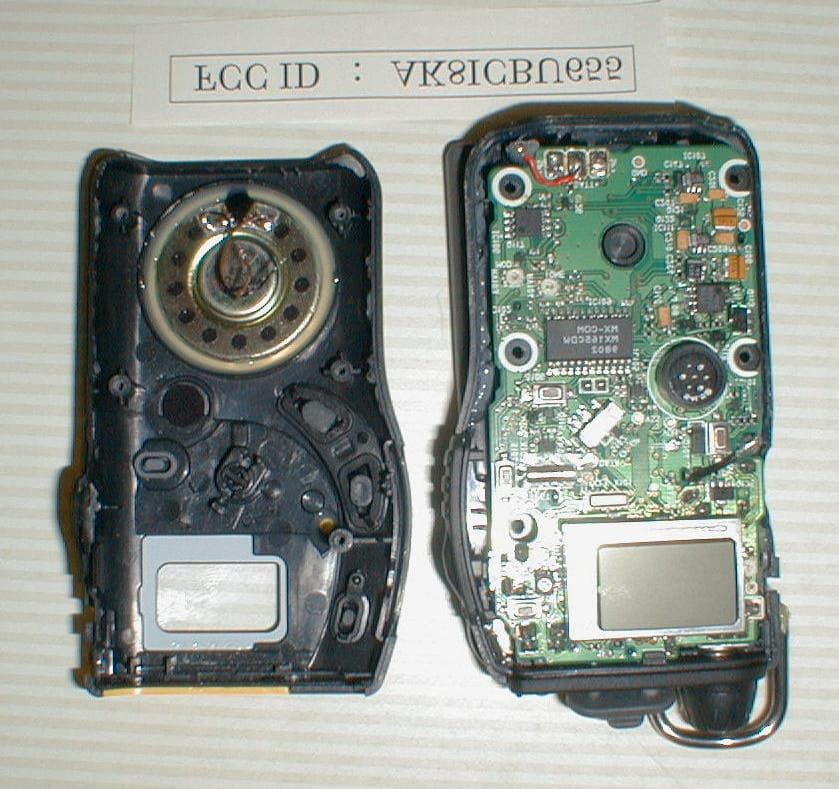
Click to zoom
Application Details
- Equipment Class
- FRF - Part 95 Family Radio Face Held Transmitter
- Date of Grant
- Apr 07, 1999
- Application Purpose
- Original Equipment
- Date of Application
- Jan 27, 1999
- Equipment Note
- FRS Two-way Radio
- Frequency Range
- 462.71250000 - 467.71250000
- Company
- Sony Group Corporation
- Country
- Japan
Documents & Files
Document Text
Text extracted from the exhibit documents filed with the FCC. Open a document above to read the original.
Users Manual
Sony Corporation © 1999 Printed in Japan Owner’s record The model and serial numbers are located in the battery compartment. Record the serial number in the space provided below. Refer to them whenever you call your Sony dealer regarding this product. Model No. ICB-U655 Serial No. _________________________ You are cautioned that any changes or modifications not expressly approved in this manual could void your authority to operate this equipment. INFORMATION This equipment has been tested and found to comply with the limits for a Class B digital device, pursuant to Part 15 of the FCC Rules. These limits are designed to provide reasonable protection against harmful interference in a residential installation. This equipment generates, uses, and can radiate radio frequency energy and, if not installed and used in accordance with the instructions, may cause harmful interference to radio communications. However, there is no guarantee that interference will not occur in a particular installation. If this equipment does cause harmful interference to radio or television reception, which can be determined by turning the equipment off and on, the user is encouraged to try to correct the interference by one or more of the following measures: — Reorient or relocate the receiving antenna. — Increase the separation between the equipment and receiver. — Connect the equipment into an outlet on a circuit different from that to which the receiver is connected. — Consult the dealer or an experienced radio/ TV technician for help. THIS DEVICE COMPLIES WITH PART 15 OF THE FCC RULES. OPERATION IS SUBJECT TO THE FOLLOWING TWO CONDITIONS: (1) THIS DEVICE MAY NOT CAUSE HARMFUL INTERFERENCE, AND (2) THIS DEVICE MUST ACCEPT ANY INTERFERENCE RECEIVED, INCLUDING INTERFERENCE THAT MAY CAUSE UNDESIRED OPERATION. Warning Never use this unit while skiing or during any other sport activity as it may lead to accidents or injury. Never use this unit in an airplane, as the electromagnetism from the unit may endanger flight safety. Caution Never use this unit near medical equipment without confirming safety and consent from due authorities. The electromagnetism from the unit may interfere with the equipment. In hospitals or in other medical facilities, turn off the power of this unit where use is prohibited. Before You Begin Thank you for choosing the Sony FRS Two-way radio! The unit will give you many hours of reliable service. Before operating the unit, please read these instructions thoroughly and retain them for future reference. Features The ICB-U655 is an FRS (Family Radio Service) two-way radio and can be used without any licences or qualifications within the United States. • A transmitting output of 500 mW, with 14 channels. Can communicate with other FRS two- way radios with the same frequency channels. • Handy size, easy to operate. • Group Talk feature — Allows you to communi- cate only with units on the same channel with the same group number, including other models with the same feature. • Search feature — Automatically searches for unused channels and calls up members of your group. • 180º rotating antenna for convenience and compactness. • Liquid Crystal Display to show operation status. Precautions Placement • Do not leave the unit near heat sources, such as radiators or air ducts, or in a place subject to direct sunlight, excessive dust, humidity, rain, mechanical vibration or shock. Do not leave the unit in a car parked in the sun, especially in the summer. • In vehicles or in buildings, transmission and reception may be difficult or noisy. Try using the unit near a window. Safety • Operate the unit on 4.5 V DC. For battery operation, use three size AA (R6) batteries. For car battery operation, use only the car battery cord recommended for this unit (not supplied). Do not use any other car battery cord. • When the unit is not to be used for a long time, remove the batteries to avoid possible damage caused by undue battery discharge, leakage or corrosion. • The nameplate indicating operating voltage, etc. is located at the rear exterior. • Should any solid object or liquid fall into the unit, remove the batteries and have the unit checked by qualified personnel before operating it any further. • Since a strong magnet is used for the speaker, metallic objects such as pins, etc. may cling to the unit. Keep personal credit cards using magnetic coding or spring-wound watches away from the unit to prevent possible damage from the magnet. • When the casing becomes soiled, clean it with a soft cloth dampened with mild detergent solution. Never use abrasive cleansers or chemical solvents, as they may mar the casing. • Keep the unit away from metallic objects. • Handle the antenna with care, so as not to bend or break it. Notes on using the two-way radio • Use this unit only within the United States of America in accordance with the regulations governing two-way radios in the United States of America. • Do not use this unit near a TV set, radio, or any type of broadcast station, as it may cause interference. • You are warned that your transmission could be heard by some other party. • Do not disclose or use the transmission of other parties in any form. • Two-way radios are not protected from interference by broadcast stations or other high frequency facilities. If you have any questions or problem concerning your unit, please consult your nearest Sony dealer. FRS Two-way Radio Operating Instructions 3-866-276-11 (1) ICB-U655 Troubleshooting Should any problem persist after you have made the following checks, consult your nearest Sony dealer. The power turns off unexpectedly. • The unit turned itself off by the Auto Power Off function (i.e., there was no reception or the unit was left unoperated for about 6 hours). Press POWER to turn the unit on again. • The batteries have gone out. Replace all batteries with new ones. The power does not turn on. • The batteries are not inserted with correct polarity. • The batterie…
Text truncated - open the document above for the full version.
External Photos
FCC ID : AK8ICBU655 Model : ICB-U655 Certification Photographs FCC ID : AK8ICBU655 Model : ICB-U655 Certification Photographs FCC ID : AK8ICBU655 Model : ICB-U655 Certification Photographs FCC ID : AK8ICBU655 Model : ICB-U655 Certification Photographs FCC ID : AK8ICBU655 Model : ICB-U655 Certification Photographs FCC ID : AK8ICBU655 Model : ICB-U655 Certification Photographs FCC ID : AK8ICBU655 Model : ICB-U655 Certification Photographs
Internal Photos
FCC ID : AK8ICBU655 Model : ICB-U655 Certification Photographs FCC ID : AK8ICBU655 Model : ICB-U655 Certification Photographs FCC ID : AK8ICBU655 Model : ICB-U655 Certification Photographs FCC ID : AK8ICBU655 Model : ICB-U655 Certification Photographs FCC ID : AK8ICBU655 Model : ICB-U655 Certification Photographs FCC ID : AK8ICBU655 Model : ICB-U655 Certification Photographs FCC ID : AK8ICBU655 Model : ICB-U655 Certification Photographs
Operational Description
FCC ID : AK8NTM30 Model : NTM-30 CIRCUIT DESCRIPTION of ICB-U655 ICB-U655 is a FRS(Family Radio Service) Tranceiver with 14 radio channels. 1ch 462.5625MHz 8ch 467.5625MHz 2ch 462.5875MHz 9ch 467.5875MHz 3ch 462.6125MHz 10ch 467.6125MHz 4ch 462.6375MHz 11ch 467.6375MHz 5ch 462.6625MHz 12ch 467.6625MHz 6ch 462.6875MHz 13ch 467.6875MHz 7ch 462.7125MHz 14ch 467.7125MHz Part RX Circuit system of ICB-U655(Part RX) is double conversion superheterodyne (lower heterodyne). An incoming RF signal received through the Antenna goes through the antenna switch (D1, D2, and D3) and is amplified at the RF Amplifier (Q1). The signal is converted to a first Intermediate Frequency (IF:21.7MHz) at a first mixer (IC1). The first Local Oscillator is a Phase Locked Loop (PLL) synthesized oscillator being varactor tuned, which is variable between 440.8625MHz to 446.0125MHz in RX mode. The first mixer is a Double Balanced Mixer (DBM). The first IF signal is amplified at a IF amplifier (Q2) and is converted to the second IF of 450kHz at a second Mixer in the IF IC (IC2). The second IF signal is demodulated at a FM demodulator in the IF IC (IC2). The demodulated signal input to the Tone generator/detector IC (IC109) by which the tone squelch circuit, de-emphasis, and HPF combine, and the tone squelch signal and AF (Audio Frequency) signal are separated in IC109. The AF signal is amplified at an AF Amplifier (IC102) and a Speaker connected to the AF Amplifier. Finally, the audible signal is heard through a internal speaker. FCC ID : AK8NTM30 Model : NTM-30 Part TX Circuit system of ICB-U655(Part TX) is Narrow band FM with varactor modulation. The frequency is made with Phase Locked Loop (PLL) synthesized oscillator composed of VCO1 and IC3, and will take a route to Q3, Q4, Q5, Q6 (P.A), Low Pass Filter and finally to the Antenna for the transmission. The transmission frequency is made by standard oscillator (Crystal Oscillator :X1 21.25MHz) and is adjusted by trimmer capacitor (C53). The transmission output is composed of the method of limiting the voltage given to Q4, Q5, and Q6, and is adjusted by RV107. The voltage limitation is controlled with IC103, Q124, and Q125. The aural signal picked up with the microphone (MIC101) is amplified by Q118 and sent to IC106. Amplifies, and pre- emphasis, LPF, and Modulation limit amplifier are composed in IC106. The IC106 output is adjusted maximum frequency deviation with RV103 to becoming in the standard, and is sent to varactor in VCO1 through LPF. Finally, modulated wave is transmitted through Antenna. SEARCH SYSTEM At the standby The channel is scanned while confirming whether there are both the 1kHz and the tone signal. The tone signal is CTCSS(Continuous Tone Controlled Sub-audible Squelch) signal set beforehand. When both 1kHz and the tone signal are detected, the scanning is stop. The 1kHz signal through the Amplifier (Q101) and the Schmitt-trigger (Q102, Q103) is sent to the System Controller (IC101). The 1kHz signal is detected by the System Controller and the tone signal is detected by IC109. FCC ID : AK8NTM30 Model : NTM-30 At the call The call operation starts when PTT is pushed at the standby mode. The call signal transmits automatically with an empty channel. The signal which is modulated by 1kHz and the tone signal is transmitted for several seconds. The 1kHz signal is generated by the System Controller and the tone signal is generated by IC109. The tone signal is CTCSS signal set beforehand. If there is no response for about ten seconds after call signal is transmitted, the unit returns to the standby mode.
Contact Information
Applicant
Kazuyuki Hori(Chief EMC/RF Compliance Specialist)
Technical Contact
Sony Electronics Inc.Julio Posse
201-930-6972
1 Sony Drive · Park Ridge, New Jersey · United States
Non-Technical Contact
Sony Electronics Inc.Julio Posse
[email protected]201-930-6972
Test Firm
Japan Quality Assurance Org.Fumio Nakamoto
Technical Specifications
| # | Rule Parts | Frequency Range | Power Output | Tolerance |
|---|---|---|---|---|
| 7 | - | 462.7125 MHz - 467.7125 MHz | 372.00 mW | 2.5 ppm |
Other Applications from Sony Group Corporation
AK8WW81782
Aug 21, 2026Radio Equipment
Equipment Class
DSS - Part 15 Spread Spectrum TransmitterAK8CFIZCP2
Aug 03, 2026Wireless Controller
Equipment Class
DSS - Part 15 Spread Spectrum TransmitterAK8OEV321MUH
Apr 14, 2026LCD Monitor
Equipment Class
JAD - Part 15 Class A Digital DeviceAK8OEV431MUH
Apr 14, 2026LCD Monitor
Equipment Class
JAD - Part 15 Class A Digital DeviceAK8OEV271MUH
Apr 14, 2026LCD Monitor
Equipment Class
JAD - Part 15 Class A Digital Device