AK8IRF302U2.4GHz/5GHz Band Wireless LANTransceiver
Sony Group Corporation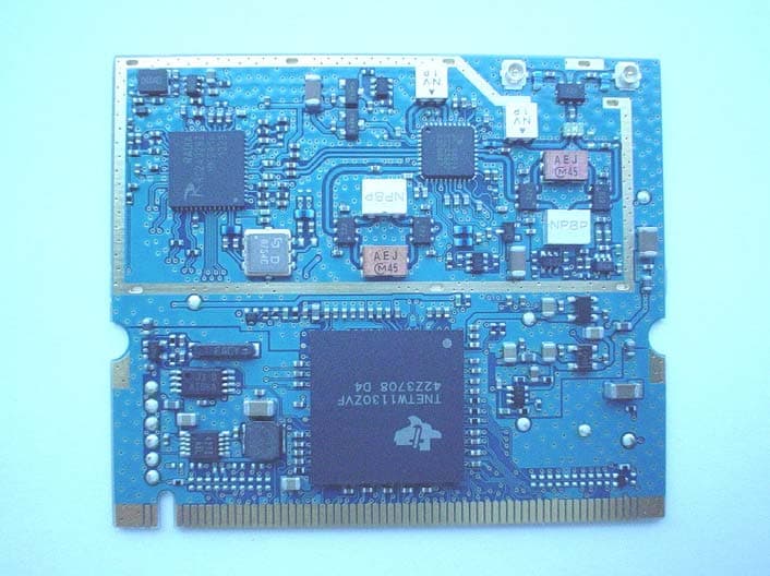
Click to zoom
Application Details
- Equipment Class
- NII - Unlicensed National Information Infrastructure TX
- Date of Grant
- Jul 01, 2004
- Application Purpose
- Original Equipment
- Date of Application
- Jul 01, 2004
- Equipment Note
- 2.4GHz/5GHz Band Wireless LANTransceiver
- Frequency Range
- 5745.00000000 - 5805.00000000
- Company
- Sony Group Corporation
- Country
- Japan
Documents & Files
Document Text
Text extracted from the exhibit documents filed with the FCC. Open a document above to read the original.
Users Manual
Installation Description IRF302U shall be installed in various kinds of Sony products. When IRF302U is installed in a product, we shall consider the following points; 1. Since IRF302U owns its FCC ID number, we shall affix an exterior label on the outside of the product if the FCC ID is not visible. The exterior label shall use wording such as either “Contains Transmitter Module FCC ID: AK8IRF302U” or “Contains FCC ID: AK8IRF302U “. 2. IRF302U complies with requirements of sub-sections 15.203, 15.205, 15.207, 15.247 and 15.407 in FCC Rules Part 15. We shall install IRF302U in accordance with their requirements. IRF302U complies with requirements of the sub-section 2.1091. When installers install IRF302U into a product, they shall ensure that the public is not exposed to radio frequency energy levels in excess of the Commission’s guidelines in accordance with the sub-section 15.247(b)(5) and 15.407(f) in FCC Rules Part 15. 3. Special Accessory (Shielded tape and Ferrite Core) must be patched for RF inference. Please refer to the following picture. 4. This equipment complies with FCC radiation exposure limits set forth for at uncontrolled equipment. This equipment should be installed and operated with minimum distance at least 20cm between the radiator and persons body (excluding extremities: hands, wrist, feet and legs) and must not be co-located or operated with any other antenna or transmitter. Shielded tape FerriteCore Ferrite Core Shielded tape Details of Ferrite Core Model: SFC-3 Manufacture: Kitagawa Industries Co., Ltd.
Users Manual
-1- IRF302U PRELIMINALY 2.4GHz/5GHz Band Wireless LAN Transceiver Unit General Description IRF302U, Dual band triple mode miniPCI Wireless LAN module, is compliant with 802.11a/b/g standard. IRF302U is designed for AV transmission, and it’s high performance enable 54Mbps high-bit data rate communication. Feature - Support QoS - Hardware-Based MAC Access Protocol - Low packet error rate Specifications - Host Interface: Mini PCI Standard 1.0 - Standard: IEEE802.11a/b/g compliant - Radio Signal Type: Direct Sequence Spread Spectrum (DSSS) Orthogonal Frequency Division Multiplexing (OFDM) - Wireless Data Rate: 802.11b=1/2/5.5/11Mbps 802.11g/a=6/9/12/18/24/36/48/54Mbps - Frequency Band: 2400-2483.5MHz / 5150-5350MHz / 5725-5825MHz - Channel Support: ch1-ch11 / ch34-ch64ch / ch149-ch161 - Data Modulation Techniques: BPSK (1Mbps), QPSK (2Mbps), CCK (5.5/11Mbps) OFDM (6/9/12/18/24/36/48/54Mbps) - Operating Range: 660ft (Outdoor, Line of sight) 100ft (Indoor) - Media Access Protocol: Ad-Hoc (Peer-to-Peer) Infrastructure - Security: WEP (Key Length 40/128/256bit) / AES / WPA (PSK) - Power Voltage: 3.3V (+/-5%) - Dimensions: 59.6 x 50.7 x 3.3mm - Weight: Approx.12g - Operating Temperature Range: -0C to +50C Sony reserves the right to change products and specifications without prior notice. This information does not convey any license by any implication or otherwise under any patents or other right. Application circuits shown, if any, are typical examples illustrating the operation of the devices. Sonycannot assume responsibility for any problems arising out of the use of these circuits. -2- IRF302U NOTIFICATION This equipment has been tested and found to comply with the limits for a Class B digital device, pursuant to Part15 of the FCC Rules. These limits are designed to provide reasonable protection against harmful interference in a residential installation. This equipment generates, uses, and can radiate radio frequency energy and, if not installed and used in accordance with the instructions, may cause harmful interference with radio communications. However, there is no guarantee that interference will not occur in a particular installation. If this equipment does cause harmful interference to radio or television reception, which can be determined by turning the equipment off and on, the use is encouraged to try to correct the interference by one or more of the following measures: Reoriented or relocate the receiving antenna. Increase the separation between the equipment and receiver. Connect the equipment into an outlet on a circuit different fromthat t which the receiver is connected. Consult the dealer or an experienced radio/TV technician for help. FCC WARNIG Changes or modifications not expressly approved by the party responsible for compliance could void the user’s authority to operate the equipment. For customers in the United States This product contains mercury. Disposal of this product may be regulated if sold in the United States. For disposal or recycling information, please contact your localauthorities or the Electronics Industries Alliance (http://eiae.org). This device complies with Part 15 of the FCC Rules. Operation is subjected to the following two conditions: (1)This device may not cause harmful interference, and (2)This device must accept any interference received, including interference that may cause undesired operation *This transmitter must not be co-located or operating in conjunction with any other antenna or transmitter. *When using the unit with 802.11a (5GHz), use in doors. FCC Radiation Exposure Statement: This equipment complies with FCC radiation exposure limits set forth for at uncontrolled equipment. This equipment should be installed and operated with minimum distance at least 20cm between the radiator and persons body (excluding extremities: hands, wrist, feet and legs) and must not be co-located or operated with any other antenna or transmitter. -3- IRF302U Electrical Characteristics Vdd=3.3V, Ta=25C SymbolMinTypMaxUnits Output powerP out2-20-dBm P out5-18-dBm Supply currentTx2.4GHzIddtx2-650-mA 5.2GHzIddtx5-760-mA Iddrx-370400mA ftol-100+10ppm Modulation AccuracyEVM2-4.3-% (64QAM)EVM5-5.0-% SensitivityRx_Sens2--71-dBm Rx_Sens5--70-dBm Packet Error RatePER2-0-% (-65dBm input ) PER5-0-% Parameter Center Frequency Tolerance 2.4GHz 5.2GHz Rx 2.4GHz (54Mbps) 5.2GHz (54Mbps) 2.4GHz (54Mbps) 5.2GHz (54Mbps) 2.4GHz (54Mbps) 5.2GHz (54Mbps) SymbolMinTypMaxUnits Output powerP out2-20-dBm P out5-18-dBm Supply currentTx2.4GHzIddtx2-650-mA 5.2GHzIddtx5-760-mA Iddrx-370400mA ftol-100+10ppm Modulation AccuracyEVM2-4.3-% (64QAM)EVM5-5.0-% SensitivityRx_Sens2--71-dBm Rx_Sens5--70-dBm Packet Error RatePER2-0-% (-65dBm input ) PER5-0-% Parameter Center Frequency Tolerance 2.4GHz 5.2GHz Rx 2.4GHz (54Mbps) 5.2GHz (54Mbps) 2.4GHz (54Mbps) 5.2GHz (54Mbps) 2.4GHz (54Mbps) 5.2GHz (54Mbps) Antenna - Model Name: SDA2452A -Type: Patch - Gain: 2.4GHz_Band : -1.0dBi(Typ) 5GHz_Band : +2.0dBi(Typ) - Connector Type: U.FL 2 0 . 0 3 0 . 0 20.0 30.0 1.25 6.3 ±0.2 0.6 6.0 -4- IRF302U Dimension 0.6 2.3 16.7 4 1.0 59.6 5.8 20 25.3 50.7 2-R2 3.6
Cover Letter(s)
American Telecommunications Certification Body Inc. 6731 Whittier Ave, McLean, VA 22101 June 28, 2004 RE: FCC ID: AK8IRF302U_ATCB001452 Attention: Hiroka Umeyama / Hisayuki Kioka I have a few comments on this Application. Please note that further comments may arise in response to answers provided to the questions below. 1. FYI. Please note that the definition of a Limited Modular Approval is a module that has been approved while tested in a specific host. Please note that this transmitter has not been tested in a specific host and is therefore not an LMA. It however, is a modular approval for use that is restricted to mobile devices only. Please note that the antenna cable used in the testing will not allow the device to be installed by the OEM or OEM integrator into any laptop of notebook computer. 2. Please note that the rf exposure statement in the OEM installation manual does not address the mobile only condition of this device. Please provide a manual which contains a caution to the OEM or OEM integrator that the device can only be installed in mobile devices which must maintain a minimum of 20 cm from the user. 3. Please note that as compliance of this device requires ferrites on the antenna cable. As the ferrites are used to reduce the emissions (standing waves) on the cable, and since it not know how these emissions may or may not be affected by cables of longer length, and as it has not been shown that a longer cable would be complaint under the same circumstances, the specific ferrites shown on the cable and the specific cable shown MUST be sold and installed as part of this device. Please note that this needs to be made clear in the installation guide as to how to install the ferrites and cable. 4. Please note that while the report states on page 10 that “cabling was taken into consideration”, it does specify what cables were considered. Were these the antenna cables? What was considered? If you have investigated the effects of longer cables with the ferrites and the transmitter, please provide evidence or clarification of such investigation. 5. Please note that the rf radiation statement in the manual is incorrect. Please note that the statement says the device was tested and found compliant. Please note that this is not the case. SAR nor MPE tested was performed. Only MPE calculations have been provided with this device to show that the 20cm distance is within MPE. Please correct your manual to remove the inference that the device has been tested for rf exposure and please provide the proper 20cm separation distance requirement in the manual. 6. Please note that as this device can only be installed by the OEM or OEM integrator, the installation manual must clearly indicate that the Host must have a label on the outside that clearly states “Contains TX FCC ID: AK8IRF302U” or similar. Please provide an OEM installation manual that provides this information to the OEM installer. 7. Please note that item 2 of the file “Installation Manual(IRF302U).pdf” states 15.247(b)(4) as an rf exposure limit. Please note that this is a power limit not an rf exposure limit. Please correct the document to reflect the proper rule part for rf exposure limits (i.e. 15.247(b)(5). 8. Please note that the report states that the peak conducted power was measured using an analyzer. Please note that when using an analyzer to make power measurements you must consider the resolution bandwidth correction factor. Please note that the plots show that the resolution bandwidth was only 1 MHz for these measurements. Please note that this mean an analyzer resolution bandwidth correction factor of 10log(OBW/res BW) must be used. For the 11Mhz OBW the correction factor would be 10log(11/1) or 10.4dB. for the 16MHz OBW the correction factor would be 10log(16.4/1) or 12.1dB. This means that the power reported in the conducted power measurements is significantly higher than reported. Please explain and please provide test data as specified in the FCC accepted measurement procedures for power measurements using an analyzer. Alternately, please explain why these numbers should be z Page 2 June 28, 2004 considered correct (i.e. does the analyzer account for the low resolution bandwidth in relation to the fundamental). 9. Please note that the Output power does not appear to have been measured in accordance with the accepted FCC techniques specified in DA-02-2138A1 (i.e. res bw = 1MHz; video bw=3MHz). Please explain. Dennis Ward mailto:[email protected] The items indicated above must be submitted before processing can continue on the above referenced application. Failure to provide the requested information may result in application termination. Correspondence should be considered part of the permanent submission and may be viewed from the Internet after a Grant of Equipment Authorization is issued. Please do not respond to this correspondence using the email reply button. In order for your response to be processed expeditiously, you must submit your documents through the AmericanTCB.com website. Also, please note that partial responses increase processing time and should not be submitted. Any questions about the content of this correspondence should be directed to the sender.
Cover Letter(s)
1 Dennis Ward From: [email protected] Sent: Wednesday, June 30, 2004 2:36 AM To: [email protected] Cc: [email protected] Subject: RE: Request for your reply-IRF302U[FCC ID:AK8IRF302U] Dear Dennis, Hello, we reply to your comment for AK8IRF302U, please confirm them. If you have any question, please let us know them by July 1st. About your comment 3, 4, 8 and 9, we are going to upload on your web site the revised test report July 2. Comment-1: Thank you for your kindly attention, we understood. Comment-2: We described rf exposure statement in the installation manual, and uploaded to your web site. Please confirm your web site. Comment-3: We made clear the installation place of ferrites regardless of the cable length. We submit the additional data (in long cable with ferrites : maximum length 20cm). Comment-4: The sentence means that the test was confirmed in the position of the maximum radiated emission level including the antenna and cables. And the revised sentence will be added in the report. Comment-5: We corrected rf exposure statement in the user's manual, and uploaded to your web site. Please confirm your web site. Comment-6: This statement has been described in the installation manual item1, please confirm it again. Comment-7: We corrected rf exposure limits in the installation manual, please confirm your web site. Comment-8: We followed the method 3 specified in DA-02-2138A1. The test was made with the spectrum analyzer that has a function of channel-power measurement. It covers the EBW range, that is, 40MHz mask. Therefore the correct peak conducted power is measured. The addional remarks will be added in the report. Comment-9: We followed the method 3 specified in DA-02-2138A1. The test was made with VBW, 1MHz(more than 1/T : T is a period of EUT transmitting ON = 370usec. ). The addional remarks will be added in the report. I look forward to hearing from you soon. Best regards, Hisayuki Kioka "dward ATCB" <[email protected]> 2004/06/29 07:02 Please respond to <[email protected]> To <[email protected]>, <[email protected]> 2 cc Subject RE: Request for your reply Hi Hisayuki / Hiroka Please see comments. I should have the other comments later today or tomorrow morning. There are probably some similar comments on both. Thanks Dennis -----Original Message----- From: [email protected] [mailto:[email protected]] Sent: Monday, June 28, 2004 7:20 AM To: [email protected] Cc: William Graff; [email protected]; [email protected]; [email protected] Subject: Fw: Request for your reply Dear Dennis, Hello, we uploaded 2 applications on your web site, so please confirm them. These applications are Limited Module Approval (LMA) as mobile equipment. *FCC ID: AK8IRF302U *FCC ID: AK8IRF303U If you have any question, please don't hesitate to contact us. Best regards, Hisayuki Kioka ----- Forwarded by Hisayuki Kioka/ISE/ULI on 2004/06/28 23:07 ----- Yukari Ito/ISE/ULI 2004/06/28 14:33 To <[email protected]> cc "William Graff" <[email protected]>, Hisayuki Kioka/ISE/ULI@ULI Subject RE: Request for your reply Dear Dennis, Thank you very much for your reply! Our Mr. Kioka will be very much glad to hear that ^ ^ We greatly appreciate your support and cooperation!! Best regards, Yukari ====================================================== YUKARI ITO (Ms.) Head Office EMC Lab., EMC Service Dept. UL Apex Co., Ltd. 4383-326 Asama-cho, Ise-shi, Mie-ken 516-0021 Japan 3 TEL: +81-(0)596-24-8116 FAX: +81-(0)596-24-8124 E-Mail: [email protected] URL: http://www.ulapex.jp "dward ATCB" <[email protected]> 2004/06/28 14:19 Please respond to <[email protected]> To <[email protected]> cc "William Graff" <[email protected]> Subject RE: Request for your reply Hi Yukari Thanks We will process the apps as quickly as possible. Dennis -----Original Message----- From: [email protected] [mailto:[email protected]] Sent: Sunday, June 27, 2004 4:51 PM To: [email protected] Cc: Mike Urban - ATCB; William Graff Subject: RE: Request for your reply Dear Dennis, Thank you very much for your reply to our new applications! Our Mr. Kioka will upload the applications today. Please kindly address the projects soon. Last Friday, I called ATCB office and a person(a guy) picked up the phone and he delivered my message to you and Bill. Please send my best regards and appreciation to the person. (I forgot to ask his name.... Or he might have mentioned his name, but I couldn't catch it.) Thank you so much for your support! Best regards, Yukari ====================================================== YUKARI ITO (Ms.) Head Office EMC Lab., EMC Service Dept. UL Apex Co., Ltd. 4383-326 Asama-cho, Ise-shi, Mie-ken 516-0021 Japan TEL: +81-(0)596-24-8116 FAX: +81-(0)596-24-8124 4 E-Mail: [email protected] URL: http://www.ulapex.jp "dward ATCB" <[email protected]> 2004/06/26 00:19 Please respond to <[email protected]> To <[email protected]> cc "Mike Urban - ATCB" <[email protected]>, "William Graff" <[email protected]> Subject RE: Request for your reply Hi Yukari In regards to your email about the two applications to be uploaded Monday: There should be no problem with the turnaround time as long as there is no technical or administrative problems with the application. Japan UL does a good job on the reports so this should not be a problem. Key items that might add time are: Rf exposure issues not properly addressed Manual not containing all the appropriate FCC regulatory notices Report data not clearly identified If modular - modular request letter addressing all 8 aspects These usually seem to be where 'snags' happen. Thanks Dennis -- For more information about UL, its Marks, and its services for EMC, quality registrations and product certifications for global markets, please access our web sites at http://www.ul.com and http://www.ul-asia.com, or contact your local sales representative. -- ********* Internet E-mail Confid…
Text truncated - open the document above for the full version.
External Photos
Photo Sony Corporation Model: IRF302U FCC ID: AK8IRF302U Front View of Wireless LAN Module Rear View of Wireless LAN Module Photo Sony Corporation Model: IRF302U FCC ID: AK8IRF302U Front View of Wireless LAN Module with Antenna and Shielding
Internal Photos
Photo Sony Corporation Model: IRF302U FCC ID: AK8IRF302U Front View of Wireless LAN Module Rear View of Wireless LAN Module Photo Sony Corporation Model: IRF302U FCC ID: AK8IRF302U Front View of Wireless LAN Module with Antenna and Shielding
RF Exposure Info
UL Apex Co., Ltd. Head Office EMC Lab. 4383-326 Asama-cho, Ise-shi, Mie-ken 516-0021 JAPAN Telephone : +81 596 24 8116 Facsimile : +81 596 24 8124 Applicant: Sony Corporation Type of Equipment: Wireless LAN Module Model No. : IRF302U FCC ID: AK8IRF302U RF Exposure Calculations: The following information provides the minimum separation distance for the highest gain antenna provided with the “IRF302U“ as calculated from FCC OET Bulletin 65 Appendix A, Table (B) Limits for General Population / Uncontrolled Exposure. This calculation is based on the highest EIRP possible from the system, considering maximum power and antenna gain, and considering a 1.0mW/cm^2 uncontrolled exposure limit. The Friis formula used was: S = (P * G) / (4* * r 2 ) Where P = 45.50mW (Maximum peak output power) G = 1.58Numerical Antenna gain; equal to2.00 r =20.0 cm For: IRF302U S =0.01435 mW/cm 2 No. : 24HE0082-HO-3 RF Exposure / SAR Statement
Test Report
Test report No. : 24HE0082-HO-3 Page : 2of 58 Issued date : June 25, 2004 FCC ID : AK8IRF302U UL Apex Co., Ltd. Head Office EMC Lab. 4383-326 Asama-cho, Ise-shi, Mie-ken 516-0021 JAPAN Telephone : +81 596 24 8116 Facsimile : +81 596 24 8124 MF060b(10.04.03) CONTENTS PAGE SECTION 1: Client information..........................................................................................................3 SECTION 2: Equipment under test (E.U.T.)........................................................................................3 SECTION 3: Test specification, procedures & results..........................................................................6 SECTION 4: Operation of E.U.T. during testing.................................................................................8 SECTION 5: Conducted Emission, Section 15.407(b)(6) / 15.207.......................................................10 SECTION 6: Spurious Emission , Band Edge Compliance 15.407(b)(1)(2)(3)(4)(6)(7).......................11 SECTION 7: 26dB Emission Bandwidth, Section 15.407(a)(1)(2)(3)...................................................12 SECTION 8: Peak Transmit Power, Section 15.407(a)(1)(2)(3)..........................................................12 SECTION 9: Peak Power Spectral Density, Section 15.407 (a)(1)(2)(3)..............................................12 SECTION 10: Peak Excursion Ratio, Section 15.407 (a)(6)................................................................12 APPENDIX 1: Photographs of test setup...........................................................................................13 Conducted Emission........................................................................................................................13 Spurious Emission (Radiated)..........................................................................................................14 Worst Case Position (Z-axis:Horizontal / Z-axis:Vertical)..................................................................15 APPENDIX 2:Test instruments...........................................................................................................16 APPENDIX 3: Data of EMI test..........................................................................................................17 Conducted Emission........................................................................................................................17 26dB Emission Bandwidth...............................................................................................................24 Peak Transmit Power.......................................................................................................................26 Radiated Spurious Emission (below 1GHz )......................................................................................28 Radiated Spurious Emission (above 1GHz:Inside of the restricted band)............................................34 Radiated Spurious Emission (above 1GHz:Outside of the restricted band).........................................44 Radiated emission Band Edge compliance.........................................................................................52 Conducted emission Band Edge compliance......................................................................................53 Peak Power Spectral Density............................................................................................................54 Peak Excursion Ratio.......................................................................................................................56 99%Occupied Bandwidth.................................................................................................................58 Test report No. : 24HE0082-HO-3 Page : 3of 58 Issued date : June 25, 2004 FCC ID : AK8IRF302U UL Apex Co., Ltd. Head Office EMC Lab. 4383-326 Asama-cho, Ise-shi, Mie-ken 516-0021 JAPAN Telephone : +81 596 24 8116 Facsimile : +81 596 24 8124 MF060b(10.04.03) SECTION 1: Client information Company Name : Sony Corporation Address : Gate City Osaki West Tower Osaki East Tec. 1-11-1 Osaki Shinagawa-ku, Tokyo, 141-0032 Japan Telephone Number : +81-3-5435-3977 Facsimile Number : +81-3-5436-3963 Contact Person : Masaki Nishimura SECTION 2: Equipment under test (E.U.T.) 2.1 Identification of E.U.T. Type of Equipment : Wireless LAN Module Model No. : IRF302U Serial No. : 125 (on Radiated and Conducted Emission Test) 77 (on Peak Transmit Power Test by Conducted) 11 (on Other Test by Conducted) Rating : DC3.3V 0.81A Country of Manufacture : Japan Receipt Date of Sample : May 31, 2004 Condition of EUT : Engineering prototype (Not for Sale: This sample is equivalent to mass-produced items.) Test report No. : 24HE0082-HO-3 Page : 4of 58 Issued date : June 25, 2004 FCC ID : AK8IRF302U UL Apex Co., Ltd. Head Office EMC Lab. 4383-326 Asama-cho, Ise-shi, Mie-ken 516-0021 JAPAN Telephone : +81 596 24 8116 Facsimile : +81 596 24 8124 MF060b(10.04.03) 2.2 Product Description The Sony model IRF302U is ISM and UNII transceiver module that is designed to provide a Wireless LAN access using 802.11b/g/a protocols for data rates of up-to 54Mbps. Normally the EUT is installed to Sony's "Wireless Location free TV". System clock : 40MHz [W-LAN:IEEE802.11a] Equipment Type : Transceiver Frequency of operation : 5180-5320MHz / 5745-5805MHz Channel Support : 5180,5200,5220,5240,5260,5280,5300,5320MHz / 5745,5765,5785,5805MHz Modulation Techniques : OFDM Channel number : 12channels Power control : Non Mode of operation : Duplex Antenna Type : Patch Antenna Antenna Gain : 2.0dBi(MAX) Antenna Connector Type : U.FL Operating voltage (inner) : DC3.3V Test report No. : 24HE0082-HO-3 Page : 5of 58 Issued date : June 25, 2004 FCC ID : AK8IRF302U UL Apex Co., Ltd. Head Office EMC Lab. 4383-326 Asama-cho, Ise-shi, Mie-ken 516-0021 JAPAN Telephone : +81 596 24 8116 Facsimile : +81 596 24 8124 MF060b(10.04.03) FCC 15.31 (e) This EUT provides stable voltage…
Text truncated - open the document above for the full version.
Test Report
Test report No. : 24HE0082-HO-3A Page : 2of 64 Issued date : June 30, 2004 FCC ID : AK8IRF302U UL Apex Co., Ltd. Head Office EMC Lab. 4383-326 Asama-cho, Ise-shi, Mie-ken 516-0021 JAPAN Telephone : +81 596 24 8116 Facsimile : +81 596 24 8124 MF060b(10.04.03) CONTENTS PAGE SECTION 1: Client information..........................................................................................................3 SECTION 2: Equipment under test (E.U.T.)........................................................................................3 SECTION 3: Test specification, procedures & results..........................................................................6 SECTION 4: Operation of E.U.T. during testing.................................................................................8 SECTION 5: Conducted Emission, Section 15.407(b)(6) / 15.207.......................................................10 SECTION 6: Spurious Emission , Band Edge Compliance 15.407(b)(1)(2)(3)(4)(6)(7).......................11 SECTION 7: 26dB Emission Bandwidth, Section 15.407(a)(1)(2)(3)...................................................12 SECTION 8: Peak Transmit Power, Section 15.407(a)(1)(2)(3)..........................................................12 SECTION 9: Peak Power Spectral Density, Section 15.407 (a)(1)(2)(3)..............................................12 SECTION 10: Peak Excursion Ratio, Section 15.407 (a)(6)................................................................12 APPENDIX 1: Photographs of test setup...........................................................................................13 Conducted Emission........................................................................................................................13 Spurious Emission (Radiated)..........................................................................................................14 Worst Case Position (Z-axis:Horizontal / Z-axis:Vertical)..................................................................15 APPENDIX 2:Test instruments...........................................................................................................16 APPENDIX 3: Data of EMI test..........................................................................................................17 Conducted Emission........................................................................................................................17 26dB Emission Bandwidth...............................................................................................................23 Peak Transmit Power.......................................................................................................................26 Radiated Spurious Emission (below 1GHz )......................................................................................28 Radiated Spurious Emission (above 1GHz:Inside of the restricted band)............................................34 Radiated Spurious Emission (above 1GHz:Outside of the restricted band).........................................44 Radiated emission Band Edge compliance.........................................................................................52 Conducted emission Band Edge compliance......................................................................................53 Peak Power Spectral Density............................................................................................................54 Peak Excursion Ratio.......................................................................................................................56 99%Occupied Bandwidth.................................................................................................................58 Test report No. : 24HE0082-HO-3A Page : 3of 64 Issued date : June 30, 2004 FCC ID : AK8IRF302U UL Apex Co., Ltd. Head Office EMC Lab. 4383-326 Asama-cho, Ise-shi, Mie-ken 516-0021 JAPAN Telephone : +81 596 24 8116 Facsimile : +81 596 24 8124 MF060b(10.04.03) SECTION 1: Client information Company Name : Sony Corporation Address : Gate City Osaki West Tower Osaki East Tec. 1-11-1 Osaki Shinagawa-ku, Tokyo, 141-0032 Japan Telephone Number : +81-3-5435-3977 Facsimile Number : +81-3-5436-3963 Contact Person : Masaki Nishimura SECTION 2: Equipment under test (E.U.T.) 2.1 Identification of E.U.T. Type of Equipment : Wireless LAN Module Model No. : IRF302U Serial No. : 125 (on Radiated and Conducted Emission Test) 77 (on Peak Transmit Power Test by Conducted) 11 (on Other Test by Conducted) Rating : DC3.3V 0.81A Country of Manufacture : Japan Receipt Date of Sample : May 31, 2004 Condition of EUT : Engin…
Text truncated - open the document above for the full version.
Contact Information
Applicant
Kazuyuki Hori(Chief EMC/RF Compliance Specialist)
Technical Contact
UL Apex Co., Ltd.Hiroka Umeyama
81-596-24-8116
4383-326 Asama-cho · Ise-shi, Mie-ken · Japan
Test Firm
UL Apex Co., Ltd.Tetsuya Hashimoto
Technical Specifications
| # | Rule Parts | Frequency Range | Power Output |
|---|---|---|---|
| 2 | 15E | 5.75 GHz - 5.80 GHz | 45.50 mW |
Other Applications from Sony Group Corporation
AK8WW81782
Aug 21, 2026Radio Equipment
Equipment Class
DSS - Part 15 Spread Spectrum TransmitterAK8CFIZCP2
Aug 03, 2026Wireless Controller
Equipment Class
DSS - Part 15 Spread Spectrum TransmitterAK8OEV321MUH
Apr 14, 2026LCD Monitor
Equipment Class
JAD - Part 15 Class A Digital DeviceAK8OEV431MUH
Apr 14, 2026LCD Monitor
Equipment Class
JAD - Part 15 Class A Digital DeviceAK8OEV271MUH
Apr 14, 2026LCD Monitor
Equipment Class
JAD - Part 15 Class A Digital Device