AK8MDRRF6500Wireless stereo headphones
Sony Group Corporation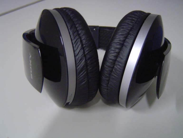
Click to zoom
Application Details
- Equipment Class
- DTS - Digital Transmission System
- Date of Grant
- Mar 01, 2011
- Application Purpose
- Original Equipment
- Date of Application
- Mar 01, 2011
- Equipment Note
- Wireless stereo headphones
- Frequency Range
- 2408.00000000 - 2473.00000000
- Company
- Sony Group Corporation
- Country
- Japan
Documents & Files
Document Text
Text extracted from the exhibit documents filed with the FCC. Open a document above to read the original.
Users Manual
Operating Instructions ______ Mode d’emploi ____________ Manual de instrucciones ____ Digital Surround Headphone System © 2011 Sony Corporation 4-267-263-72(1) MDR-DS6500 US FR ES _ 2 US WARNING To reduce the risk of fire or electric shock, do not expose this apparatus to rain or moisture. For customers in the USA Owner’s Record The model number is located at the bottom of the processor and both side of the headband. The serial number is located at the bottom of the processor and right inner side of the headband. Record these numbers in the spaces provided below. Refer to them whenever you call upon your Sony dealer regarding this product. Model No. MDR-DS6500 Processor DP-RF6500 Headphones MDR-RF6500 Serial No. Processor __________________________ Headphones ________________________ The following FCC statement applies only to the version of this model manufactured for sale in the USA. Other versions may not comply with FCC technical regulations NOTE This equipment must not be co-located or operated in conjunction with any other antenna or transmitter. NOTE This equipment has been tested and found to comply with the limits for a Class B digital device, pursuant to Part 15 of the FCC Rules. These limits are designed to provide reasonable protection against harmful interference in a residential installation. This equipment generates, uses and can radiate radio frequency energy and, if not installed and used in accordance with the instructions, may cause harmful interference to radio communications. However, there is no guarantee that interference will not occur in a particular installation. If this equipment does cause harmful interference to radio or television reception, which can be determined by turning the equipment off and on, the user is encouraged to try to correct the interference by one or more of the following measures: Reorient or relocate the receiving antenna. Increase the separation between the equipment and receiver. Connect the equipment into an outlet on a circuit different from that to which the receiver is connected. Consult the dealer or an experienced radio/ TV technician for help. For the state of California, USA only Perchlorate Material - special handling may apply, See www.dtsc.ca.gov/hazardouswaste/ perchlorate Perchlorate material: Lithium battery contains perchlorate CAUTION You are cautioned that any changes or modifications not expressly approved in this manual could void your authority to operate this equipment. − − − − 3 US For customers in Canada Operation is subject to the following two conditions: (1) this device may not cause interference, and (2) this device must accept any interference, including interference that may cause undesired operation of the device. This Class B digital apparatus complies with Canadian ICES-003. The following FCC/IC statement applies only to the version of this model manufactured for sale in the USA and Canada. Other versions may not comply with FCC/IC technical regulations. This headphones comply with FCC/IC radiation exposure limits set forth for an uncontrolled environment and meets the FCC radio frequency (RF) Exposure Guidelines in Supplement C to OET65 and RSS-102 of the IC radio frequency (RF) Exposure rules. This equipment has very low levels of RF energy that are deemed to comply without testing of specific absorption ratio (SAR). This processor complies with FCC/IC radiation exposure limits set forth for an uncontrolled environment and meets the FCC radio frequency (RF) Exposure Guidelines in Supplement C to OET65 and RSS-102 of the IC radio frequency (RF) Exposure rules. This processor has very low levels of RF energy that it deemed to comply without maximum permissive exposure evaluation (MPE). But it is desirable that it should be installed and operated keeping the radiator at least 20 cm or more away from person’s body (excluding extremities: hands, wrists, feet and ankles). US FOR UNITED STATES CUSTOMERS. NOT APPLICABLE IN CANADA, INCLUDING IN THE PROVINCE OF QUEBEC. POUR LES CONSOMMATEURS AUX ÉTATS-UNIS. NON APPLICABLE AU CANADA, Y COMPRIS LA PROVINCE DE QUÉBEC. This device complies with Part 15 of the FCC Rules. Operation is subject to the following two conditions: (1) this device may not cause harmful interference, and (2) this device must accept any interference received, including interference that may cause undesired operation. 4 US Table Of Contents Main Features ...................................5 Checking the Components and Accessories .....................................6 Location and Function of Parts........7 Processor Part Descriptions ....................... 7 Headphones Part Descriptions .................. 9 Charging the Headphones ............ 10 Checking the remaining battery power ...................................................... 12 Connecting the Headphone System ......................................... 13 Connecting the processor to digital components ............................................ 13 Connecting the processor to analog components ............................................ 14 Listening to a Connected Component ................................. 16 Replacing the Ear Pads .................. 23 Troubleshooting ............................ 24 Precautions .................................... 28 Specifications ................................. 29 5 US The MDR-DS6500 is a digital surround headphone system that allows you to enjoy the surround sound field of a BD/DVD or other multi-channel source wirelessly. You can enjoy multi-channel surround sound with headphones by simply connecting the digital surround processor to a BD/DVD device, digital satellite/TV receiver, GAME device or other device with the supplied cable. 7.1ch VPT (Virtualphones Technology) * 1 reproduces the three-dimensional surround of multi-channel speakers. Large size 40 mm driver units for premium movie theater sound quality. Wireless transmission means you can use these headphones anywhere indoors without …
Text truncated - open the document above for the full version.
External Photos
MDR-RF6500 Front Back Side Side To p Bottom
ID Label/Location Info
MDR-RF6500 Label and Label location
Internal Photos
MDR-RF6500 / Internal photos PWB of wireless block With shield case There are wireless parts on the opposite side. Without shield case
RF Exposure Info
UL Japan, Inc. Shonan EMC Lab. 1-22-3 Megumigaoka, Hiratsuka-shi, Kanagawa-ken, 259-1220 JAPAN Telephone: +81 463 50 6400 Facsimile: +81 463 50 6401 Applicant: Sony Corporation Type of Equipment : W ireless Stereo headphones Model No. : MDR-RF6500 FCC ID: AK8MDRRF6500 Sony Corporation declares that M odel : W ireless Stereo headphones complies with FCC radiation exposure requirement specified in the FCC Rules 2.1093. The “MDR-RF6500“ has 6.64 mW of conducted Peak Output power and 0.78 mW of EIRP. This kind of equipment is below 60/frequency[MHz] W (TCB Exclusion List) so that SAR testing is excluded. The Following calculation is the reference data for 20cm distance. RF Exposure Calculations: The following information provides the minimum separation distance for the highest gain antenna provided with the “M DR-RF6500“ as calculated from FCC OET Bulletin 65 Appendix A, Table (B) Limits for General Population / Uncontrolled Exposure. This calculation is based on the highest EIRP possible from the system, considering maximum power and antenna gain, and considering a 1.0mW/cm^2 uncontrolled exposure limit. The Friis formula used was: S = (P * G) / (4* π * r 2 ) Where P = 6.64 mW (M aximum peak output power) G = 0.12 Numerical Antenna gain; equal -9.28 dBi r =20.0 cm For: MDR-RF6500S = 0.00016 mW/cm 2 No. : 31DE0280-SH-01-B RF Exposure / SAR Statement
Test Report
Test report No. : 31DE0280-SH-01-B Page : 1 of 29 Issued date : January 31, 2011 Revised date : March 1, 2011 FCC ID : AK8MDRRF6500 UL Japan, Inc. Shonan EMC Lab. 1-22-3 Megumigaoka, Hiratsuka-shi, Kanagawa-ken, 259-1220 JAPAN Telephone : +81 463 50 6400 Facsimile : +81 463 50 6401 RADIO TEST REPORT Test Report No.: 31DE0280-SH-01-B Applicant : Sony Corporation Type of Equipment : Wireless Stereo Headphones Model No. : MDR-RF6500 FCC ID : AK8MDRRF6500 Test regulation : FCC Part15 Subpart C: 2010 Test result : Complied 1. This test report shall not be reproduced in full or partial, without the written approval of UL Japan, Inc. 2. The results in this report apply only to the sample tested. 3. This sample tested is in compliance with the limits of the above regulation. 4. The test results in this test report are traceable to the national or international standards. 5. This test report must not be used by the customer to claim product certification, approval, or endorsement by any agency of the Federal Government. 6. The opinions and the interpretations to the result of the description in this report are outside scopes where UL Japan has been accredited. Date of test: January 6 – 8, 2011 Tested by: ______________________________ Tatsuya Arai Engineer of WiSE Japan, UL Verification Service Approved by : ______________________________ Go Ishiwata Assistant Manager of WiSE Japan, UL Verification Service RTL02610 The testing in which "Non-accreditation" is displayed is outside the accreditation scopes in UL Japan. There is no testing item of "Non-accreditation". MF058d (12.01.11) Test report No. : 31DE0280-SH-01-B Page : 2 of 29 Issued date : January 31, 2011 FCC ID : AK8MDRRF6500 UL Japan, Inc. Shonan EMC Lab. 1-22-3 Megumigaoka, Hiratsuka-shi, Kanagawa-ken, 259-1220 JAPAN Telephone : +81 463 50 6400 Facsimile : +81 463 50 6401 Contents Page SECTION 1: Customer information ........................................................................................ 3 SECTION 2: Equipment under test (E.U.T.) .......................................................................... 3 SECTION 3: Test specification, procedures & results ........................................................... 5 SECTION 4: Operation of E.U.T. during testing .................................................................... 8 SECTION 5: Radiated emission ............................................................................................. 10 SECTION 6: Out of band emissions (Antenna port conducted) ......................................... 12 SECTION 7: 6dB bandwidth & Occupied bandwidth (99%) .............................................. 12 SECTION 8: Maximum peak output power .......................................................................... 12 SECTION 9: Peak power density ........................................................................................... 12 Contents of APPENDIXES ....................................................................................................... 13 APPENDIX 1: Photographs of test setup ............................................................................... 14 APPENDIX 2: Test data .......................................................................................................... 16 APPENDIX 3: Test instruments ............................................................................................. 29 Test report No. : 31DE0280-SH-01-B Page : 3 of 29 Issued date : January 31, 2011 Revised date : February 28, 2011 FCC ID : AK8MDRRF6500 UL Japan, Inc. Shonan EMC Lab. 1-22-3 Megumigaoka, Hiratsuka-shi, Kanagawa-ken, 259-1220 JAPAN Telephone : +81 463 50 6400 Facsimile : +81 463 50 6401 SECTION 1: Customer information Company Name : Sony Corporation Brand Name : Sony Address : Shinagawa INTERCITY C Tower, 2-15-3 Konan, Minato-ku, Tokyo 108-6201, Japan Telephone Number : +81-3-5769-5640 Facsimile Number : +81-3-5769-5996 Contact Person : Shigeru Higai SECTION 2: Equipment under test (E.U.T.) 2.1 Identification of E.U.T. Type of Equipment : Wireless Stereo Headphones Model No. : MDR-RF6500 Serial No. : Refer to the Section 4.2 Rating : DC3.7V Country of Mass-production : Malaysia Receipt Date of Sample : January 6, 2011 Condition of EUT : Engineering prototype (Not for Sale: This sample is equivalent to mass-produced items.) Modification of EUT : No Modification by the test lab 2.2 Product description Model No: MDR-RF6500, referred to as the EUT in this report, is the Wireless Stereo Headphones Model No: MDR-DS6500 is the Wireless Stereo Headphone System. MDR-DS6500 consists of DP-RF6500 (Digital Surround Processor) and MDR-RF6500 (Wireless Stereo Headphones). General Specification Clock frequency(ies) in the system : :DD converter 1.2MHz,Crystal 22.576649MHz, Master clock 11.2896MHz Radio Specification Equipment type : Transceiver Frequency of operation : 2408MHz-2473MHz Bandwidth & channel spacing : 3MHz & 5MHz Type of modulation : MSK Transmit power : 10mW Power control : None Method of frequency generation : Synthesize r Operating voltage (RF parts) : DC 2.5V Antenna type : Pattern Antenna Antenna Gain : ANT1: -9.7dBi, ANT2: -9.28dBi Antenna connector type : Integral Operation temperature range : 5 ~ +35 deg.C. Regulator : No Test report No. : 31DE0280-SH-01-B Page : 4 of 29 Issued date : January 31, 2011 FCC ID : AK8MDRRF6500 UL Japan, Inc. Shonan EMC Lab. 1-22-3 Megumigaoka, Hiratsuka-shi, Kanagawa-ken, 259-1220 JAPAN Telephone : +81 463 50 6400 Facsimile : +81 463 50 6401 FCC 15.31 (e) The EUT is a battery-operated device and test was performed with the full-charged battery. Therefore, this EUT complies with the requirement. FCC Part 15.203 It is impossible for end users to replace the antenna, because the antenna is mounted inside of the EUT. Therefore, the equipment complies with the antenna requirement of Section 15.203. Test report No. : 31DE0280-SH-01-B Page : 5 of 29 Issued date : January 31, 2011 Revised date : March 1, 201…
Text truncated - open the document above for the full version.
Test Report
Test Report No.: 31DE0280-SH-01-B Pa ge :16/ 29 Test placeUL Japan, Inc. Shonan EMC Lab. No.5 Shielded Room Date2011/1/8 Temperature / Humidity24deg.C./ 42% EngineerMakoto Hosaka ModeTx, , ANT 2 Transmitting(2473MHz) -6dB Bandwidth 2473.0000 -6dB Bandwidth Transmitting(2408MHz)Transmitting(2438MHz) Freq. [MHz] 2408.0000 2438.0000 > 0.500 Limi t [MHz] > 0.500 > 0.500 [MHz] 1.766 1.725 1.921 UL Japan, Inc. Shonan EMC Lab. 1-22-3 Megumigaoka, Hiratsuka-shi, Kanagawa 259-1220 JAPAN Telephone : +81 463 50 6400 Facsimile : +81 463 50 6401 Test Report No. : 31DE0280-SH-01-B Page :17/ 29 Test placeUL Japan, Inc. Shonan EMC Lab. No.2 Shielded Room Date2011/1/6 Temperature / Humidity23deg.C.45 % EngineerMakoto Hosaka ModeTx ANT 2 ChFreq.P/M (PK)CableAtten.Margin ReadingLossLoss [MHz][dBm][dB][dB][dBm][mW][dBm][mW][dB] Low2408.0-12.320.3820.168.226.6330.00100021.78 Mid2438.0-12.880.3920.157.665.8330.00100022.34 High2473.0-13.570.3920.156.974.9830.00100023.03 Sample Calculation: Result = Reading + Cable Loss (supplied by customer) + Atten. Loss * In the above table, factor 0.0dB represents no use of Atten. and/or Filter. *The test result is rounded off to one or two decimal places, so some differences might be observed. [Pre check] AntennaFreq.P/M (PK)CableAtten.Margin ReadingLossLoss [MHz][dBm][dB][dB][dBm][mW][dBm][mW][dB] 12438.0-13.120.3920.157.425.5230.00100022.58 22438.0-12.880.3920.157.665.8330.00100022.34 Peak Output Power (Conducted) ResultLimit ResultLimit UL Japan, Inc. Shonan EMC Lab. 1-22-3 Megumigaoka, Hiratsuka-shi, Kanagawa 259-1220 JAPAN Telephone : +81 463 50 6400 Facsimile : +81 463 50 6401 Test Report No.: 31DE0280-SH-01-B Page :18/ 29 Test plac eUL Japan, Inc. Shonan EMC Lab. No.2 Semi Anechoic Chamber Date Temperature / Humidit y19deg.C./35%18deg.C./25% Enginee r ModeTx, 2408 MHz , ANT 2 PolarityFrequencyDetectorReadingAnt.Fac.LossGainResultLimitMarginHeightAngle Remark [MHz][dBuV][dB/m][dB][dB][dBuV/m] [dBuV/m][dB][cm][deg.] Hori.112.900 QP35.111.98.031.823.243.520.3159319 Hori.186.276 QP35.816.38.831.729.243.514.3175315 Hori.218.909 QP31.016.89.031.725.146.020.9155297 Hori.278.053 QP34.118.89.531.730.746.015.311955 Hori.359.282 QP35.815.46.831.626.446.019.6100326 Hori.443.003 QP33.617.17.431.626.546.019.5100239 Hori.2362.650 P K47.127.313.537.150.873.923.1100161 Hori.2385.050 P K49.427.413.637.153.373.920.6100161 Hori.2390.000 P K46.527.413.637.050.573.923.4100161 Hori.2626.846 P K47.727.613.736.952.173.921.8100161 Hori.4816.000 P K55.630.65.835.956.173.917.8100316 Hori.7224.000 P K47.036.37.237.353.273.920.7154279 Hori.9632.000 P K43.738.48.335.654.873.919.11000 Hori.12040.000 P K45.139.49.436.957.073.916.91000 Hori.2362.650 A V38.227.313.537.141.953.912.0100161 Hori.2385.050 A V39.927.413.637.143.853.910.1100161 Hori.2390.000 A V35.927.413.637.039.953.914.0100161 Hori.2626.846 A V39.127.613.736.943.553.910.4100161 Hori.4816.000 A V48.630.65.835.949.153.94.8100316 Hori.7224.000 A V38.336.37.237.344.553.99.4154279 Hori.9632.000 A V31.338.48.335.642.453.911.51000 Hori.12040.000 A V33.139.49.436.945.053.98.91000 Vert.112.900 QP35.111.98.031.823.243.520.3100230 Vert.176.662 QP27.916.18.731.721.043.522.5100221 Vert.445.935 QP35.017.37.431.628.146.017.913421 Vert.2362.650 P K48.527.313.537.152.273.921.7100236 Vert.2385.050 P K50.727.413.637.154.673.919.3100236 Vert.2390.000 P K47.427.413.637.051.473.922.5100236 Vert.2626.846 P K47.127.613.736.951.573.922.4100236 Vert.4816.000 P K59.430.65.835.959.973.914.0155303 Vert.7224.000 P K45.636.37.237.351.873.922.1100272 Vert.9632.000 P K44.038.48.335.655.173.918.81000 Vert.12040.000 P K45.039.49.436.956.973.917.01000 Vert.2362.650 A V38.527.313.537.142.253.911.7100236 Vert.2385.050 A V41.127.413.637.145.053.98.9100236 Vert.2390.000 A V35.927.413.637.039.953.914.0100236 Vert.2626.846 A V38.727.613.736.943.153.910.8100236 Vert.4816.000 A V49.730.65.835.950.253.93.7155303 Vert.7224.000 A V36.136.37.237.342.353.911.6100272 Vert.9632.000 A V31.438.48.335.642.553.911.41000 Vert.12040.000 A V33.239.49.436.945.153.98.81000 Result = Reading + Ant Factor + Loss (Cable+Attenuator+Filter-Distance factor(above 13GHz)) - Gain(Amprifier) *Other frequency noises omitted in this report were not seen or have enough margin (more than 20dB). Distance factor:13GHz-40GHz20log(3.0m/1.0m)= 9.5dB 20dBc Data Sheet(RBW 100kHz, VBW 300kHz) PolarityFrequencyDetectorReadingAntLossGainResultLimitMarginRemark Factor [MHz][dBuV][dB/m][dB][dB][dBuV/m][dBuV/m][dB] Hori.2408.000 PK98.327.413.737.0102.4-- Carrier Hori.2400.000 PK49.027.413.737.053.182.429.3 Vert.2408.000 PK99.227.413.737.0103.3-- Carrier Vert.2400.000 PK48.627.413.737.052.783.330.6 Result = Reading + Ant Factor + Loss (Cable+Attenuator+Filter-Distance factor(above 13GHz)) - Gain(Amprifier) Radiated Emission 2011/1/62011/1/7 Tatsuya Ara iHikaru Shirasawa UL Japan, Inc. Shonan EMC Lab. 1-22-3 Megumigaoka, Hiratsuka-shi, Kanagawa 259-1220 JAPAN Telephone : +81 463 50 6400 Facsimile : +81 463 50 6401 Test Report No.: 31DE0280-SH-01-B Pa ge :19/ 29 Test placeUL Japan, Inc. Shonan EMC Lab. No.2 Semi Anechoic Chambe r Date Temperature / Humidity19deg.C./35%18deg.C./25% Enginee r ModeTx, 2438 MHz , ANT 2 PolarityFrequencyDetector ReadingAnt.Fac.LossGainResultLimitMarginHeightAngle Remark [MHz][dBuV][dB/m][dB][dB][dBuV/m] [dBuV/m][dB][cm][deg.] Hori.112.896 QP35.111.98.031.823.243.520.3160318 Hori.186.284 QP35.716.38.831.729.143.514.4178322 Hori.221.649 QP30.216.99.131.724.546.021.5141281 Hori.280.614 QP33.918.89.531.730.546.015.512655 Hori.358.580 QP36.015.56.831.626.746.019.3100323 Hori.443.285 QP33.317.17.431.626.246.019.8100237 Hori.2483.500 PK47.727.413.636.951.873.922.1100162 Hori.4876.000 PK56.730.75.835.957.373.916.6100317 Hori.7314.000 PK47.936.47.237.354.273.919.7156279 Hori.9752.000 PK42.138.58.335.853.173.920.81000 Hori.12190.000 PK44.039.49.536.956.073.917.91000 Hori.2483.500 A V36.427.413.636.940.553.913.4100162 Hori.4876.000 A V49.330.75.835.949.953.94.0100317 Hori.7314.000 A V39.336.47.237.345.653.98.…
Text truncated - open the document above for the full version.
Test Setup Photos
Test report No. : 31DE0280-SH-01-B Page : 14 of 29 Issued date : January 31, 2011 FCC ID : AK8MDRRF6500 UL Japan, Inc. Shonan EMC Lab. 1-22-3 Megumigaoka, Hiratsuka-shi, Kanagawa-ken, 259-1220 JAPAN Telephone : +81 463 50 6400 Facsimile : +81 463 50 6401 Radiated emission Test report No. : 31DE0280-SH-01-B Page : 15 of 29 Issued date : January 31, 2011 FCC ID : AK8MDRRF6500 UL Japan, Inc. Shonan EMC Lab. 1-22-3 Megumigaoka, Hiratsuka-shi, Kanagawa-ken, 259-1220 JAPAN Telephone : +81 463 50 6400 Facsimile : +81 463 50 6401 Worst Case Position X-axis Y-axis Z-axis
Contact Information
Applicant
Kazuyuki Hori(Chief EMC/RF Compliance Specialist)
Technical Contact
UL Japan, Inc.Go Ishiwata
[email protected]81-463-50-6400
1-22-3, Megumigaoka, Hiratsuka-shi · Kanagawa-ken · Japan
Test Firm
UL Japan, Inc. Shonan EMC EMC Lab.Tetsuya Hashimoto
Technical Specifications
| # | Rule Parts | Frequency Range | Power Output |
|---|---|---|---|
| 1 | 15C | 2.41 GHz - 2.47 GHz | 6.60 mW |
Other Applications from Sony Group Corporation
AK8WW81782
Aug 21, 2026Radio Equipment
Equipment Class
DSS - Part 15 Spread Spectrum TransmitterAK8CFIZCP2
Aug 03, 2026Wireless Controller
Equipment Class
DSS - Part 15 Spread Spectrum TransmitterAK8OEV321MUH
Apr 14, 2026LCD Monitor
Equipment Class
JAD - Part 15 Class A Digital DeviceAK8OEV431MUH
Apr 14, 2026LCD Monitor
Equipment Class
JAD - Part 15 Class A Digital DeviceAK8OEV271MUH
Apr 14, 2026LCD Monitor
Equipment Class
JAD - Part 15 Class A Digital Device