AK8MV65STDVD Player With FM Transmitter
Sony Group Corporation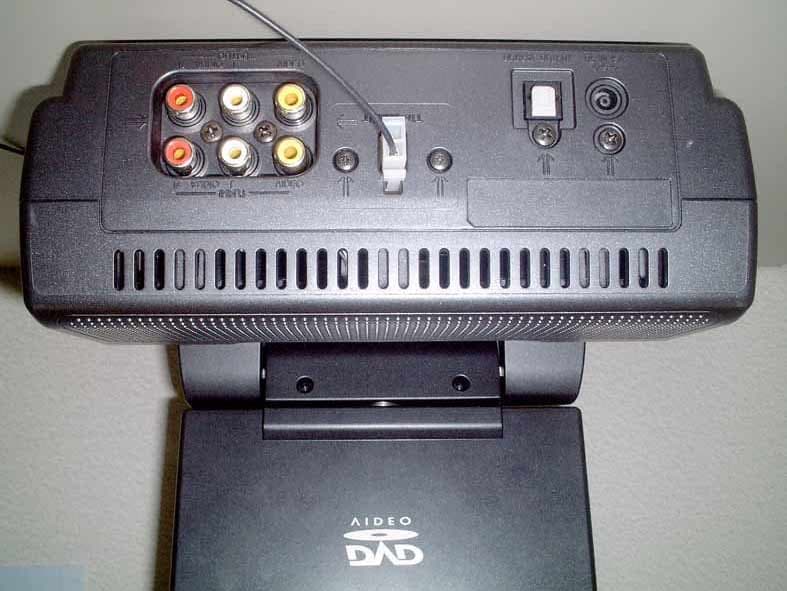
Click to zoom
Application Details
- Equipment Class
- DXX - Part 15 Low Power Communication Device Transmitter
- Date of Grant
- Mar 02, 2004
- Application Purpose
- Original Equipment
- Date of Application
- Mar 02, 2004
- Equipment Note
- DVD Player With FM Transmitter
- Frequency Range
- 88.30000000 - 89.90000000
- Company
- Sony Group Corporation
- Country
- Japan
Documents & Files
Document Text
Text extracted from the exhibit documents filed with the FCC. Open a document above to read the original.
Users Manual
© 2004 Sony Corporation MV-65ST For installation and connections, refer to “Connection” on page 8. Owner’s Record The model and serial numbers are located on the bottom of the unit. Record these numbers in the space provided below. Refer to these numbers whenever you call upon your Sony dealer regarding this product. Model No. MV-65ST Serial No. 2-021-315-11 (1) Operating Instructions Portable DVD Player 2 DANGERINVISIBLE AVOID DIRECT EXPOSURE TO BEAM. LASER RADIATION WHEN OPEN. CAUTION The use of optical instruments with this product will increase eye hazard. CAUTION Use of controls or adjustments or performance of procedures other than those specified herein may result in hazardous radiation exposure. This is located on the drive unit's internal chassis. To prevent fire or shock hazard, do not expose the unit to rain or moisture. This symbol is intended to alert the user to the presence of uninsulated “dangerous voltage” within the product’s enclosure that may be of sufficient magnitude to constitute a risk of electric shock to persons. This symbol is intended to alert the user to the presence of important operating and maintenance (servicing) instructions in the literature accompanying the appliance. Warning Warning This equipment has been tested and found to comply with the limits for a Class B digital device, pursuant to Part 15 of the FCC Rules. These limits are designed to provide reasonable protection against harmful interference in a residential installation. This equipment generates, uses, and can radiate radio frequency energy and, if not installed and used in accordance with the instructions, may cause harmful interference to radio communications. However, there is no guarantee that interference will not occur in a particular installation. If this equipment does cause harmful interference to radio or television reception, which can be determined by turning the equipment off and on, the user is encouraged to try to correct the interference by one or more of the following measures: — Reorient or relocate the receiving antenna. — Increase the separation between the equipment and receiver. — Connect the equipment into an outlet on a circuit different from that to which the receiver is connected. — Consult the dealer or an experienced radio/TV technician for help. You are cautioned that any changes or modifications not expressly approved in this manual could void your authority to operate this equipment. CAUTION The use of optical instruments with this product will increase eye hazard. For the customers in the United States This product contains mercury. Disposal of this product may be regulated if sold in the United States. For disposal or recycling information, please contact your local authorities or the Electronics Industries Alliance (http://www.eiae.org). 3 Table of Contents Welcome ! .............................................................. 4 Precautions ............................................................ 4 About this manual ............................................... 5 About discs this player can play ........................ 6 Connection ............................................................ 8 Resetting the player ........................................... 10 Location of controls ........................................... 11 Various Playback Playing a disc ...................................................... 13 Searching a chapter/title/track directly .......... 14 Resume playback ................................................. 15 Using MP3/JPG menu ........................................ 15 Displaying elapsed time ................................... 16 Changing the subtitle language ....................... 17 Using a DVD menu ............................................ 18 Using the TOP MENU button ............................ 18 Using the MENU button ..................................... 18 Changing the audio language .......................... 19 Changing angles ................................................. 19 Changing the audio output .............................. 20 Using the PBC (playback control) function .... 20 Changing Setup System settings — SYSTEM menu .................. 21 Selecting the language on the menus — OSD LANGUAGE ..................................... 21 Setting the screen saver — SCREEN SAVER ........................................ 22 Returning this player to the factory setting — LOAD SETUP DEF .................................... 22 Settings for DVD playback — DVD SETUP menu .................................. 22 Selecting the audio language for DVD — AUDIO ....................................................... 22 Displaying the subtitles for DVD — SUBTITLE ................................................... 23 Setting the aspect ratio for the TV screen — TV SCREEN ............................................... 23 Displaying the multi-angle notice — ANGLE MARK .......................................... 23 Preparing for the initial parental setting — PARENTAL CONTROL .......................... 23 Setting the password — PASS WORD .............. 24 Selecting the speaker mode — SPEAKER menu ....................................... 25 Selecting the downmix mode — DOWNMIX ................................................ 25 Selecting the digital audio output mode — AUDIO menu ........................................... 25 Selecting the color system for the output video signal — VIDEO menu ..................... 26 Monitoring video signals input from the connected device ........................................... 26 Selecting the color system for the input video signal .................................................... 27 Settings by using the MENU button on the monitor ........................................................... 27 Adjusting the contrast ......................................... 27 Adjusting the brightness ..................................... 28 Adjusting the color ..................................…
Text truncated - open the document above for the full version.
External Photos
Top Left Rear Top – LC D Front Bottom (Label Location) Right
Internal Photos
Internal – 1 Internal – 2 Internal – 3 Internal – 4 Internal – 5 Internal – 6 Internal – 7 Internal – 8 PWB – amp – A PWB – amp – B PWB – key – A PWB – key – B PWB – monitor – A PWB – monitor – B PWB – power – A PWB – power – B
Test Report
JAPAN QUALITY ASSURANCE ORGANIZATION 21-25, KINUTA 1-CHOME, SETAGAYA-KU, TOKYO 157-8573 JAPAN PHONE +81-3-3416-0111, FAX +81-3-3416-9691 JQA APPLICATION NO.: 400-30808 Issue Date : February 19, 2004 Page 1 of 37 EMI TEST REPORT JQA APPLICATION NO. : 400-30808 Model No. : MV-65ST Type of Equipment : DVD Player(incorporated with FM Transmitter) Regulations Applied : CFR 47 FCC Rules and Regulations Part 15 FCC ID : AK8MV65ST Applicant : SONY EMCS Corporation Address : 2-15-3 Konan, Minato-ku, Tokyo 108-6201, Japan Manufacturer : SONY Corporation Address : 6-7-35 Kitashinagawa, Shinagawa-ku, Tokyo 141-0001, Japan Received date of EUT : January 29, 2004 Final Judgment : Passed Test results in this report are obtained in use of equipment that is traceable to National Institute of Advanced Industrial Science and Technology (AIST) of Japan and Communication Research Laboratory (CRL) of Japan. The test results only respond to the tested sample. This report should not be reproduced except in full, without the written approval of JQA EMC Engineering Dept. Testing Div. C O P Y JQA Application No. :400-30808 FCC ID :AK8MV65ST Model No. :MV-65ST Issue Date :February 19, 2004 Standard :CFR 47 FCC Rules Part 15 Page 2 of 37 JAPAN QUALITY ASSURANCE ORGANIZATION TABLE OF CONTENTS Page 1 Documentation 1.1 Test Regulation 3 1.2 General Information 3 1.3 Test Condition 4 – 8 1.4 EUT Modifications / Deviation from Standard 9 1.5 Test results 10 1.6 Summary 11 1.7 Test Configuration / Operation of EUT 12 1.8 EUT Arrangement(Drawing) 13 1.9 Preliminary Test and Test-setup (Drawings) 14 – 19 1.10 EUT Arrangement (Photographs) 20 – 22 2 Test Data 2.1 AC Power Line Conducted Emission 23 – 24 2.2 Radiated Emission (Electric Field) 25 – 30 2.3 Frequency Stability N/A 2.4 Occupied Bandwidth 31 – 33 3 Appendix Test instruments List 34 – 37 C O P Y JQA Application No. :400-30808 FCC ID :AK8MV65ST Model No. :MV-65ST Issue Date :February 19, 2004 Standard :CFR 47 FCC Rules Part 15 Page 3 of 37 JAPAN QUALITY ASSURANCE ORGANIZATION 1 DOCUMENTATION 1.1 TEST REGULATION FCC Rules and Regulations Part 15 Subpart A and C Intentional Radiators Test procedure : AC power line conducted emission, radiated emission, frequency stability and occupied bandwidth tests were performed according to the procedures in ANSI C63.4-2001. 1.2 GENERAL INFORMATION 1.2.1 Test facility : 1) Test Facility located at EMC Engineering Dept. Testing Div. : - No.2 and 3 Anechoic Chambers( 3 meters Site ). - Shielded Enclosure. Expiration date of FCC test facility filing : May 27, 2005 2) EMC Engineering Dept. Testing Div. is recognized under the National Voluntary Laboratory accreditation Program for satisfactory compliance established in title 15, Part 285 Code of Federal Regulations. NVLAP Lab Code : 200189-0 (Effective through : June 30, 2004) 1.2.2 Description of the Equipment Under Test (EUT) : 1) Type of Equipment : DVD Player (Incorporated with FM Transmitter) 2) Product Type : Pre-Production 3) Category : Low Power Transmitter 4) EUT Authorization : Certification 5) FCC ID : AK8MV65ST 6) Trade Name : SONY 7) Model No. : MV-65ST 8) Operating Frequency Range : 88.3 – 89.9 MHz 9) Highest Frequency Used in the EUT : 310 +/- 40 MHz 10) Serial No. : - 11) Date of Manufacture : - 12) Power Rating : DC 12.0V from the AC Adaptor 13) EUT Grounding : None 1.2.3 Definitions for symbols used in this test report : x - indicates that the listed condition, standard or equipment is applicable for this report. - indicates that the listed condition, standard or equipment is not applicable for this report. C O P Y JQA Application No. :400-30808 FCC ID :AK8MV65ST Model No. :MV-65ST Issue Date :February 19, 2004 Standard :CFR 47 FCC Rules Part 15 Page 4 of 37 JAPAN QUALITY ASSURANCE ORGANIZATION 1.3 TEST CONDITION 1.3.1 The measurement of the AC Power Line Conducted Emission x - was performed in the following test site. - was not applicable. Test location : Safety & EMC Center EMC Engineering Dept. Testing Div. 21-25, Kinuta 1-chome, Setagaya-ku, Tokyo 157-8573, Japan x - Shielded Enclosure - Anechoic Chamber No. 2 (portable Type) Used test instruments : Type Number of test instruments (Refer to Appendix) Test Receiver TR01 Spectrum Analyzer SA06 Cable CA03 AMN(for EUT) NE01 AMN(for Peripheral) N/A Termination N/A C O P Y JQA Application No. :400-30808 FCC ID :AK8MV65ST Model No. :MV-65ST Issue Date :February 19, 2004 Standard :CFR 47 FCC Rules Part 15 Page 5 of 37 JAPAN QUALITY ASSURANCE ORGANIZATION 1.3.2 The measurement of the Radiated Emission(9 kHz – 30 MHz) x - was performed in the following test site. - was not applicable. Test location : Safety & EMC Center EMC Engineering Dept. Testing Div. 21-25, Kinuta 1-chome, Setagaya-ku, Tokyo 157-8573, Japan x - Anechoic Chamber No. 2 (3 meters) - Anechoic Chamber No. 3 (3 meters) Validation of Site Attenuation : 1) Last Confirmed Date : N/A 2) Interval : N/A Used test instruments : Type Number of test instruments (Refer to Appendix) Test Receiver TR07 Antenna AN01 Cable CA06 C O P Y JQA Application No. :400-30808 FCC ID :AK8MV65ST Model No. :MV-65ST Issue Date :February 19, 2004 Standard :CFR 47 FCC Rules Part 15 Page 6 of 37 JAPAN QUALITY ASSURANCE ORGANIZATION 1.3.3 The measurement of the Radiated Emission(30 MHz – 1000 MHz) x - was performed in the following test site. - was not applicable. Test location : Safety & EMC Center EMC Engineering Dept. Testing Div. 21-25, Kinuta 1-chome, Setagaya-ku, Tokyo 157-8573, Japan x - Anechoic Chamber No. 2 (3 meters) - Anechoic Chamber No. 3 (3 meters) Validation of Site Attenuation : 1) Last Confirmed Date :March, 2003 2) Interval :1 year Used test instruments : Type Number of test instruments (Refer to Appendix) Test Receiver TR05 Antenna AN06, AN08 Cable CA01 RF Amplifier N/A C O P Y JQA Application No. :400-30808 FCC ID :AK8MV65ST Model No. :MV-65ST Issue Date :February 19, 2004 Standard :CFR 47 FCC Rules Part 15 Page 7 of 37 JAPAN QUALITY ASSURANCE ORGANIZATION 1.3.4 The me…
Text truncated - open the document above for the full version.
Test Setup Photos
JQA Application No. :400-30808 FCC ID :AK8MV65ST Model No. :MV-65ST Issue Date :February 19, 2004 Standard :CFR 47 FCC Rules Part 15 Page 20 of 37 JAPAN QUALITY ASSURANCE ORGANIZATION 1.10 TEST ARRANGEMENT (PHOTOGRAPHS) PHOTOGRAPHS OF EUT CONFIGURATION FOR RADIATED EMISSIONS MEASUREMENT Photograph present configuration with maximum emission C O P Y JQA Application No. :400-30808 FCC ID :AK8MV65ST Model No. :MV-65ST Issue Date :February 19, 2004 Standard :CFR 47 FCC Rules Part 15 Page 21 of 37 JAPAN QUALITY ASSURANCE ORGANIZATION PHOTOGRAPHS OF EUT CONFIGURATION FOR RADIATED EMISSIONS MEASUREMENT Photograph present configuration with maximum emission C O P Y JQA Application No. :400-30808 FCC ID :AK8MV65ST Model No. :MV-65ST Issue Date :February 19, 2004 Standard :CFR 47 FCC Rules Part 15 Page 22 of 37 JAPAN QUALITY ASSURANCE ORGANIZATION PHOTOGRAPHS OF EUT CONFIGURATION FOR AC POWER LINE CONDUCTED EMISSIONS MEASUREMENT Photograph present configuration with maximum emission - Front View – - Side View – C O P Y
Contact Information
Applicant
Kazuyuki Hori(Chief EMC/RF Compliance Specialist)
Test Firm
Japan Quality Assurance Org.Tetsuo Kato
Technical Specifications
| # | Rule Parts | Frequency Range | Power Output |
|---|---|---|---|
| 1 | 15C | 88.3 MHz - 89.9 MHz | - |
Other Applications from Sony Group Corporation
AK8WW81782
Aug 21, 2026Radio Equipment
Equipment Class
DSS - Part 15 Spread Spectrum TransmitterAK8CFIZCP2
Aug 03, 2026Wireless Controller
Equipment Class
DSS - Part 15 Spread Spectrum TransmitterAK8OEV321MUH
Apr 14, 2026LCD Monitor
Equipment Class
JAD - Part 15 Class A Digital DeviceAK8OEV431MUH
Apr 14, 2026LCD Monitor
Equipment Class
JAD - Part 15 Class A Digital DeviceAK8OEV271MUH
Apr 14, 2026LCD Monitor
Equipment Class
JAD - Part 15 Class A Digital Device