AK8NTM90015.249 Sound-Sensor Nursery Monitor
Sony Group Corporation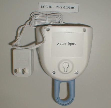
Click to zoom
Application Details
- Equipment Class
- DXX - Part 15 Low Power Communication Device Transmitter
- Date of Grant
- Apr 04, 2002
- Application Purpose
- Original Equipment
- Date of Application
- Apr 04, 2002
- Equipment Note
- 15.249 Sound-Sensor Nursery Monitor
- Frequency Range
- 902.20000000 - 904.30000000
- Company
- Sony Group Corporation
- Country
- Japan
Documents & Files
Document Text
Text extracted from the exhibit documents filed with the FCC. Open a document above to read the original.
Users Manual
3-242-835-11(1) Sony Corporation © 2002 Printed in China Sound-Sensor Nursery Monitor Operating Instructions Manual de instrucciones NTM-910/NTM-900 For customers in the USA Please register this product on line at http://www.sony.com/productregistration. Proper registration will enable us to send you periodic mailings about new products, services, and other important announcements. Registering your product will also allow us to contact you in the unlikely event that the product needs adjustment or modification. Thank you. English WARNING To prevent fire or shock hazard, do not expose the unit to rain or moisture. This symbol is intended to alert the user to the presence of uninsulated “dangerous voltage” within the product’s enclosure that may be of sufficient magnitude to constitute a risk of electric shock to persons. This symbol is intended to alert the user to the presence of important operating and maintenance (servicing) instructions in the literature accompanying the appliance. * The graphical symbols are on the AC power adaptor enclosure on the transmitter. For the customers in the USA You are cautioned that any changes or modifications not expressly approved in this manual could void your authority to operate this equipment. INFORMATION This equipment has been tested and found to comply with the limits for a Class B digital device, pursuant to Part 15 of the FCC Rules. These limits are designed to provide reasonable protection against harmful interference in a residential installation. This equipment generates, uses, and can radiate radio frequency energy and, if not installed and used in accordance with the instructions, may cause harmful interference to radio communications. However, there is no guarantee that interference will not occur in a particular installation. If this equipment does cause harmful interference to radio or television reception, which can be determined by turning the equipment off and on, the user is encouraged to try to correct the interference by one or more of the following measures: – Reorient or relocate the receiving antenna. – Increase the separation between the equipment and receiver. – Connect the equipment into an outlet on a circuit different from that to which the receiver is connected. – Consult the dealer or an experienced radio/TV technician for help. If you have any questions about the product, you may call: Sony Direct Response Center 1-(800)-222-7669 or write to: Sony Direct Response Center 12451 Gateway Blvd. Fort Myers, FL 33913 Declaration of Conformity Trade Name:SONY Model:NTM-910/NTM-900 (Receiver unit) Responsible Party:Sony Electronics Inc. Address:680 Kinderkamack Road, Oradell, NJ 07649 USA Telephone Number: 201-930-6972 This device complies with Part 15 of the FCC Rules. Operation is subject to the following two conditions: (1) This device may not cause harmful interference, and (2) this device must accept any interference received, including interference that may cause undesired operation. For NTM-910 only RECYCLING NICKEL CADMIUM BATTERIES Nickel cadmium batteries are recyclable. You can help preserve our environment by returning your used rechargeable batteries to the collection and recycling location nearest you. Note: In some areas the disposal of nickel cadmium batteries in household or business trash may be prohibited. For more information regarding recycling of rechargeable batteries, call toll free 1-800- 822-8837, or visit http://www.rbrc.org/ Caution: Do not handle damaged or leaking nickel cadmium batteries. Before You Begin Thank you for choosing the Sony Sound-Sensor Nursery Monitor! Before operating the Sound- Sensor Nursery Monitor, please read these instructions thoroughly and retain them for future reference. Features • Up to 27 channels (NTM-910) or 9 channels (NTM-900) for maximized reception. • Voice Activation eliminates most background noise for a more peaceful sleep. • 5 indicators for monitoring sound levels. • RANGE ALM., POWER/BATT and CHARGE (NTM-910) indicators allow you to know the operating condition of the receiver. • Water-resistance allows operating the receiver in slight moisture areas such as kitchen or bathroom. • Operating on rechargeable battery pack (NTM-910). Precautions Safety Precautions • Operate the transmitter only on 120 V AC, 60 Hz; and the receiver on 9 V DC. To operate the receiver on house current, use only the supplied AC power adaptor; do not use any other type. For battery operation, use one rechargeable battery pack BP-T50 (NTM-910) or two size AA (R6) batteries (NTM-900). • Should any solid object or liquid fall into the unit, disconnect the AC power adaptor and remove the battery/batteries, and have the unit checked by a qualified personnel before operating it any further. • If you are not going to use the system for a long time: – Disconnect both transmitter and receiver from the wall outlet by pulling out the plugs of both AC power cord and AC power adaptor respectively. – Remove the battery/batteries out of the receiver to avoid damage from battery leakage. If you have any questions or problems concerning your system, please consult your nearest Sony dealer. Precautions on Usage This product cannot replace responsible adult supervision of a child. It is designed to assist adults in child supervision. Do not use it for medical monitoring of a sick baby or child. • The transmitter detects normal sound levels within a range of 2 to 3 meters (6 to 10 feet) from a child. If the child moves outside of this range, it may not be able to detect sounds from him or her. • It is essential that you check the operating range and condition of the Sound-Sensor Nursery Monitor on initial installation, and on a regular basis after that. • Stay close to the receiver in order to hear normal sounds from it. Check the volume regularly to ensure that it is set high enough. Recharge the rechargeable battery pack (NTM- 910) or replace the batteries (NTM-900) in the receiver or operate it on ho…
Text truncated - open the document above for the full version.
External Photos
FCC ID : AK8NTM900 Model : NTM-900
ID Label/Location Info
FCC ID : AK8NTM900 Model : NTM-900 Certification Information of location with Nameplate Drawing NAMEPLATE Nameplate
Internal Photos
FCC ID : AK8NTM900 Model : NTM-900 FCC ID : AK8NTM900 Model : NTM-900 FCC ID : AK8NTM900 Model : NTM-900
Operational Description
FCC ID : AK8NTM900 Model : NTM-900 CIRCUIT DESCRIPTION of NTM-900 NTM-900 is made up from a pair of components, which are a transmitter(TX) and receiver(RX). So, though FCC application of Certification is only applied for TX of NTM-900, explanation of TX and RX are described on “Circuit Description”. Transmitter(TX) part Configuration : crystal-controlled PLL circuit Transmitting frequency of the TX has 9 channels (please refer to the below). The channel is manually selected by SW302 and SW304. 1ch 902.200MHz 6ch 903.300MHz 2ch 902.300MHz 7ch 904.100MHz 3ch 902.400MHz 8ch 904.200MHz 4ch 903.100MHz 9ch 904.300MHz 5ch 903.200MHz Signal-flow path After IC301 get selected channel signal (which is occurred by SW302 and SW304) through IC302, fundamental frequency is oscillated by Phase Locked Loop circuit (IC301, Q302, D301 and Low Pass Filter). Range of the frequency is 451.1MHz to 452.150MHz. And, second harmonic frequency only of it is amplified by Q301. The frequency(902.2MHz - 904.3MHz) will take a route to FL301(Band Pass Filter), and finally to the Antenna for the transmission. MIC amplifier Voice sound picked up through the MIC will be amplified by Amplifier of IC301, then the sound will be injected to the D301(Variable Capacitor diode) and FM modulation is conducted. Voltage stabilizer circuit Floating voltage will be stabilized on Q305 and D302. FCC ID : AK8NTM900 Model : NTM-900 Receiver(RX) part Configuration : crystal-controlled PLL circuit Receiving frequency of the RX has 9 channels (please refer to the below). The channel is manually selected by SW2 and SW4. That receiving type is Lower Heterodyne with Intermediate Frequency (IF) of 10.7MHz. 1ch 902.200MHz 6ch 903.300MHz 2ch 902.300MHz 7ch 904.100MHz 3ch 902.400MHz 8ch 904.200MHz 4ch 903.100MHz 9ch 904.300MHz 5ch 903.200MHz Signal-flow path A RF-signal received through the antenna will take a route from Q1(RF Amp) to Q2(MIX), FL2 and FL3(Band pass filter), IC1(IF-Amp, Quad detector, Pre-Amp, Expander) and IC6(AF power amp), and finally to speaker. Fundamental frequency(445.750MHz- 446.8MHz) is made by Phase Locked Loop circuit (IC1, Q3, D1 and Low Pass Filter). And, second harmonic frequency(891.5MHz- 893.6MHz) of it will take a route to Q2(MIX). Sound monitor A part of AF signal is branched to Q4(Amp) and the signal is converted to DC voltage. CPU(IC2) reads the DC voltage level and illuminate LEDs(D6-D10). Voice activated system In case AF signal can not be detected for 5 seconds, sound is muted by Q5, Q6, Q7 and Q8 until next AF signal can be detected. Range alarm When AF signal can not be detected (e.g. : reciever is out of area etc.), the device turns the light(D5) on and off, and beep sound is sounded from the speaker. Battery monitor When battery voltage level is down, the device turns the light(D4) on and off, and beep sound is sounded form the speaker. Then the power supply is automatically stopped.
Test Report
Test report No. : 22GE0037-YW-3 Page: 2 of 34 Issued date: March 27, 2002 FCC ID: AK8NTM900 A-pex International Co., Ltd. YOKOWA LAB. 108 Yokowa-cho, Ise-shi, Mie-ken 516-1106 JAPAN Telephone:int +81 596 39 1485 Facsimile: int +81 596 39 0232 CONTENTS PAGE SECTION 1: Client information 3 SECTION 2: Equipment under test (E.U.T.)3 SECTION 3: Test specification, methods & procedures4 SECTION 4: Operation of E.U.T. during testing5 SECTION 5: Summary of test results 6 SECTION 6: Conducted emission 7 SECTION 7: Radiated emission8 APPENDIX 1: Photographs of test setup9 APPENDIX 2: Test instruments9 APPENDIX 3: Data of EMI test9 Test report No. : 22GE0037-YW-3 Page: 3 of 34 Issued date: March 27, 2002 FCC ID: AK8NTM900 A-pex International Co., Ltd. YOKOWA LAB. 108 Yokowa-cho, Ise-shi, Mie-ken 516-1106 JAPAN Telephone:int +81 596 39 1485 Facsimile: int +81 596 39 0232 SECTION 1: Client information Company name: Sony Corporation Address: Sinagawa INTERCITY C Tower 2-15-3 konan Minato-ku, Tokyo, 108-6201, Japan Telephone Number: +81-3-5769-5640 Facsimile Number: +81-3-5769-5962 Contact Person: Kikuo Murata SECTION 2: Equipment under test (E.U.T.) 2.1Identification of E.U.T. Type of Equipment: Nursery Monitor (Transmitter) Model No.: NTM-900 Serial No.: 19 Condition of EUT: Engineering prototype Rating: DC 9V (AC Adaptor: AC120V / 60Hz) Country of Manufacture : Japan Receipt Date of Sample: February 7, 2002 2.2Product Description NTM-900 (referred to as the EUT in this report) is a Nursery Monitor (Transmitter). The specification is as follows; Antenna Type: Wire Antenna Tx Frequency: 902.2MHz, 902.3MHz, 902.4MHz, 903.1MHz, 903.2MHz, 903.3MHz, 904.1MHz, 904.2MHz, 904.3MHz Modulation: F3E Number of Channels: 9 channels Microcomputer Clock: 4MHz Test report No. : 22GE0037-YW-3 Page: 4 of 34 Issued date: March 27, 2002 FCC ID: AK8NTM900 A-pex International Co., Ltd. YOKOWA LAB. 108 Yokowa-cho, Ise-shi, Mie-ken 516-1106 JAPAN Telephone:int +81 596 39 1485 Facsimile: int +81 596 39 0232 SECTION 3: Test specification, methods & procedures 3. 1Test Specification Test Specification: FCC Part 15 Subpart C Section 15.207 and Section 15.249 Title: FCC 47CFR Part15 Radio Frequency Device Subpart C Intentional Radiators Section 15.207 Conducted emission limits; general requirements Section 15.249 Operation in the band 902-928MHz, 2400-2483.5MHz, 5725-5875MHz and 24.0-24.25GHz 3.2Methods & Procedures No.ItemTest ProcedureSpecificationRemarks 1Conducted emissionANSI C63.4:1992Section 15.207(a)- 2Radiated emissionANSI C63.4:1992Section 15.2493m 3.3 Additions or deviations to standards No addition, deviation or exclusion has been made from standards. Test report No. : 22GE0037-YW-3 Page: 5 of 34 Issued date: March 27, 2002 FCC ID: AK8NTM900 A-pex International Co., Ltd. YOKOWA LAB. 108 Yokowa-cho, Ise-shi, Mie-ken 516-1106 JAPAN Telephone:int +81 596 39 1485 Facsimile: int +81 596 39 0232 SECTION 4: Operation of E.U.T. during testing 4.1Operating Modes The EUT exercise program used during radiated and conducted testing was designed to exercise the various system components in a manner similar to typical use. The operating mode/system were as follows: Operation: Transmitting (1kHz Audio Signal Input) CH1: 902.20MHz (Low) CH14: 903.20MHz (Mid) CH27: 904.30MHz (High) Justification: The system was configured in typical fashion (as a customer would normally use it) for testing. 4.2 Configuration and peripherals Front View A:EUT B 1 AC120V/60Hz Top View A:EUT B 1 AC120V/60Hz *Cabling was taken into consideration and test data was taken under worse case conditions. Description of EUT and Support equipment No.ItemModel numberSerial numberManufacturerFCC ID A Nursery Monitor (Transmitter) NTM-90019Sony CorporationAK8NTM900 (EUT) B AC Adaptor--Sony Corporation- List of cables used No.NameLength (m)ShieldBackshell MaterialRemark 1 DC Power Cable1.8N Polyvinyl chloride - Test report No. : 22GE0037-YW-3 Page: 6 of 34 Issued date: March 27, 2002 FCC ID: AK8NTM900 A-pex International Co., Ltd. YOKOWA LAB. 108 Yokowa-cho, Ise-shi, Mie-ken 516-1106 JAPAN Telephone:int +81 596 39 1485 Facsimile: int +81 596 39 0232 SECTION 5: Summary of test results 5.1Test results No.ItemTest ProcedureSpecificatio n Worst marginResult 1 Conducted emission ANSI C63.4:1992Section 15.207(a) 30.2dB (20.0000MHz:L1): CH21Complied 2 Radiated emissionANSI C63.4:1992Section 15.249 Fundamental 4.9dB (902.20MHz: Vertical) : CH1 6.3dB (903.20MHz: Vertical) : CH11 6.5dB (904.30MHz: Vertical) : CH21 Spurious 6.8dB (2255.52MHz: Horizontal,AV) : CH1 6.5dB (451.60MHz: Horizontal) : CH11 6.7dB (452.15MHz: Hrizontal) : CH21 Complied A-PEX INTERNATIONAL hereby confirms that E.U.T., in the configuration tested, complies with the specifications FCC Part 15 Subpart C. <–20dB Bandwidth> Refer to Appendix 3. 5.2Uncertainty Conducted Emission Test The measurement uncertainty (with a 95% confidence level) for this test was ±2.0dB. The data listed in this test report has enough margin, more than site margin. Radiated Emission Test The measurement uncertainty (with a 95% confidence level) for this test using Biconical antenna is ±4.4dB. The measurement uncertainty (with a 95% confidence level) for this test using Logperiodic antenna is ±4.8dB. The measurement uncertainty (with a 95% confidence level) for this test using Horn antenna is ±5.8dB. The data listed in this test report has enough margin, more than site margin. 5.3Test Location A-PEX International Co.,Ltd. Yokowa No.3 test site 108 Yokowa-cho, Ise-shi, Mie-ken 516-1106 Japan Telephone number: +81-596-39-1485 Facsimile number: +81-596-39-0232 This site has been fully described in a report submitted to FCC office, and listed on September 12, 2000 (Registration number: 90412). *NVLAP Lab. code : 200109-0 5.4Photographs of test setup Refer to Appendix 1. 5.5Test instruments Refer to Appendix 2. 5.6Data of EMI Test Refer to Appendix 3. Test report No. : 22GE0037-YW-3 Page: 7 of 34 Issued date: March 27, 2002 FCC ID: AK8NTM9…
Text truncated - open the document above for the full version.
Test Setup Photos
Test report No. : 22GE0037-YW-3 Page: 10 of 34 Issued date: March 27, 2002 FCC ID: AK8NTM900 A-pex International Co., Ltd. YOKOWA LAB. 108 Yokowa-cho, Ise-shi, Mie-ken 516-1106 JAPAN Telephone:int +81 596 39 1485 Facsimile: int +81 596 39 0232 Conducted emission Test report No. : 22GE0037-YW-3 Page: 11 of 34 Issued date: March 27, 2002 FCC ID: AK8NTM900 A-pex International Co., Ltd. YOKOWA LAB. 108 Yokowa-cho, Ise-shi, Mie-ken 516-1106 JAPAN Telephone:int +81 596 39 1485 Facsimile: int +81 596 39 0232 Radiated emission
Contact Information
Applicant
Kazuyuki Hori(Chief EMC/RF Compliance Specialist)
Technical Contact
A-Pex International Co., LtdNaoki Sakamoto
[email protected]81-596-39-1485
108 Yokowa-cho · Ise-shi, Mie-ken · Japan
Non-Technical Contact
A-Pex International Co., LtdKanako Sanda
[email protected]81-596-24-8116
Test Firm
UL Japan, IncMitsuru Fujimura
Technical Specifications
| # | Rule Parts | Frequency Range | Power Output |
|---|---|---|---|
| 1 | 15C | 902.2 MHz - 904.3 MHz | - |
Other Applications from Sony Group Corporation
AK8WW81782
Aug 21, 2026Radio Equipment
Equipment Class
DSS - Part 15 Spread Spectrum TransmitterAK8CFIZCP2
Aug 03, 2026Wireless Controller
Equipment Class
DSS - Part 15 Spread Spectrum TransmitterAK8OEV321MUH
Apr 14, 2026LCD Monitor
Equipment Class
JAD - Part 15 Class A Digital DeviceAK8OEV431MUH
Apr 14, 2026LCD Monitor
Equipment Class
JAD - Part 15 Class A Digital DeviceAK8OEV271MUH
Apr 14, 2026LCD Monitor
Equipment Class
JAD - Part 15 Class A Digital Device