AK8NTM91015.249 Sound-Sensor Nursery Monitor
Sony Group Corporation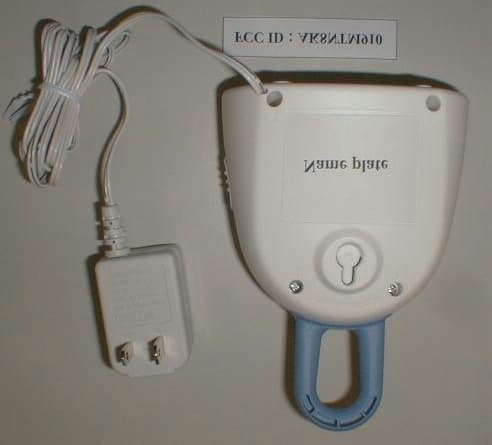
Click to zoom
Application Details
- Equipment Class
- DXX - Part 15 Low Power Communication Device Transmitter
- Date of Grant
- Apr 04, 2002
- Application Purpose
- Original Equipment
- Date of Application
- Apr 04, 2002
- Equipment Note
- 15.249 Sound-Sensor Nursery Monitor
- Frequency Range
- 902.20000000 - 904.90000000
- Company
- Sony Group Corporation
- Country
- Japan
Documents & Files
Document Text
Text extracted from the exhibit documents filed with the FCC. Open a document above to read the original.
External Photos
FCC ID : AK8NTM910 Model : NTM-910
ID Label/Location Info
FCC ID : AK8NTM910 Model : NTM-910 Certification Information of location with Nameplate Drawing NAMEPLATE Nameplate
Internal Photos
FCC ID : AK8NTM910 Model : NTM-910 FCC ID : AK8NTM910 Model : NTM-910 FCC ID : AK8NTM910 Model : NTM-910
Operational Description
FCC ID : AK8NTM910 Model : NTM-910 CIRCUIT DESCRIPTION of NTM-910 NTM-910 is made up from a pair of components, which are a transmitter(TX) and receiver(RX). So, though FCC application of Certification is only applied for TX of NTM-910, explanation of TX and RX are described on “Circuit Description”. Transmitter(TX) part Configuration : crystal-controlled PLL circuit Transmitting frequency of the TX has 27 channels (please refer to the below). The channel is manually selected by SW302 , SW303 and SW304. 1ch 902.200MHz10ch 903.100MHz19ch 904.100MHz 2ch 902.300MHz11ch 903.200MHz20ch 904.200MHz 3ch 902.400MHz12ch 903.300MHz21ch 904.300MHz 4ch 902.500MHz13ch 903.400MHz22ch 904.400MHz 5ch 902.600MHz14ch 903.500MHz23ch 904.500MHz 6ch 902.700MHz15ch 903.700MHz24ch 904.600MHz 7ch 902.800MHz16ch 903.800MHz25ch 904.700MHz 8ch 902.900MHz17ch 903.900MHz26ch 904.800MHz 9ch 903.000MHz18ch 904.000MHz27ch 904.900MHz Signal-flow path After IC301 get selected channel signal (which is occurred by SW302, SW303 and SW304) through IC302, fundamental frequency is oscillated by Phase Locked Loop circuit (IC301, Q302, D301 and Low Pass Filter). Range of the frequency is 451.1MHz to 452.450MHz. And, second harmonic frequency only of it is amplified by Q301. The frequency(902.2MHz - 904.9MHz) will take a route to FL301(Band Pass Filter), and finally to the Antenna for the transmission. MIC amplifier Voice sound picked up through the MIC will be amplified by Amplifier of IC301, then the sound will be injected to the D301(Variable Capacitor diode) and FM modulation is conducted. Voltage stabilizer circuit Floating voltage will be stabilized on Q305 and D302. FCC ID : AK8NTM910 Model : NTM-910 Receiver(RX) part Configuration : crystal-controlled PLL circuit Receiving frequency of the RX has 27 channels (please refer to the below). The channel is manually selected by SW2, SW3 and SW4. That receiving type is Lower Heterodyne with Intermediate Frequency (IF) of 10.7MHz. 1ch 902.200MHz10ch 903.100MHz19ch 904.100MHz 2ch 902.300MHz11ch 903.200MHz20ch 904.200MHz 3ch 902.400MHz12ch 903.300MHz21ch 904.300MHz 4ch 902.500MHz13ch 903.400MHz22ch 904.400MHz 5ch 902.600MHz14ch 903.500MHz23ch 904.500MHz 6ch 902.700MHz15ch 903.700MHz24ch 904.600MHz 7ch 902.800MHz16ch 903.800MHz25ch 904.700MHz 8ch 902.900MHz17ch 903.900MHz26ch 904.800MHz 9ch 903.000MHz18ch 904.000MHz27ch 904.900MHz Signal-flow path A RF-signal received through the antenna will take a route from Q1(RF Amp) to Q2(MIX), FL2 and FL3(Band pass filter), IC1(IF-Amp, Quad detector, Pre-Amp, Expander) and IC6(AF power amp), and finally to speaker. Fundamental frequency(445.750MHz - 447.100MHz) is made by Phase Locked Loop circuit (IC1, Q3, D1 and Low Pass Filter). And, second harmonic frequency(891.5MHz- 894.2MHz) of it will take a route to Q2(MIX). Sound monitor A part of AF signal is branched to Q4(Amp) and the signal is converted to DC voltage. CPU(IC2) reads the DC voltage level and illuminate LEDs(D6 - D10). Voice activated system In case AF signal can not be detected for 5 seconds, sound is muted by Q5, Q6, Q7 and Q8 until next AF signal can be detected. FCC ID : AK8NTM910 Model : NTM-910 Receiver(RX) part Range alarm When AF signal can not be detected (e.g. : reciever is out of area etc.), the device turns the light(D5) on and off, and beep sound is sounded from the speaker. Battery monitor When battery voltage level is down, the device turns the light(D4) on and off, and beep sound is sounded form the speaker. Then the power supply is automatically stopped.
Test Report
Test report No. : 22GE0037-YW-1 Page: 2 of 34 Issued date: March 27, 2002 FCC ID: AK8NTM910 A-pex International Co., Ltd. YOKOWA LAB. 108 Yokowa-cho, Ise-shi, Mie-ken 516-1106 JAPAN Telephone:int +81 596 39 1485 Facsimile: int +81 596 39 0232 CONTENTS PAGE SECTION 1: Client information 3 SECTION 2: Equipment under test (E.U.T.)3 SECTION 3: Test specification, methods & procedures4 SECTION 4: Operation of E.U.T. during testing5 SECTION 5: Summary of test results 6 SECTION 6: Conducted emission 7 SECTION 7: Radiated emission8 APPENDIX 1: Photographs of test setup9 APPENDIX 2: Test instruments9 APPENDIX 3: Data of EMI test9 Test report No. : 22GE0037-YW-1 Page: 3 of 34 Issued date: March 27, 2002 FCC ID: AK8NTM910 A-pex International Co., Ltd. YOKOWA LAB. 108 Yokowa-cho, Ise-shi, Mie-ken 516-1106 JAPAN Telephone:int +81 596 39 1485 Facsimile: int +81 596 39 0232 SECTION 1: Client information Company name: Sony Corporation Address: Sinagawa INTERCITY C Tower 2-15-3 konan Minato-ku, Tokyo, 108-6201, Japan Telephone Number: +81-3-5769-5640 Facsimile Number: +81-3-5769-5962 Contact Person: Kikuo Murata SECTION 2: Equipment under test (E.U.T.) 2.1Identification of E.U.T. Type of Equipment: Nursery Monitor (Transmitter) Model No.: NTM-910 Serial No.: 20 Condition of EUT: Engineering prototype Rating: DC 9V (AC Adaptor: AC120V / 60Hz) Country of Manufacture : Japan Receipt Date of Sample: February 7, 2002 2.2Product Description NTM-910 (referred to as the EUT in this report) is a Nursery Monitor (Transmitter). The specification is as follows; Antenna Type: Wire Antenna Tx Frequency: 902.2MHz to 904.9MHz (100kHz step) Modulation: F3E Number of Channels: 27 channels Microcomputer Clock: 4MHz Test report No. : 22GE0037-YW-1 Page: 4 of 34 Issued date: March 27, 2002 FCC ID: AK8NTM910 A-pex International Co., Ltd. YOKOWA LAB. 108 Yokowa-cho, Ise-shi, Mie-ken 516-1106 JAPAN Telephone:int +81 596 39 1485 Facsimile: int +81 596 39 0232 SECTION 3: Test specification, methods & procedures 3. 1Test Specification Test Specification: FCC Part 15 Subpart C Section 15.207 and Section 15.249 Title: FCC 47CFR Part15 Radio Frequency Device Subpart C Intentional Radiators Section 15.207 Conducted emission limits; general requirements Section 15.249 Operation in the band 902-928MHz, 2400-2483.5MHz, 5725-5875MHz and 24.0-24.25GHz 3.2Methods & Procedures No.ItemTest ProcedureSpecificationRemarks 1Conducted emissionANSI C63.4:1992Section 15.207(a)- 2Radiated emissionANSI C63.4:1992Section 15.2493m 3.3 Additions or deviations to standards No addition, deviation or exclusion has been made from standards. Test report No. : 22GE0037-YW-1 Page: 5 of 34 Issued date: March 27, 2002 FCC ID: AK8NTM910 A-pex International Co., Ltd. YOKOWA LAB. 108 Yokowa-cho, Ise-shi, Mie-ken 516-1106 JAPAN Telephone:int +81 596 39 1485 Facsimile: int +81 596 39 0232 SECTION 4: Operation of E.U.T. during testing 4.1Operating Modes The EUT exercise program used during radiated and conducted testing was designed to exercise the various system components in a manner similar to typical use. The operating mode/system were as follows: Operation: Transmitting (1kHz Audio Signal Input) CH1: 902.20MHz (Low) CH14: 903.50MHz (Mid) CH27: 904.90MHz (High) Justification: The system was configured in typical fashion (as a customer would normally use it) for testing. 4.2 Configuration and peripherals Front View A:EUT B 1 AC120V/60Hz Top View A:EUT B 1 AC120V/60Hz *Cabling was taken into consideration and test data was taken under worse case conditions. Description of EUT and Support equipment No.ItemModel numberSerial numberManufacturerFCC ID A Nursery Monitor (Transmitter) NTM-91020Sony CorporationAK8NTM910 (EUT) B AC Adaptor--Sony Corporation- List of cables used No.NameLength (m)ShieldBackshell MaterialRemark 1 DC Power Cable1.8N Polyvinyl chloride - Test report No. : 22GE0037-YW-1 Page: 6 of 34 Issued date: March 27, 2002 FCC ID: AK8NTM910 A-pex International Co., Ltd. YOKOWA LAB. 108 Yokowa-cho, Ise-shi, Mie-ken 516-1106 JAPAN Telephone:int +81 596 39 1485 Facsimile: int +81 596 39 0232 SECTION 5: Summary of test results 5.1Test results No.ItemTest ProcedureSpecificatio n Worst marginResult 1Conducted emission ANSI C63.4:1992Section 15.207(a) 18.9dB (20.0001MHz:L1): CH27Complied 2Radiated emissionANSI C63.4:1992Section 15.249 Fundamental 5.7dB (902.20MHz: Vertical) : CH1 8.3dB (903.48MHz: Vertical) : CH14 8.3dB (904.93MHz: Vertical) : CH27 Spurious 6.2dB (46.02MHz: Vertical) : CH1 8.2dB (2258.82MHz: Vertical,AV) : CH14 7.4dB (2262.38MHz: Horizontal,AV) : CH27 Complied A-PEX INTERNATIONAL hereby confirms that E.U.T., in the configuration tested, complies with the specifications FCC Part 15 Subpart C. <–20dB Bandwidth> Refer to Appendix 3. 5.2Uncertainty Conducted Emission Test The measurement uncertainty (with a 95% confidence level) for this test was ±2.0dB. The data listed in this test report has enough margin, more than site margin. Radiated Emission Test The measurement uncertainty (with a 95% confidence level) for this test using Biconical antenna is ±4.4dB. The measurement uncertainty (with a 95% confidence level) for this test using Logperiodic antenna is ±4.8dB. The measurement uncertainty (with a 95% confidence level) for this test using Horn antenna is ±5.8dB. The data listed in this test report has enough margin, more than site margin. 5.3Test Location A-PEX International Co.,Ltd. Yokowa No.2 and No.3 test site 108 Yokowa-cho, Ise-shi, Mie-ken 516-1106 Japan Telephone number: +81-596-39-1485 Facsimile number: +81-596-39-0232 No.2 test site has been fully described in a report submitted to FCC office, and listed on October 26, 2000 (Registration number: 90411). No.3 test site has been fully described in a report submitted to FCC office, and listed on September 12, 2000 (Registration number: 90412). *NVLAP Lab. code : 200109-0 5.4Photographs of test setup Refer to Appendix 1. 5.5Test instruments Refer to Appendix 2. 5.6Data of EMI Test Refer to Appe…
Text truncated - open the document above for the full version.
Contact Information
Applicant
Kazuyuki Hori(Chief EMC/RF Compliance Specialist)
Technical Contact
A-Pex International Co., Ltd.Naoki Sakamota
[email protected]81-596-39-1485
108 Yokowa-cho · Ise-shi, Mie-ken · Japan
Non-Technical Contact
A-Pex International Co., Ltd.Kanako Sanda
[email protected]81-596-24-8116
Test Firm
UL Japan, IncMitsuru Fujimura
Technical Specifications
| # | Rule Parts | Frequency Range | Power Output |
|---|---|---|---|
| 1 | 15C | 902.2 MHz - 904.9 MHz | - |
Other Applications from Sony Group Corporation
AK8WW81782
Aug 21, 2026Radio Equipment
Equipment Class
DSS - Part 15 Spread Spectrum TransmitterAK8CFIZCP2
Aug 03, 2026Wireless Controller
Equipment Class
DSS - Part 15 Spread Spectrum TransmitterAK8OEV321MUH
Apr 14, 2026LCD Monitor
Equipment Class
JAD - Part 15 Class A Digital DeviceAK8OEV431MUH
Apr 14, 2026LCD Monitor
Equipment Class
JAD - Part 15 Class A Digital DeviceAK8OEV271MUH
Apr 14, 2026LCD Monitor
Equipment Class
JAD - Part 15 Class A Digital Device